 |
 |
 |
| Главная Журналы Популярное Audi - почему их так назвали? Как появилась марка Bmw? Откуда появился Lexus? Достижения и устремления Mercedes-Benz Первые модели Chevrolet Электромобиль Nissan Leaf |
Главная » Журналы » Transformer elementary form 1 ... 8 9 10 11 12 13 14 ... 38 reluctance of the iron can be neglected in comparison with that of the air gap. For a square stack of punchings, the increase of inductance due to fringing is = 1 + log. (39) Equation 39 is plotted in Fig. 72 with core shape УA/S as abscissas and gap ratio Ig/S as parameter.
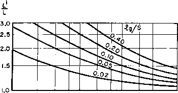 0.2 0.3 0.4 Fig. 72. Increase of reactor inductance with flux fringing at core gap. If the air gap is enclosed by a coil, as at the top of Fig. 72, flux fringing is reduced because of the magnetizing force set up near the gap by the ampere-turns of the coil. A coil fitting tightly all around the core would produce no fringing at all. As the distance from inside of the coil to the core increases, so does the fringing. Fringing therefore depends upon the coil form thickness; if it materially exceeds the air gap per leg, fringing is nearly the same as it would be in a core gap which is not enclosed by a coil. Figure 72 is based on a thick coil form. 42. Similitude in Design. Charts such as Fig. 63 show that ratings are related to size in an orderly sequence, provided that certain proportions between core dimensions are maintained. Figure 63 is for 60 1 See G. Г. Partridge, Phil. Mag., 22 (7th series), 675 (July-December, 1936). cycles. If a transformer is desired for another frequency, its size may be estimated from Table VIII, provided that the same core proportions apply, and similar values of induction and temperature rise are used. If the new conditions are widely different, due allowance must be made for them or the estimate will not be accurate. Table VIII and Figs. 63 and 71 are examples of similitude. If all variations between ratings are taken into account, similitude provides a very accurate basis for estimating new sizes; for the transformer designer there is no better basis for starting a new design. 43. Reactor Current Interruption. Sudden interruption of current through a reactor may cause high voltages to develop in the winding. This may be seen by considering the voltage across a reactor with linear inductance L and varying current i in the winding. Let current i be substituted for Im in equation 37; it may be transposed to give Ф = lOLi/N (37a) where L is in henrys and г in amperes. If this expression for ф be substituted in equation 1, we obtain e = -L- (40) Equation 40 states that the magnitude of voltage across a reactor is equal to the inductance multiplied by the rate of current change with time. The sense or direction of this voltage is always such as to oppose the current change. Therefore, if current interruption takes place instantaneously, inductive voltage is infinitely large. In an actual reactor, losses and capacitance are always present; hence interruption of reactor current forces the reactor voltage to discharge into its own capacitance and loss resistance. The curves of Fig. 73 show how the reactor voltage e rises when steady current / flowing in the reactor is suddenly interrupted. The maximum value to which voltage e could rise under any condition is IR2, where Й2 is the equivalent loss resistance. R2 depends mostly on the reactor iron loss at the resonance frequency determined by reactor inductance L and capacitance C. This frequency is l/T, where T is 1ж-\/ЬС Conditions for high voltage across the reactor occur with high values of /с, the ratio of л/Ь/С to 2R2. If subject to sudden current interruptions, reactors must be insulated to withstand this voltage, or must be protected by spark gaps or other means. The curves of Fig. 73 are based on equation 41: 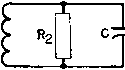 e = VOLTAGE ACROSS REACTOR 1= INITIAL CURRENT THROUGH REACTOR R2=REACT0R LOSS EQUIVALENT RESISTANCE C= REACTOR DISTRIBUTED CAPACITANCE L= REACTOR INDUCTANCE T=2TTVlC 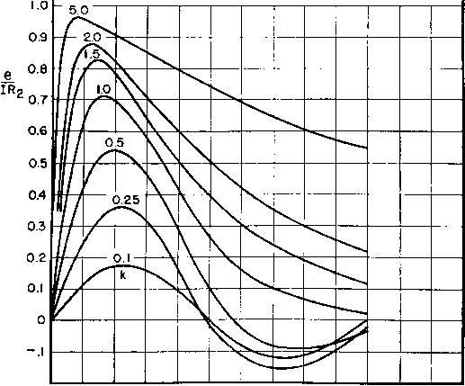 where 0.2 0,4 0.6 0.8 1.0 TIME EXPRESSED AS A FRACTION OF TIME CONSTANT T Fig. 73. Reactor voltage rise. e к Vk - 1 -2ж (41) nil, Ш2 = ~- (fc ± Vfc - 1 ) If there is appreciable circuit or wiring capacitance shunting the reactor after it is disconnected, this contributes to the total reactor capaci-tan e С 44. Transformers with D-C Flux. When there is a net d-c flux in the core, as in single-phase half-wave anode transformers, the choice of core depends on the same principles as in reactors with large a-c flux. The windings carry non-sinusoidal load current, the form of which depends on the circuit. Winding currents may be calculated with the aid of Table I (p. 16). Generally the heating effects of these currents are large. Maximum flux density should be limited as described in Section 39. This precaution is essential in limited power supplies like aircraft or portable generators, lest the generator voltage wave form be badly distorted. On large power systems the rectifier is a minor part of the total load and has no influence on voltage wave form. The chief limitation then is primary winding current, and maximum induction may exceed the usual limits. In single-phase half-wave transformers, air gaps are sometimes provided in the cores to reduce the core flux asymmetry described in Section 12. Transformers designed in this manner resemble reactors in that core induction is calculated as in Sections 37 to 41, depending on the operating conditions. Even in transformers with no air gap, there is a certain amount of incidental reluctance at the joints in both stacked laminations and type С cores. This small gap reduces the degree of core saturation that would exist in half-wave transformers with unbroken magnetic paths. 45. Power Transformer Tests. A power transformer is tested to discover whether the transformer will perform as required, or whether it will give reliable service life. Some tests perform both functions. (a) D-C Resistance. This test is usually made on transformers at the factory as a check on the correctness of wire size in each winding. Variations are caused by wire tolerances, and by difference in winding tension between two lots of coils or between two coil machine operators. About 10 per cent variation can be expected in the d-c resistance of most coils, but this value increases to 20 per cent rather suddenly in sizes smaller than No. 40. The test is made by means of a resistance bridge or specially calibrated meter. (b) Turns Ratio. Once the correct number of turns in each winding is established, correct output voltage can be assured for a coil of given design by measuring the turns. A simple way of doing this is by use of the turns-ratio bridge in Fig. 74. If the turns are correct, the null indicated by the meter occurs at a ratio of resistances R1/R2 = N,/N2 (42) If there is an error in the number of turns of one winding, the null occurs at the wrong value R1/R2. A source of 1,000 cycles is preferable to one of 60 cycles for this test. The smaller current drawn by the transformer reduces IR and IX errors. Harmonics in the source obscure the null, and so the source should be filtered. The null is often made sharper by switching a small variable resistor in series with Ri or R2 to offset any lack of proportion in resistances of windings iVi or N2. 1,000 CYCLE SOURCE 10,000 n , I , , 10,000 g  Fig. 74. Turns-ratio bridge. An accuracy of 0.1 per cent can usually be attained with four-decade resistances. Polarity of winding is also checked by this test, because the bridge will not balance if one winding is reversed. (c) Open-Circuit Inductance {OCL). There are several ways of measuring inductance. If the Q (or ratio of coil reactance to a-c resistance) is high, the check may be made by measuring the current drawn by an appropriate winding connected across a source of known voltage and frequency. This method is limited to those cases where the amount of current drawn can be measured. A more general method makes use of an inductance bridge, of which one form is shown in Fig. 75. If direct current normally flows in the winding, it can be applied through a large choke as shown. Inductance is then measured under the conditions of use. Source voltage should be adjustable for the same reason and should be filtered to produce a sharp null. Rc is provided to compensate for coil a-c resistance. Without it an accurate measurement is rarely attained. Enough data are provided by the test to calculate a-c resistance as well as inductance. When Q is low, as it is in coils with high resistance, better accuracy is obtained with the Maxwell bridge, which is like the Hay bridge except that Xo and Ro are paralleled. Then the equations for bridge balance become Lx = R1R2C Rx = R1R2/RC (43) The Maxwell bridge has the further advantage that the null is independent of the source frequency. 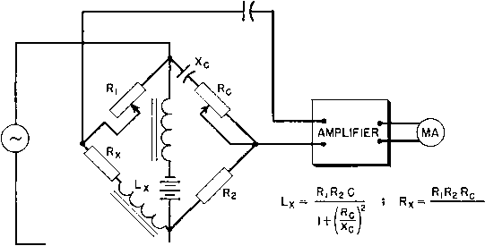 Fig. 75. Modified Hay bridge for measuring inductance. (d) Temperature Rise. Tests to determine whether a transformer overheats are made by measuring the winding resistances before and after a heat run, during which the transformer is loaded up to its rating. Where several secondaries are involved, each should deliver rated voltage and current. Power is applied long enough to allow the transformer temperature to become stable; this is indicated by thermometer readings of core or case temperature taken every half hour until successive readings are the same. Ambient temperature at a nearby location should also be measured throughout the test. The average increase in winding resistance furnishes an indication of the average winding temperature. Figure 76 furnishes a convenient means for finding this temperature. (e) Regulation. It is possible to measure voltage regulation by connecting a voltmeter across the output winding and reading the voltage with load off and on. This method is not accurate because the regulation is usually the difference between two relatively large quantities. Better accuracy can be obtained by multiplying the rated winding currents by the measured winding resistances and using equation 13. If the winding reactance drop is small this equation works well for resistive loads. To measure winding reactance drop, a short-circuit test is used. With the secondary short-circuited, sufficient voltage is applied to the primary to cause rated primary current to о о ю 1.2 ш о 1.0 (О 0.9 -60 -40 -го о 20 40 60 80 100 120 140 160 180 200 temperature с Fig. 76. Copper resistance versus temperature in terms of resistance at 25°C. flow. The quotient E/1 is the vector sum of winding resistances and reactances. Reactance is found from (44) where R includes the resistance of both windings and the meter. Sometimes it is more convenient to measure the leakage inductance wth secondary short-circuited on a bridge and multiply by 27г/. (/} Output Voltage. Although the method described under (e) above is accurate for two-winding transformers, it is not applicable to multi-secondary transformers unless they are tested first with newly calibrated meters to see that all windings deliver proper voltage at full load. Once this is established, values of winding resistance and reactance thereafter can be checked to control the voltage. The interde- pendence of secondary voltages when there is a common primary winding makes such an initial test desirable. This is particularly true in combined filament and plate transformers, for which the best test is the actual rectifier circuit. ig) Losses. Often it is possible to reduce the number of time-consuming heat runs by measuring losses. The copper loss is readily calculated by multiplying the measured values of winding resistance (corrected for operating temperature) by the squares of the respective rated currents. Core loss is measured with open secondary by means of a low-reading wattmeter at rated voltage in the primary circuit. If these losses correspond to the allowable temperature rise, the transformer is safely rated. (h) Insulation. There is no test to which a transformer is subjected which has such a shaky theoretical basis as the insulation test. Yet it is the one test it must pass to be any good. Large quantities of transformers can be built with little or no insulation trouble, but the empirical nature of standard test voltages does not assure insulation adequacy. It has been found over a period of years that, if insulation withstands the standard rule of twice normal voltage plus 1,000 volts rms at 60 cycles for 1 minute, reasonable insulation life is usually obtained. It is possible for a transformer to be extremely under-insulated and still pass this test (see p. 44); conversely, there are conditions under which the rule would be a handicap. Therefore it can only be considered as a rough guide. The manner of making insulation tests depends upon the transformer. Low-voltage windings categorically can be tested by short-circuiting the terminals and applying the test Aoltage from each winding to core or case with other windings grounded. Filament transformers with secondaries insulated for high voltage may be tested in similar manner. But a high-voltage plate transformer with grounded center tap requires unnecessary insulation if it is tested by this method. Instead, a nominal voltage of, say, 1,500 volts is applied between the whole winding and ground; after that the center tap is grounded and a voltage is applied across the primary of such value as to test the end terminals at twice normal plus 1,000 volts. Similar test values can be calculated for windings operating at d-c voltages other than zero. Such a test is called an induced voltage test. It is performed at higher than normal frequency to avoid saturation. An advantage of induced voltage testing is that it tests the layer insulation. If insulation tests are repeated one or more times they may destroy the insulation, because insulation breakdown values decrease with time. Successive applications of test voltage are usually made at either decreased voltage or decreased time. In view of their dubious value, repeated insulation tests are best omitted. Corona tests are not open to this objection. A voltage 5 per cent higher than normal is applied to the winding, and the leads are run through blocking capacitors to the input of a sensitive radio receiver as in Fig. 38. RETMA standard noise values for this test are based primarily on radio reception, but they do indicate whether standard insulation practice is followed. See Table X, Table X. Cobona Voltage RMS Working Voltage Corona Level (kilovolts) (microvolts) Up to 8.6 1,000 8.61 to 15 2,500 Transformers which are subjected to voltage surges may be given impulse tests to determine whether the insulation will withstand the surges. Power line surges are the most difficult to insulate for. The electric power industry has standardized on certain impulse voltage magnitudes and wave shapes for this testing. The ratio of impulse voltage magnitude to 60-cycle, 1-minute insulation test voltage is called the impulse ratio. This ratio is much greater for oil-insulated transformers than for dry-type transformers, and is discussed further in Chapter 4. iSee RETMA Standard TR-102-B, Power Transformers for Radio Transmitters. 2 See ASA Standard C57.22-1948, paragraph 22.116. 4. RECTIFIER PERFORMANCE 46. Ripple. Filters used with rectifiers аИолу the rectified direct current to pass through to the load without appreciable loss, but ripple in the rectified output is attenuated to the point where it is not objectionable. Filtering sometimes must be carried out to a high degree. From the microphone to the antenna of a high-power broadcast station, there may be a power amplification of 2 X Ю^- The introduction of a ripple as great as 0.005 per cent of output voltage at the microphone would produce a noise in the received wave loud enough to spoil the transmitted program. A rectifier used at the low-power levels must be unusually well filtered to prevent noticeable hum from being transmitted. Different types of rectifiers have differing output voltage waves, which affect the filter design to a large extent. Certain assumptions, generally permissible from the standpoint of the filter, will be made in order to simplify the discussion. These assumptions are: 1. The alternating voltage to be rectified is a sine wave. 2. The rectifying device passes current in one direction but prevents any current flow in the other direction. 3. Transformer and rectifier voltage drops are negligibly small. 4. Filter condenser and reactor losses are negligible. 47. Single-Phase Rectifiers. Single-phase half-wave rectified voltage across a resistive load R is shown in Fig. 77. It may be resolved by Fourier analysis into the direct component whose value is 0.318pa; or 0.45£?ac, and a series of alternating components. The fundamental alternating component has the same frequency as that of the supply. Single-phase half-wave rectifiers are used only when the low average value of load voltage and the presence of large variations in this voltage are permissible. The chief advantage of this type of rectifier is its simplicity. A method of overcoming both its disadvantages is illustrated in Fig. 78 where a capacitor С shunts the load. By using the proper capacitor, it is often possible to increase the value of Eoc to 1 ... 8 9 10 11 12 13 14 ... 38 |
|||||||||||||||||||||||
|
© 2026 AutoElektrix.ru
Частичное копирование материалов разрешено при условии активной ссылки |