 |
 |
 |
| Главная Журналы Популярное Audi - почему их так назвали? Как появилась марка Bmw? Откуда появился Lexus? Достижения и устремления Mercedes-Benz Первые модели Chevrolet Электромобиль Nissan Leaf |
Главная » Журналы » Transformer elementary form 1 ... 9 10 11 12 13 14 15 ... 38 within a few per cent of the peak voltage The principal disadvantage of this method of filtering is the large current drawn by the capacitor during the charging interval as shown in Fig. 49 (fe) (p. 63). This current is limited only by transformer and rectifier regulation; yet it must not be so large as to cause damage to the rectifier. The higher the value of Ec with respect to Eac, the larger is the charging current taken by C. (See Figs. 50 and 52, pp. 64 and 66.) Therefore, if a smooth current wave is desired, some other method of filtering must be used.  Edc =.318 Epk  Fig. 77. Half-wave rectifier voltage. 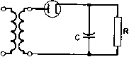 Fig. 78. Capacitor filter. To obtain less voltage variation or ripple amplitude, after the limiting capacitor size has been reached, an inductive reactor may be employed. It may be placed on either the rectifier or the load side of the capacitor, depending on whether the load resistance R is high or low respectively. See Figs. 79(a) and (b). In the former, the voltage Eac has less than the average value QAoEac, because the inductor delays the build-up of current during the positive half-cycle of voltage, and yet the inductor in this case should have a high value of reactance Xj compared to the capacitive reactance Xr, in order to filter effectively. When R is low, reactance Xf, should be high compared to R. 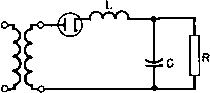 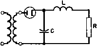 (a) (b) Fig. 79. (a) Inductor-input filter; ib) capaciLor-input filter. In Fig. 79(a) the ripple amplitude across R is -Хс/{Хь - Xc) times the amplitude generated by the rectifier, if R is high compared to Xc-Also, in Fig. 79(6), the ripple amplitude across R is R/X times the ripple obtained with capacitor only. R here is small compared to X. Large values of inductance are required to cause continuous current flow when the inductor is on the rectifier side of the capacitor in a half- wave rectifier circuit. Since current tends to flow only half the time, the rectified output is reduced accordingly. This difficulty is eliminated by the use of the full-wave rectifier of Fig. 80. The alternating 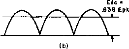 Fig. 80. (a) Single-phase full-wave rectifier; (b) rectified full-wave voltage. components of the output voltage have a fundamental frequency double that of the supply, and the amplitudes of these components are much less than for the half-wa\e rectifier. The higher ripple frequency causes L and С to be doubly effective; the smaller amplitude results in smaller percentage of ripple input to the filter. Current flow is continuous and Eir has double the value that it had in Fig. 77. For these reasons, this type of rectifier is лvidely used. A full-wave rectifier uses only one-half of the transformer winding at a time; that is, Ec is only half the transformer secondary voltage. A circuit which utilizes the whole of this voltage in producing Eac is the single-phase bridge rectifier shown in Fig. 81. The output voltage relations are the same as those of Fig. 80(b). Although this circuit requires more rectifying tubes, it eliminates the need for a transformer midtap. 48. Polyphase Rectifiers. The effect of rectifying more than one phase is to superpose more Aoltages of the same peak value but in different time relation to each other. Figures 82(a) and (6) give a comparative picture of the rectified output voltage for three-phase half-wave and full-wave rectifiers. Increasing the number of phases increases the value of Ec increases the frequency of the alternating components, and decreases the amplitude of these components. Ripple frequency is p times that of the unrectified alternating voltage, p being 1,2,3, and 6 for the respective waves. Roughly speaking, p may be taken to represent the number of phases, provided that due allowance is made for the type of circuit, as in Fig. 83. Rectifiers wnth p = 3 or 6 are deri\ed from three-phase supply lines, and, by special connections, rectifiers with p - 9, 12, or more are obtained. 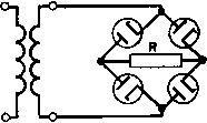 Fig. 81. Bridge rectifier. 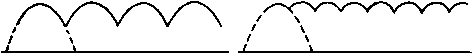 THREE-PHASE HALF WAVE THREE PHASE FULL WAVE OR DOUBLE Y SIX PHASE (0) (bj Fig. 82. Polyphase rectifier output waves. Ripple voltage for any of these rectifiers can be found by the Fourier relation: An = - I /(0 cos nu)t dt (45) where An = amplitude of nth ripple harmonic T = ripple fundamental period t = time (with peak of rectified wave as t = 0) Ш = 2тг/ Tp = 2ir X supply line frequency /(/) = ripple as a function of time - Epk cos o}t, T/2 > o)t> - T/2. The voltage peak is chosen as i = 0 to obtain a symmetrical function f{t) and eliminate a second set of harmonic terms like those in equation 45, but with sin 7io>t under the integral. Ripple amplitude is given in Fig. 83 for the ripple fundamental, and second and third harmonics with reactor-input filters. In this curve, the ratio Pj of ripple amplitude to direct output voltage is plotted against the number of phases p. It should be noted that Pa diminishes by a considerable amount for the second and third harmonics. In general, if a filter effectively reduces the percentage of fundamental ripple across the load, the harmonics may be considered negligibly small. 49. Multistage Filters. In the inductor-input filter shown in Fig. 79(a), the rectifier is a soiuce of non-sinusoidal alternating voltage connected across the filter. It is possible to replace the usual circuit representation by Fig. 84(a). For any harmonic, say the nth, the voltage across the whole circuit is the harmonic amplitude An, and the voltage across the load is PrE,ic, Pr being ripple allowable across the load, expressed as a fraction of the average voltage. Since the load The frequency of any ripple harmonic is mp, where m is the order of the harmonic. < о о о ш 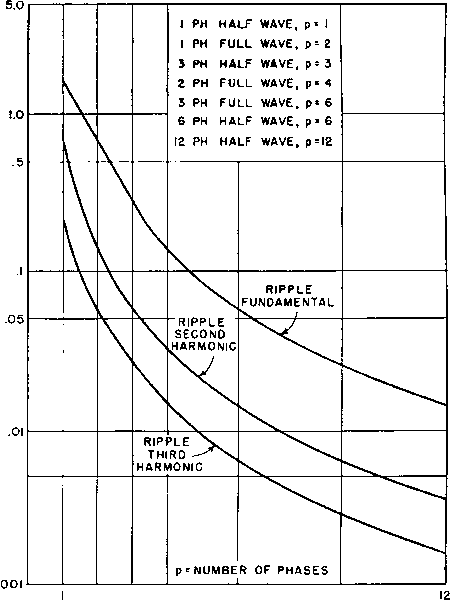 .005 2 3 4 6 9 Fig. 83. Rectifier ripple voltage. p An XXc r 4Xc-3Xc (a) (b) (c) Fig. 84. Inductor-input filter circuits. Xn X( From the type of rectifier to be used, and the permissible amount of ripple in the load voltage, it is possible to determine the ratio of inductive to capacitive reactance. When the magnitude Pr must be kept very small, the single-stage filter of Fig. 84(a) may require the inductor and the capacitor to be abnormally large. It is preferable under this condition to split both the inductor and the capacitor into two separate equal units, and connect them like the two-stage filter of Fig. 84(6). A much smaller total amount of inductance and of capacitance will then be necessary. For this filter Pb \ Xc / Xl and Xc being the reactances of each inductor and capacitor in the circuit. Likewise, the three-stage filter of Fig. 84(c) may be more practicable for still smaller values of Pr. In the latter filter, ~\ Xc ) (48) and, in general, for an n-stage filter, - XV\ (49) It is advantageous to use more than one stage only if the ratio Pa/Pr is high. That the gain from multistage filters is realized only for certain values of Pa/Pr is shown by Fig. 85. The lower curve shows the relation between Pa/Pr and Xl/Xc for a single-stage filter. The second curve shows the increase in Pa/Pr gained by splitting up the same amount of L and С into a two-stage filter; as indicated in Fig. 84(b), the inductor and capacitor both have one-half their lumped value. The upper curve indicates the same increase for a three-stage filter, each inductor and capacitor of which have one-third resistance R is high compared to Xc, the two voltages are nearly in phase, and they bear the same ratio to each other as their respective reactances, or X,-Xc X, of their lumped or single-stage filter value. The attenuation in multistaging is enormous for high XjJXc, For lower ratios there
100,000 50,000 10,000 5000 о 1000 Ш < О l о a: о Ш -I Q. Q. lo. 100 150 200 inductive reactance (lumped values) capacitive reactance Fig. 85. Attenuation in one-, two-, and three-stage filters. may be a loss instead of a gain, as shown by the intersection of the two upper curves. These curves intersect the lower curve if all are prolonged further to the left. This may be a puzzling condition; but consider that, for X/Xc =r 50 in the single-stage filter the ratio is VsXl/3X(, or % in tiie three-stage filter; the rather small advantage in the latter is not difficult to account for. Other factors may influence the number of filter stages. In some applications, modulation or keying may require that a definite size of filter capacitor be used across the load. Usually these conditions result in a single-stage filter, where otherwise more stages might be most economical. Table VII (p. 62) shows filter reactors in the negative lead, which may be either at ground or high potential. If low ripple is required in the filtered output, it is usually preferable to locate the filter reactors in the high-voltage lead. Otherwise, there is a ripple current path through the anode transformer winding capacitance to ground which bypasses the filter reactor. Ripple then has a residual value which cannot be reduced by additional filtering. In the three-phase, zigzag, full-wave circuit, with center tap used for half-voltage output, separate reactors should be used in the positive leads; placing a common reactor in the negative lead introduces high amplitude ripple in the high-voltage output. In rectifiers with low ripple requirements, both filament and anode windings should be accurately center-tapped to avoid low-frequency ripple, which is difficult to filter. Three-phase leg voltages should be balanced for the same reason. 50. Capacitor-Input Filters. One of the assumptions implied at the beginning of this chapter, namely, that transformer and rectifier voltage drops are negligibly small, cannot usually be made when capacitor-input filters are used, because of the large peak currents drawn by the capacitor during the charging interval. Such charging currents drawn through finite resistances affect both the d-c output voltage and the ripple in a complicated manner, and simple analysis such as that given for inductor-input filters is no longer possible. Figure 86 is a plot of the ripple in the load of capacitor-input filters with various ratios of source to load resistance, and for three types of single-phase rectifiers. These curves are useful also when resistance is used in place of an inductor at the input of a filter, ш is 2w times the a-c supply frequency, С is the capacitance, is the load resistance, and jR the source resistance. When L-C filter stages follow a capacitor-input filter, the ripple of the latter is reduced as in Fig. 85, except that the value of Рд must be taken from Fig. 86. When an R-C filter stage follows any type of filter, rlOO 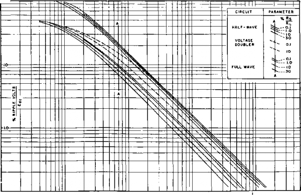 Ю 100 OJCR; (С IN FARADS R. IN OHMS) Fig. 86- Rms ripple voltage of capacitor-input filters. ООО the ripple is reduced in the ratio R/Xc represented by the R-C stage. 51. Rectifier Regulation. The regulation of a rectifier comprises three distinct components: 1. The d-c resistance or IR drop. 2. The commutation reactance or IX drop. 3. The capacitor charging effect. The first component can be reduced to a small value by the use of tubes, transformers, and inductors having low resistance. Mercury- 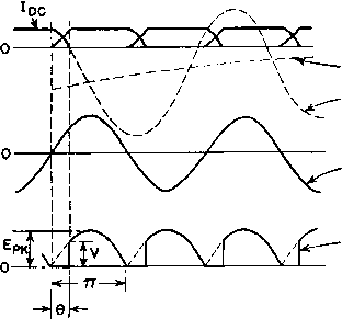 AXIS OF Igc SHORT CIRCUIT CURRENT Цс UNRECTIFIED A-C VOLTAGE RECTIFIED VOLTAGE Fig. 87. Commutation current effect on rectifier voltage. vapor tubes are of noteworthy usefulness in this respect, as the internal voltage drop is low and almost independent of load current variations. Commutation reactance can be kept to a low value by proper transformer design, particularly where the ratio of short-circuit current to normal load is high. During part of each cycle, both tubes of a single-phase full-wave rectifier are conducting. During this interval one tube loses its current and the other one builds up to normal current. Because of the inevitable reactance in the transformer, this change does not take place immediately but during an angle 9 as in Fig. 87. Short-circuit current is initiated which would rise as shown by the dotted lines of Fig. 87, if it could pass through the rectifier tubes; it prevents the rectified voltage wave from retaining its normal shape, so that for a portion of each cycle the rectified output is zero. Let the transformer winding resistance be temporarily neglected; if the current could rise to maximum, the short-circuit value would be 2EpTt/X, луЬеге X is tiie leakage reactance of the whole secondary, but it is limited by the rectifier to /(/(.. The short-circuit current rises to (1 - cos в) times maximum in the commutation period, or [2Ej,k{y - cos в)]/Х = Idc The average voltage from zero to the re-ignition point 1 is {Ерь/тг){1 ~ cose) Combining these relations gives, for the average voltage cut out of the rectified voltage wave by commutation, Fav = hcX/2 (50) By similar reasoning, the commutation reactance drop for polyphase rectifiers is VldcX/2ir (51) where X - the transformer leakage reactance from line to neutral on the secondary side, and p = the number of phases in Fig. 83. In this formula, the leakage reactance per winding is associated with the voltage across that winding. This is accurate when each phase is supplied by a separate transformer. But it fails for p =2 in the single-phase full-wave rectifier, using one plate transformer, where half of the secondary voltage is rectified each half-cycle. In such a rectifier, during commutation the whole secondary \4)ltage is effective, and so is the leakage reactance of the whole secondary. This reactance has 4 tunes the leakage reactance of each secondary half-winding, but only twice the half-winding voltage acts across it. Hence ecjuation 50 must be used for the single-phase rectifier; here A = the reactance of the entire secondary. When high winding resistance limits short-circuit current, commutation has less effect than equation 50 would indicate. This condition prevails in small rectifiers; the IX drop is negligibly small because of the small transformer dimensions. For example, in the plate transformer designed in Fig. 58 the leakage inductance is 0.166 henry. The commutation reactance drop is, from equation 50, 0.115 X 0.166 X 27г X 60/27г = 1.15 volts or 0.1 per cent. This is negligible compared to the 3.7 per cent regulation calculated in Fig. 58. In this case the short-circuit current would be limited by winding resistance rather than by leakage inductance. 1 ... 9 10 11 12 13 14 15 ... 38 |
|||||||||||||||||||||||||||||||||||||||||||||||||||||||||||||
|
© 2026 AutoElektrix.ru
Частичное копирование материалов разрешено при условии активной ссылки |