 |
 |
 |
| Главная Журналы Популярное Audi - почему их так назвали? Как появилась марка Bmw? Откуда появился Lexus? Достижения и устремления Mercedes-Benz Первые модели Chevrolet Электромобиль Nissan Leaf |
Главная » Журналы » Transformer elementary form 1 ... 10 11 12 13 14 15 16 ... 38 In large rectifiers, all rectifier components have low losses to prevent power wastage or overheating, and the IR drop is a very small percentage of the total. At the same time, a large transformer requires careful design in order to keep the IX drop reasonably small. Therefore, in large rectifiers the IX drop is the dominant cause of regulation. An example with 60 kva rating has 0.7 per cent IR drop and 6 per cent IX drop. In medium-size rectifiers the IR and IX drops may be of equal, or at least comparable, value. In such rectifiers these two components of 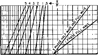 3 2 1 0 0.1 0.2 0.3 0,4 total regulation Х^П Fig. 88. Increase in rectifier regulation due to transformer reactance. regulation do not add arithmetically. Commutation interval в, Fig. 87, depends on the short-circuited reactance when resistance is negligible, but if resistance is appreciable в is related to the ratio X/R exponentially. The increase in regulation caused by commutation reactance may be found from Fig. 88, in terms of d-c output voltage Eac- In this figure the regulation of three widely used rectifiers (single-phase full-wave, three-phase half-wave, and three-phase full-wave) is given in a manner which enables one to proceed directly from the IR component of regulation to total regulation. X and R are ohms per phase except X/R ratio is for the луЬо1е secondary in single-phase full-wave rectifiers. R in X/R ratio includes primary R in all cases. R in IcR/Eac is for two windings in three-phase full-wave rectifiers. To obtain total regulation, project lacR/Edc vertically to one-phase or three-phase line. Project this point to the left to proper X/R line. Abscissa at left gives total regu- 1 See Mercury-Arc Rectifiers and Their Circuits, by D. C. Prince and P. B. Vogdes, McGraw-Hill Book Co., New York, 1927, p. 216. Jdc = 1 amp R R = 60 ohms IdcR 60 X = 120 ohms Edc 2,000 = 3 per cent Total regulation = 1.68 X 3 = 5.04 per cent. If the IX regulation had been added directly to IR it would be 6 per cent + 3 per cent = 9 per cent, and the calculated regulation would be nearly 4 per cent higher than actual. 52. Capacitor Effect. If the rectifier had no filter capacitor, the rectifier would deliver the average value of the rectified voltage wave, less regulation components 1 and 2 of Section 51. But with a filter capacitor, there is a tendency at light loads for the capacitor to charge up to the peak value of the rectified wave. At zero load, this amounts to 1.57 times the average value, or a possible regulation of 57 per cent in addition to the IR and IX components, for single-phase full-wave rectifiers. This effect is smaller in magnitude for polyphase rectifiers, although it is present in all rectifiers to some extent. Suppose that the rectifier circuit shown in Fig. 80 (a) delivers single-phase full-wave rectifier output as shown in Fig. 80(6) to an inductor-input filter and thence to a variable load. In such a circuit, the filter inductor keeps the capacitor from charging to a value greater than the average Ецс of the rectified voltage wave at heavy loads. At light loads the d-c output voltage rises above the average of the rectified wave, as shown by the typical regulation curve of Fig. 89. Starting at zero load, the d-c output voltage Eq is 1.57 times the average of the rectified wave. As the load increases, the output voltage falls rapidly to Ei as the current h is reached. For any load greater than 7i, the regulation is composed only of the two components IR and IX. It is good practice to use a bleeder load h so that the rectifier operates between Ii and /2. Filter elements Xl and Xc determine the load Ii below which voltage rises rapidly. The filter, if it is effective, attenuates the a-c ripple voltage so that across the load there exists a d-c voltage with a small ripple voltage superposed. A choke-input filter attenuates the harmonic voltages much more than the fundamental, and, since the harmonics are smaller to begin with the main function of the filter is lation. An example is indicated by the dotted line. In this example, the rectifier is three-phase full-wave. Eac = 2,000 volts X to take out the fundamental ripple voltage. This has a peak value, according to Fig. 83, of 66.7 per cent of the average rectified d-c voltage for a single-phase full-wave rectifier. Since this ripple is purely a-c it encounters a-c impedances in its circuit. If we designate the choke impedance as Xl, and the capacitor impedance as X both at the fundamental ripple frequency, the impedance to the fundamental component is Хь - Xc, the load resistance being negligibly high compared to Xo in an effective filter. The d-c voltage, on the other hand, produces a current limited mainly by the load resistance, provided that the choke IR drop is small. 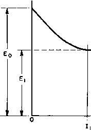 Fig. 89. Rectifier regulation curve. A-c and d-c components are shown in Fig. 90, with the ripple current laG superposed on the load direct current Ic- If the direct current is made smaller by increased load resistance, the a-c component is not affected because load resistance has practically no influence in determining its value. Hence a point will be reached, as the d-c load current is diminished, where the peak value of ripple current just equals the load direct current. Such a condition is given by d-c load 7i which is equal to lao- If the d-c load is reduced further, say to the value /a;, no current flows from the rectifier in the interval A-B of each ripple cycle. The ripple current is not a sine wave, but is cut off on the lower halves, as in the heavy line of Fig, 91. Now the average value of this current is not I but a somewhat higher current ly. That is, the load direct current is higher than the average value of the rectified sine wave voltage divided by the load resistance. This increased current is caused by the tendency of the capacitor to charge up to the peak of the voltage wave between such intervals as A-B\ hence the term capacitor effect which is appUed to the voltage increase. The limiting value of voltage is the peak value of the rectified voltage, which is 1.57 times the sine-wave aAerage, at zero load current. 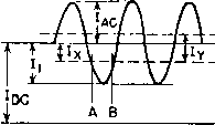 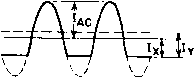 Fig. 90. A-c and d-c components of filter current. Fig. 91. Capacitor effect at light load. To prevent capacitor effect the choke must be large enough so that Jac is equal to or less than the bleeder current ly. This consideration leads directly to the value of choke inductance. The bleeder current Ix is Et/Ri, where Ri is the value of bleeder resistance. The ripple current is the fundamental ripple voltage divided by the ripple circuit impedance, or 0.6671 Xl - Xc Equating Ii and lac we have, for a single-phase full-wave rectifier, Rl = Xl - Xc 0.667 (52) Here we see that the value of capacitance also has an effect, but it is minor relative to that of the choke. In a well-designed filter, the choke reactance Хь is high compared to Xc- Therefore, the predominant element in fixing the value of Ri (and of /i) is the filter reactor. Polyphase rectifiers have similar effects, but the rise in voltage is not so great because of the smaller difference between peak and average d-c output. The bleeder resistance for eliminating capacitor effect can be found in general from Хтл~ Xc Rl =- (53) here Pi is the fundamental ripple peak amplitude from Fig. 83, and Xl and Xc are the filter reactances at fundamental ripple frequency. Between load Ii and zero load, the rate of voltage rise depends upon the filter. Figure 92 shows the voltage rise as a function of the ratio [Xl - Xc)/Rl for a single-phase full-wave rectifier. A curve of ripple in terms of ripple at full load is given. Figure 92 is a plot of experimental data taken on a rectifier with IR -\- IX regulation of 5 per cent. Reactances Xl and Xq are computed for the fundamental ripple frequency. Capacitor-input filters have the voltage regulation curves shown in Figs. 50, 51, and 53) (pp. 64, 65, and 68) for their respective circuits. At light loads these filters may give reasonably good regulation, but it Ш to d Ш > о m < Ш 20 z *S 0
0.2 0,4 0.6 0.8 Xl~Xc Fig. 92. Voltage rise in single-phase full-wave rectifier at light loads. is possible to get very poor regulation at heavier loads, as can be seen from the curves. Rectifier series resistance plays an important part in the voltage regulation of this type of filter. The effect of anode transformer leakage inductance can be found from Fig. 92. 53. Tuned Rectifier Filters. Sometimes an inductor-input filter is tuned as in Fig. 93. The addition of capacitor Ci increases the effective reactance of the inductor to the fundamental ripple frequency. Both regulation and ripple of this type of filter are improved. The filter is not tuned for the ripple harmonics, so the use of high-Q filter inductors is unnecessary. An increase in effectiveness of the filter inductor of about 3 to 1 can be realized in a single-phase full-wave rectifier circuit. Tuned filters are less effective with three-phase rectifiers because slight phase unbalance introduces low-frequency ripple which the filter does not attenuate. Filters may be tuned as in Fig. 94, where the filter capacitor Ci is connected to a tap near the right end of inductor L, and the other filter capacitor C2 is chosen to give series resonance and hence zero reactance across the load at the fundamental ripple frequency. Because of choke losses, the impedance across Rt is not zero, but the resulting ripple across load resistor Rl can be made lower than without Fig. 93. Shunt-tuned filter. Fig. 94. Series-tuned filter. the use of capacitor Ci. Ripple is attenuated more than in the usual inductor-input filter, but regulation is not substantially different. 54. Rectifier Currents. If the inductor in an inductor-input filter were infinitely large, the current through it would remain constant. If the commutation reactance effect is not considered, the current through each tube of a single-phase rectifier would be a square wave, as shown by 7i and I2 of Fig. 49(a) (p. 63). The peak value of this current wave is the same as the d-c output of the rectifier, and the rms value is 0.707/0. With finite values of inductance, an appreciable amount of ripple current flows through the inductor and effectively modulates Ii and I2, thus producing a larger rms inductor current like the first wave of Table I (p. 16). Capacitor-input filters draw current from the rectifier only during certain portions of the cycle, as shown in Fig. 49(6). For a given average direct current, the peak and rms values of these current \vaves arc much higher than for inductor-input filters. Values for the single-phase rectifiers are given in Fig. 52 (p. 66). If an L-C filter stage follows the input capacitor, tlie inductor rms current is the output direct current plus the ripple current in quadrature. Polyphase rectifiers are ordinarily of the choke-input type, because they are used mostly for larger power, and therefore any appreciable amount of series resistance cannot be tolerated. For this reason, the low IR drop tubes, such as mercury-vapor rectifiers, are commonly used. Such tubes do not possess sufficient internal drop to restrict the peak currents drawn by capacitt)r-input filters to the proper values. In a shunt-tuned power supply filter such as shown in Fig. 93, the current drawn from the rectifier is likely to be peaked because two capacitors Ci and С2 are in series, without intervening resistance or inductance. This peak quickly subsides because of the influence of inductor L, but an oscillation may take place on top of the tube cur- rent wave as shown in Fig. 95. The rectifier tube must be rated to withstand this peak current. At the end of commutation the voltage 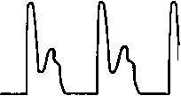 Fig. 95. Anode current with shunt-tuned filter. jumps suddenly from zero to V (Fig. 87). Peak rectifier current may be as much as Ipk = V/coL, (54) Lg is half the transformer leakage inductance, and ш = 2тг X frequency of oscillation determined by Lg in series with Ci and C2. This peak current is superposed on lac- It flows through the anode transformer and tube, but the current in choke L (Fig. 93) is determined by ripple voltage amplitude and choke reactance. Series resistance Rg reduces this peak current to the value Ipk - (55) It is obtained by applying a step function voltage to the series RgLgC circuit. The criterion for oscillations is Rs < 2  (56) where С is the capacitance of Ci and С2 in series. Many rectifier tubes have peak current ratings which must not be exceeded by such currents. Currents shown in Table VII (p. 62) and Figs. 49 and 95 are reflected back into the a-c power supply line, except that alternate current waves are of reverse polarity. Small rectifiers have little effect on the power system, but large rectifiers may produce excessive interference in nearby telephone lines because of the large harmonic currents inherent in rectifier loads. High values of commutation reactance reduce these line current harmonics, but, since good regulation requires low commutation reactance, there is a limit to the control possible by this means. A-c line filters are used to attenuate the line current harmonics. A large rectifier, with three-phase series resonant circuits designed to eliminate the eleventh, thirteenth, seventeenth, and nineteenth harmonics of a 60-cycle system, is shown in Fig. 96. Smaller rectifiers sometimes have filter sections such as A-c SUPPLY 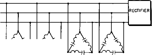 1140 CY 1020 CY 780 CY RESONANT FILTERS 660 CY Fig. 96. A-e lino filter for large power rectifier. those in Fig. 97; these are rarely used in large installations because of the excessive voltage regulation introduced by the line inductors. Filters designed to keep r-f currents out of the a-c lines are often LINE INDUCTORS A-C SUPPLY RECTIFIER SHUNT CAPACITORS Fig. 97. A-c line filter for medium-sized power rectifier. used with high-voltage rectifiers. Even if the anode transformer has low radio influence, commutation may cause r-f currents to flow in the supply lines unless there is a filter. 55. Rectifier Transients. The shunt-tuned filter currents mentioned in the preceding section are transient. Since the tube current is cut off during each cycle, a transient current may occur in each cycle. When power is first applied to the rectifier, another transient occurs, which may be smaller or larger than the cyclic transient, depending on the filter elements. In reactor-input filters the transient current can be approximated by the formula given in Section 54 for a step function applied to the series circuit comprising filter L and С plus Д^. This circuit is valid because the shunting effect of the load is slight in a well-proportioned filter. In capacitor-input filters, the same method can be used, but here the inductance is the leakage inductance of the anode transformer. Therefore, equation 55 applies, except that the maximum step function voltage is Ер]. Transients which occur when power is first applied differ from cyclic transients in that they are spasmodic. Power may be applied at any instant of the alternating voltage cycle, and the suddenly impressed rectifier voltage ranges from zero to Ep. Starting transients are difficult to observe on an oscilloscope because of their random character. It is necessary to start the rectifier several times for one observation of maximum amplitude, and the trace is faint because it appears for a very brief time. Excessive current inrush, which occurs when a power transformer is connected to a supply fine, plagues rectifier design. The phenomenon is associated with core saturation. For example, suppose that the core induction is at the top of the hysteresis loop in Fig. 18 (p. 24) at the instant when power is removed from the rectifier, and that it decreases to residual value Br for H - 0. Suppose that the next application of power is at such a point in the voltage cycle that the normal induction would be В^. This added to Br requires a total induction far above saturation value; therefore heavy initial magnetizing current is drawn from the line, limited only by primary winding resistance and leakage inductance. This heavy current has a peaked wave form луЬ1сЬ may induce momentary high voltages by internal resonance in the secondary coils and damage the rectifier tubes. Or it may trip a-c overload relays. The problem is especially acute in large transformers with low regulation. A common remedy is to start the rectifier with external resistors in the primary circuit and short-circuit them a few cycles later. Some rectifiers are equipped with voltage regulators which reduce the primary voltage to a low value before restarting. A-c line transients may cause trouble in three-phase rectifiers, especially those having balance coils, by shifting the floating neutral voltage. Filters like that in Fig. 97 prevent such transients from appearing in the rectified output. In some applications the load is varied or removed periodically. Examples of this are keyed or modulated amplifiers. Transients occur 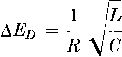 (57) where Д£?д is the transient dip expressed as a fraction of the steady-state voltage across R, and L, C, and R are as shown in Fig. 79(a). The accuracy of this approximation is poor for dips in transient voltage greater than 20 per cent. Although the tendency for key clicks in -1 the signal may be reduced by attention to the d-c supply filter elements, the clicks L may not be entirely eliminated. Where key-click elimination is necessary, some sort of key-click filter is used, of which Fig. 98 is an example. This filter has то key circuit inductance and capacitance enough to ig. 98. Key-click filter, round off the top and back of a wave and eliminate sharp, click-producing corners. Figure 99 is an oscillogram showing a keyed wave shape with and without such a filter. In a choke-input filter, voltage surges are developed across the choke under the following conditions: when the load is applied (key down) or removed (key up), causing respectively a momentary drop or rise in plate voltage. If the load is a device which transmits intelligence, the variation in filter output voltage produced by these transients results in the following undesirable effects: 1. Modulation of the transmitted signal. 2. Frequency variation in oscillators, if they are connected to the same plate supply. 3. Greater tendency for key clicks, especially if the transient initial dip is sharp. 4. Loss of signal power. A filter which attenuates ripple effectively is normally oscillatory; hence damping out the oscillations is not practicable. Nor would it remedy the transient dip in voltage, which may increase with non-oscillatory circuits. The filter capacitor next to the load should be large enough to keep the voltage dip reasonably small. An approximation for transient dip in load voltage which neglects the damping effect of load and series resistance is 1 ... 10 11 12 13 14 15 16 ... 38 |
|
© 2026 AutoElektrix.ru
Частичное копирование материалов разрешено при условии активной ссылки |