 |
 |
 |
| Главная Журналы Популярное Audi - почему их так назвали? Как появилась марка Bmw? Откуда появился Lexus? Достижения и устремления Mercedes-Benz Первые модели Chevrolet Электромобиль Nissan Leaf |
Главная » Журналы » Transformer elementary form 1 ... 11 12 13 14 15 16 17 ... 38 1. Ripple Voltage. With large rectifier commutation angles, or with grid-controlled rectifiers, a surge occurs once each ripple cycle. In the limit, this surge equals the rectifier peak voltage. 2. Initial Starting Surge. This surge adds to output d-c voltage. Under the worst conditions it raises the voltage at this point to twice normal and occurs every time rectifier plate voltage is applied. 60 CYCLES 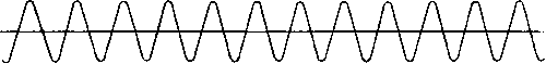 KEYED WAVE, NO FILTER ZERO KEYED WAVE WITH FILTER 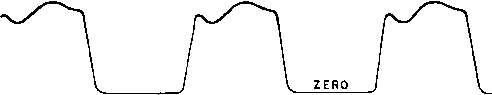 Fig. 99. Keyed wave shape with and without key-click filter. 3. Keying or Modulation Transient. Surge value depends upon constants L, С, and Rl, and is limited by considerations of wave shape. This occurs each time the key is opened or closed, or load is varied. 4. Short-Circuit Surge. If load Rl is suddenly short-circuited, it causes full d-c voltage to appear across the filter reactor until the circuit breaker opens. This occurs occasionally. Rectifiers are sometimes arranged so that, if the short circuit persists, the circuit breaker recloses 3 times and then remains open. 5. Interruption of Reactor Current. This surge voltage is limited only by losses and capacitance of the circuit, and it may be large, as shown by Fig. 73. Unless the reactor is designed to produce this voltage, it occurs only through accident. Conceivably, surges 1, 2, and 3 may occur simultaneously and add arithmetically. A reactor insulated to лvithstand surges 1 plus 2 plus 3 also would withstand surge 4. A reasonable value of peak surge voltage comprising these factors is 2/4 times the full d-c working voltage. If surges 1 and 5 are too much for reasonable insulation, the reactor is protected by a gap or other means. If a rectifier is disconnected from the supply line while the load is off, interruption of plate transformer peak magnetizing current may cause high voltages to appear at random in the windings in much the same way as reactor current interruption causes high voltages. This is especially true if the transformer operates at high core induction. The effect is partly mitigated by the arc energy incident to the opening of the disconnecting switch. But unless the plate transformer is insulated specifically to prevent dangerously high voltages, protective elements may have to be added in a rectifier subject to switching at light loads. The necessity for such protection may be estimated from exciting volt-ampere data plus the curves of Fig. 73. Insufficient attention sometimes is given to the manner in which power supply lines are brought into buildings. This is particularly important where a rectifier is supplied by o\erhead high-voltage lines. Because of their relatively high surge impedance, lightning and switching surges occurring on such lines may cause abnormally high voltages to appear in a rectifier and break down the insulation of transformers or other component parts. The likelihood of such surges occurring should be taken into account before the transformers are designed. Underground cable power lines impose much less severe hazards: first because they are protected from lightning strokes, and second because they have much lower impedance (about one-tenth that of overhead lines). Surges on these cables have much lower values compared to those on overhead lines carrying the same rated voltage. Protection against these surges varies with the type of installation. The best protection of all is provided by an indoor power system with an underground cable connecting it to the rectifier. Good protection is afforded by oil-insulated outdoor surge-proof distribution transformers, stepping down to the rectifier a-c power supply voltage, with an underground cable between the distribution transformer and rectifier. No protection at all is provided when overhead lines come directly into the rectifier building. With the trend to dry-type insulation, it is desirable to use lightning arresters on overhead lines where they enter the building. Because of their low impulse ratio, dry-type transformers require additional arresters inside the building. When a line surge is discharged by a lightning arrester, there is no power interruption. 56. Rectifier Filter Charts. From the preceding sections, it can be seen that various properties of rectifier filters, such as ripple, regula- tion, and transients, may impose conflicting conditions on rectifier design. To save time in what otherwise would be a laborious cut-and-try process, charts are used. In Fig. 100 the more usual filter properties are presented on a single chart to assist in arriving at the best filter directly. This chart primarily satisfies ripple and regulation equations 46 and 53 for a choke-input filter. Abscissa values of the right-hand scale are bleeder conductance in milliamperes per volt, and of the left-hand scale, filter capacitance in microfarads. Ordinates of the lower vertical scale are inductance in henrys. Lines representing various amounts of ripple in the load are plotted in quadrant I, labeled both in db and rms per cent ripple. In quadrant II, lines are drawn representing different types of rectifiers and supply line frequencies. A similar set of lines is shown in quadrant IV. Two orthogonal sets of lines are drawn in quadrant III. Those sloping downward to the right represent resonant frequency of the filter L and C, and also load resistance Вь- The other set of lines is labeled л/L/C, which may be regarded as the filter impedance. It can be shown that the transient properties of the filter are dependent upon the ratio of У L/C to R- The L scale requires a correction to compensate for the fact that ripple is not exactly a linear function of L but rather of - Xc. The curves in the lower part of quadrant IV give the amount of correction to be added when the correction is greater than 1 per cent. Instructions for Using Chart 1. Assume suitable value of bleeder resistance or bleeder current Д in millamperes per volt of Е^с- This is also steady-state peak ripple current in milliamperes. 2. Trace upward on assumed bleeder ordinate to intersect desired value of load ripple, and from here trace horizontally to the left to diagonal line for rectifier and supply frequency used. Directly under, read value of C. 3. Trace downward on same assumed bleeder ordinate to intersect diagonal line below for rectifier and supply frequency, and read value of L. 4. From desired ripple value, determine correction for L on graph at lower right, and add indicated correction to value of L. 5. Using corrected value of L and next standard value of C, find intersection in third quadrant, and read maximum resonant frequency fr. 6. Using same values of L and С as in 5, read value of ratio У L/C. 7. Under intersection of л/L/C with load resistance Ej, read values of the four transients illustrated in Fig. 101 (in per cent). £xampZe (shown dotted). Three-phase full-wave 60-cycle rectifier; Edc = 3,000 v; h = 1 amp; 7i = 96 ma; load ripple = - 50 db; balanced line. Solution: Bleeder ma/volt = 0.032. С = 4.5 fii (use 5 f). Scale value of L = 0.78 h; corrected value = 0.82 h. Resonant frequency = 75 cycles. Load resistance Rl = 3,000 ohms. im = 7/2 = 7 amp; AEd =12 per cent; АЕц = 15 per cent; AEs = 80 per cent. In polyphase rectifiers the possibility exists of enough phase unbalance to impress a voltage on the filter having a frequency lower than the normal fundamental ripple frequency. If the filter L and С resonate near the unbalance frequency, then excessive ripple may be expected. Conversely, the L and С should have a resonant frequency lower than the unbalance frequency to avoid this trouble. Quadrant III of the chart has a series of lines labeled jr, and the intersection of L and С thereon indicates this resonant frequency. It should be no higher than the value given in the small table on the chart if excessive ripple is to be avoided. This table is based on 2 per cent maximum unbalance in the phase voltages. For most practical rectifier filters, transient conditions fall within the left-hand portion of the third quadrant. The other conditions sometimes help in the solution of problems in which L and С are incidental, e.g., the leakage inductance and distributed capacitance of a plate transformer. Although the chart applies directly to single-stage, untuned filters with constant choke inductance, it can be used for other types with modifications: (a) Shunt-Tuned Choke per Fig. 93. Figure 100 can be used directly for capacitance C, but, for a given amount of ripple, divide the chart values of inductance by 3 in order to obtain the actual henrys needed in the choke. (b) Swinging Choke. If at light load the filter choke swings to S times the full-load value of henrys, multiply the capacitance obtained from the chart by the ratio S to find the capacitance needed (C ). The 10080 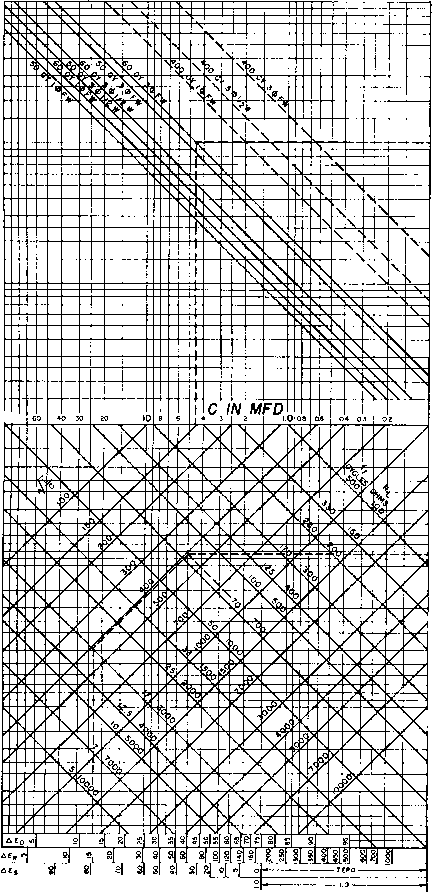 Fig. 100. Choke-input filter chart. RIPPLE =RMS A-C VOLTAGE ACROSS С-гЕ,. 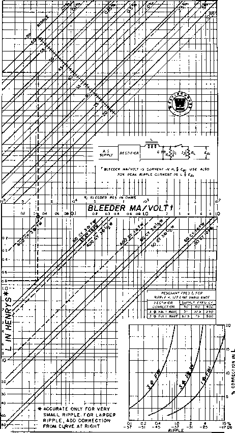 ZERO CHOKE AND RECTIFIER REGULATION ASSUMED L ASSUMED CONSTANT WITH VARYING DIRECT CURRENT D. RIPPLE = SO L0G.0 A-G VOLTAGE ACROSS С 0.70/ Etfr Fig. 100. (Continued) value of L obtained by projecting the bleeder current downwards is the maximum or swinging value. It must be divided by S to obtain the full-load value. Transient conditions then may be approximated by using capacitance (7 and the full-load value of henrys.
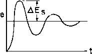 TRANSIENT CONDITIONS WHEN RECTIFIER IS STARTED T AEd 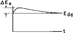 VOLTAGE DIP AEo VOLTAGE RISE AEr TRANSIENT CONDITIONS WITH VARIABLE LOAD Fig. 101. Four transient conditions in choke-input filter circuit and curves. ic) Two-Stage Filters. In a filter лvith two identical stages, Fig. 84(6), the chart can be used if it is recognized that the ripple is that on the load side of the first choke. For example, if the filter consists of two stages both equal to that in the example given for the single-stage filter, the ripple would not be -100 db but -75 db, because of the fact that the rectifier output has (per Table VII) only 4 per cent ripple, which is -25 db. The regulation in a tлvo-stage filter, as far as capacitor effect is concerned, depends upon the inductance of the first choke as in the single-stage filter. Therefore the chart applies directly to the inductance and capacitance of one stage. The peak ripple current likewise depends u})on the inductance of the first choke, regardless of the location of the bleeder resistor. Transients, Ьолуеуег, are more complicated, owing to the fact that the two stages interact under transient conditions. 57. Rectifier Efficiency. Losses in a rectifier consist of transformer, tube, and filter losses. Filament power should be counted as loss, especially when a tube rectifier is compared with a rotating machine 1 See Proc. LR.E., 22, 213 (February, 1934). or metal disk rectifier. In spite of this loss, a high-voltage polyphase rectifier of the mercury-vapor or pool type may have 95 per cent efficiency at full load. In contrast, the rectifier for a radio receiver rarely has more than 60 per cent efficiency. Reasons for this low figure are the high tube and reactor IR drops and low transformer efficiency. The filament power, too, is a greater portion of the total. 58. Rectifier Tests. Even though the transformers, chokes, tubes, and capacitors have been tested before assembly of the rectifier, performance tests of the rectifier are desirable. These generally include tests of output, regulation, efficiency, ripple, and input kilovolt-amperes or power factor. Accurate meters should be used, and polyphase rectifiers should have balanced supply voltages. Wiring is tested at some voltage higher than normal, preferably with transformers, tubes, and capacitors disconnected to avoid damage during the test. Ordinary care in testing is sufficient except for regulation tests. If the regulation is low, the difference in meter readings at no load and full load may be inaccurate. Differential measurements are sometimes used, such as a voltmeter connected between the rectifier and a fixed source of the same polarity and voltage. Artificial loading of a high-voltage rectifier is often a problem. Water rheostats have been used for this purpose. Load tests, preferably in combination with the transmitter or other apparatus which the rectifier is to supply, are safeguards against field troubles. Operating tests are essential when the load is keyed or modulated, so that overheating or inadequate transformer operation may be detected. Ripple is measured either with a special hum-measuring instrument or with a capacitance-resistance network arranged to block the direct current from the measuring circuit. Capacitance and resistance values in the measuring circuit should be so chosen as to avoid influencing the ripple or loading the rectifier transformer. Sometimes capacitance dividers are used for this purpose. The problem of proper alues becomes particularly critical with high-voltage low-current rectifiers. The effect of stray capacitance is especially important. 5. AMPLIFIER TRANSFORMERS An amplifier is a device for increasing voltage, current, or power in a circuit. The original wave form may or may not be maintained; the frequency usually is. An amplifier may be mechanical, electromechanical, electromagnetic, or electronic in form, or it may be a combination of these. In this chapter the transformer-coupled electronic ampbfier is considered. The amplifier consists of a vacuum tube, or similar device, with transformers, capacitors, and resistors. Input voltage or current is impressed on some element of the tube; this causes higher voltage or current to appear in the output circuit. 59. Amplifier Potentials. Electronic amplifiers are characterized by the use of tubes having three or more elements. In triodes or three-element tubes, the addition of the third element, the grid, alters the CATHODE ANODE 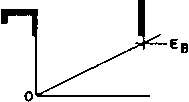 CATHODE GRID ANODE 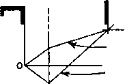 POSITIVE GRID VOLTAGE NEGATIVE GRID VOLTAGE VOLTAGE GRADIENT IN DIODE VOLTAGE GRADIENTS IN TRIODE Fig. 102. Diode and triode voltage gradient. voltage gradient between cathode and anode as shown in Fig. 102. The grid either aids or opposes the flow of electrons from cathode to anode, depending on whether the grid voltage is positive or negative respectively, compared to the cathode, which is shown at zero voltage in Fig. 102. As the grid voltage is made more and more negative, electron flow is diminished and finally stops. At this point the anode current is zero; the condition is called anode current cut-off. If the grid voltage is made more and more positive, eventually further increase in grid voltage causes no additional anode current increase. This condition is called grid saturation. Tetrodes and pentodes have respectively two and three grids. The voltage gradient between cathode and anode is more complex than that indicated in Fig. 102. The advantages to be gained from the additional grids are mentioned below. 60. Transformer-Coupled Amplifiers. Amplifier circuits in which transformers are used can be represented by a circuit similar to that of Fig. 103(a). Here a triode is shown with a voltage во impressed upon the grid, which comprises the grid bias (a constant negative direct voltage) and a superimposed alternating voltage e. Anode 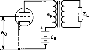 Fig. 103. (a) Transformer-coupled amplifier; (b) equivalent circuit. voltage Ев is supplied from some source through the primary of the transformer, across which appears an alternating voltage вр. The secondary of the transformer is connected to a load Z. Under certain conditions, which will be defined below, this circuit may be simplified to that of Fig. 103 (b). A fictitious alternating voltage ieg is impressed on the circuit, where /л is the tube amplification factor. Internal tube resistance Zo is in series with the load Z, which is reflected by the transformer to the proper value in the primary circuit for tube operation. That is, Zl in Fig. 103(6) is equal to that in Fig. 103(a) only if the transformer has a 1:1 ratio. For any turns ratio, the quotient of two Zs is equal to the (turns ratio) as in equation 7 (p. 8). Note that the winding resistances are regarded as zero, so that, in the absence of a grid signal, full voltage Ев appears on the plate of the vacuum tube. Alternating voltage /ле, causes voltage вр to appear across the load Zl- The voltage is not fi times вд but is related by the following equation: 1 ... 11 12 13 14 15 16 17 ... 38 |
|
© 2026 AutoElektrix.ru
Частичное копирование материалов разрешено при условии активной ссылки |