 |
 |
 |
| Главная Журналы Популярное Audi - почему их так назвали? Как появилась марка Bmw? Откуда появился Lexus? Достижения и устремления Mercedes-Benz Первые модели Chevrolet Электромобиль Nissan Leaf |
Главная » Журналы » Transformer elementary form 1 ... 12 13 14 15 16 17 18 ... 38 (58) Although transformer-coupled amplifiers are used sometimes for voltage amplification, they are used mostly where power output is required of the amplifier and where a good reproduction of the grid voltage is required in the plate circuit. 61. Tuned Amplifiers. Figure 104 shows the circuit for an amplifier in which the output voltage appears across a parallel-tuned circuit.  Fig. 104. Tuned amplifier. This circuit is shown coupled to a load Z. This type of amplifier may be used where large outputs are required, but the voltage вр is not necessarily a reproduction of e, and they are not related as in equation 58. 62. Amplifier Classification. Amplifiers can be divided into classes, depending upon the mode of operation. A class A amplifier is one in which the grid bias and alternating grid voltage are such that anode current fiows continuously. In a class В amplifier the grid bias is almost equal to the cut-off value, so that plate current is nearly zero when no exciting grid voltage is applied. When full alternating grid Altage is applied, plate current flows for approximately one-half of each cycle. A class С amplifier has a grid bias greater than the cut-off value, so that the plate current is zero when no alternating grid voltage is applied and it flows for appreciably less than one-half of each cycle when an alternating grid voltage is applied. These classes are illustrated in Fig. 105, in which the alternating plate current, plate voltage, grid voltage, and grid current are shown with the steady or average values which are, respectively, Ib, Eb, Ec, and Iq. Relative plate and grid voltage amplitudes for these three types of amplifiers are shown in Fig. 105, and other properties are summarized in Table XI. Class A amplifiers are characterized by comparatively high no-signal anode current. Usually the grid never swings positive. Anode cur- PLATE CURRENT PLATE VOLTAGE GRID VOLTAGE GRID CURRENT 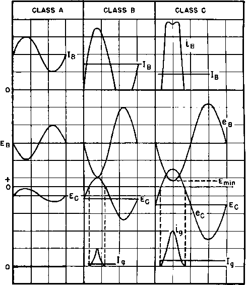 Fig. 105. Amplifier voltages and currents. Table XI. Amplifier Classes Amplifier Class Anode efficiency a. Theoretical maximum 50% b. Practical value for low distortion Output proportional to eg Grid current Ig None Anode current Is Fairly В 78.5% * Up to 30% 40-67% Small eg = Of Ib low 100% с 70-85% t Eb (grid saturated) Large (may ~ Is) eg=Q,lB=0 constant eg = max, I в high eg = max, I в high * These values are for push-pull amplifiers. t With a high-Q tank circuit, the efficiency depends on excitation power.   rent remains comparatively constant, when averaged over a whole a-c cycle. In class В amplifiers, the grid is biased at a greater negative potential so that current is nearly cut off in the absence of a signal. Positive swings of grid voltage result in anode current being drawn; this causes a dip in the residual voltage on the plate of the amplifier. Negative grid swings cause no plate current to flow but do cause a positive plate voltage swing. In class С amphfiers, the grid is biased more negatively still, with the result that plate current flows for less than half a cycle, and mostly when the plate voltage on the tube is at a relatively low value. Grid current in this class of amplifier reaches values comparable to the plate current. Output voltage wave form is maintained by a tuned plate circuit. Operation may sometimes be im-proл^ed by the use of two tubes connected push-pull, as shown in Fig. 106. This is the most common connection for class В amplifiers; also, it is frequently used in class A amplifiers. Intermediate between class A and class В amplifiers are those known as class AB with grid bias and efficiency intermediate between class A and class В amplifiers. Such amplifiers are further subdivided into class ABi and class AB2. Class ABi amplifiers draw no grid current, but the bias voltage is somewhat higher than the class A value and the plate current may be discontinuous during the cycle when grid signal is applied. Class AB2 amplifiers draлv grid current but are not biased as close to cut-off as class В amplifiers. Both class ABi and AB2 amplifiers are commonly used with the push-pull connection. Tube properties such as plate resistance r, amplification factor and mutual conductance may be calculated from data published for each tube in the form of characteristic curves. Operating conditions such as plate- and grid-voltage swings, power output, plate dissipation, and efficiency also arc found from these curves. Theoretical discussions of such data may be found in books on amplifiers. 63. Decibels; Impedance Matching. In amplifier work, the ratio of two voltages -EJi and E2 at the same impedance 1еЛе1 is often stated in decibels (db) according to the definition Fig. 106. Push-pull amplifier.  (60) where L and С are the inductance and capacitance per unit length. If such a line terminates in a pure resistance load equal in ohmic value to Zo, all the power fed into the line appears in the load without attenuation or reflection. This is called matching the impedance of the line. It is very desirable to save audio power and avoid reflections; therefore impedance matching of lines is the usual practice wherever possible. The notion has been extended to include the loading of vacuum tubes, but this is stretching the meaning of the term matching. A vacuum tube has its optimum load impedance, but the value depends upon the conditions of tube operation and is not necessarily the same as the tube internal impedance. Power transmission lines operating at 60 cycles are rarely long enough to act as appreciable source impedances. When a short-circuit or low-impedance fault occurs on the load side of a power transformer, the load current is limited mainly by the transformer short-circuit impedance. In a vacuum-tube amplifier, the load current delivered into a short-circuited load is limited mainly by the vacuum-tube internal resistance rather than by the transformer. At certain frequencies the transformer itself may contribute to low load impedance. But the greatest difference between power and amplifier transformers is the difference in source impedance. Even the use of the word impedance in the two fields of application reflects this difference. In power work, transformer impedance denotes the short-circuit im- db = 20 logio (£1/2) (59) Amplifier voltage gain, transformer ratio, frequency response, and noise levels all may be expressed in decibels. Volume, voltage, or power in decibels must be compared to a reference level; otherwise the term is meaningless. A standard reference level is 1 milliwatt. This is expressed as zero dbm. Across 600 ohms, the voltage for zero dbm is VO-001 X 600 = 0.775 volt; for 20 dbm the voltage is 7.75 volts. Transmission lines at audio and higher frequencies exhibit properties commonly ignored at 60 cycles. Line wavelength, characteristic impedance, and attenuation are important at audio frequencies; so is the matter of matching impedance. If a long transmission line has no attenuation, its characteristic impedance is given by jX + R2 The scalar value of this ratio is found by taking the square root of the sum of quadrature terms: pedance; in amplifier work, the same term refers to the load or source impedance. 64. Amplifier Transformers. The major problem of amplifier transformer design is obtaining proper output when the transformer is operated in conjunction wdth the apparatus for which it is intended. Several factors external to the transformer affect its performance, namely, (1) impedance of the source; (2) linearity of this impedance; (3) impedance of the load; and (4) frequency. The simplest method of dealing with amplifier transformers is an adaptation of the so-called equivalent network which has long been used for power transformers. The transformer that connects the source to its load in Fig. 103(a) may be represented more fully by the diagram of Fig. 107(a). 65. Low-Frequency Response. At low frequencies, the leakage reactances are negligibly small. Resistance Rp may then be combined with Zg to form Ri for a pure resistance source, and Rs with Zl to form J?2 for a resistance load. At low frequencies both source and load are pure resistance, and the circuit may be simplified to that of Fig. 107(b). Here the has been dropped; in other words, a transformer with a 1:1 ratio is shown, referred to the primary side. is the primary open-circuit reactance, or 27г/ times the primary open-circuit inductance (OCL) as measured at low frequencies. If shunt resistance Rr is included in load resistance R2, the circuit becomes like that of Fig. 107(c). Winding resistances are small compared with source and load resistances in well-designed transformers. Likewise, R is high compared with load resistance, especially if core material of good quality is used. Therefore, to a good approximation, in Fig. 107(c), Ri may represent the source impedance and R2 the load impedance. On a 1:1 turns-ratio basis, the voltages E2 and Ei are proportional to the impedances across which they appear or jXA E2 JXn + R2 - = -1- (61) El jXR2 Ki + AMPLIFIER TRANSFORMERS E2 1 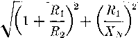 147 (62) Equation 62 holds for any values of К\, R2, and Xn whatsoever, but there are three cases that deserve particular attention: (a) R2 = Ri, (b) R2 =2Ri; and (c) R2= 00. Of these, (a) corresponds to the usual line-matching transformer with the source and load impedances equal; (6) is often recommended for maximum undistorted output of triodes; (c) is realized practically when the load is the grid of a class A Zg Rp Xp Xs/a2 Rs/a2 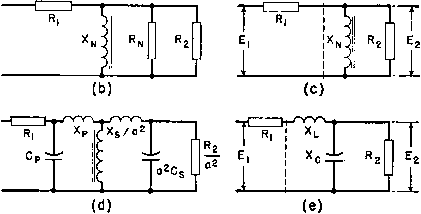 symbols a = RATIO OF SEC. TO PRI. TURNS Cp = PRI. WINDING CAPACITANCE Cs=SEC, WINDING CAPACITANCE Ct=Cp + o2Cs f = ANY AUDIO FREQUENCY ir= RESONANCE FREQ. OF Xl & Xq Rp = PRI. WINDING RESISTANCE Rs-SEC. WINDING RESISTANCE Xl = PRI. NO LOAD (CORE LOSS) EQUIVALENT RESISTANCE PRI. OPEN CIRCUIT REACTANCE PRI. LEAKAGE REACTANCE SEC. LEAKAGE REACTANCE Xp + Xs/qZ TOTAL CAPACITY REACTANCE I 2Trf Ct SOURCE IMPEDANCE LOAD IMPEDANCE Fig. 107. (a) Transformer equivalent circuit; (b) low-frequency equivalent circuit; (c) simplified low-frequency circuit; {d) high-frequency equivalent circuit; (e) simplified high-frequency circuit. 148 ELECTRONIC TRANSFORMERS AND CIRCUITS amplifier. For these cases, equation 62 becomes E. 1 ?1 El (62a) (62b) (62c) These three equations are plotted in Fig. 108 to show low-frequency response as db down from median. The median frequency in an audio transformer is the geometric mean of the audio range; for other transformers it is a frequency at which the ratio Xn/Rx is very large. At median frequency the circuit is properly represented by Fig. 103(b). о Ы о llJ z < о £ О О О CD О 2 3 4 5 6 7 8 9 10 ii 12 13 14
0.4 0.6 0,8 1.0 2.0 4.0 6.0 8.0 10.0 Fig. 108. Transformer characteristics at low frequencies. The equivalent voltage ratio E2/E1 has maxima of 0.5, 0.667, and 1.0 for cases (ct), (6), and (c), respectively, at the median frequency, or for Xn/Ei = 00 in Fig. 108. The higher ОСЬ, the nearer the transformer voltage ratio approaches median-frequency value. The lower the value of loading resistance R2, the lower the equivalent voltage ratio is. The factors 0.5, 0.667, and 1.0 multiplied by the turns ratio, a, give the actual voltage ratio at median frequency. At lower frequencies, the factors diminish. The transformer loaded by the lowest resistance has the best low-frequency characteristic. A transforaier having an open-circuit secondary has twice the voltage ratio and gives the same response at twice the low end frequency of a line-matching transformer of the same turns ratio. Figure 108 is of direct use in determining the proper value of primary OCL. Permissible response deviation at the lowest operating frequency fixes Xjs/Ri and therefore Хдг. At the corresponding frequency, this represents a certain value of primary OCL. As this inductance determines the size and weight of the transformer, the importance of Fig. 108 is evident. If the primary and equivalent (1:1) secondary winding resistance each are 5 per cent of Ei, the total effect will be a decrease of 10 per cent in the median-frequency voltage ratio, in the case of the line-matching transformer, with corresponding decreases at lower frequencies. On the other hand, the primary resistance of an open secondary transformer has no effect upon the median-frequency voltage ratio but has some effect at lower frequencies, whereas the secondary resistance has no effect either at median or at lower frequencies. Hence it is important in the open secondary case, for the sake of low-frequency response, to keep the primary winding resistance low, but the secondary winding resistance may be any value. The maximum number of secondary turns may be determined by the smallest practicable wire size rather than by winding resistance. As the frequency increases, the primary inductive reactance Xn also increases until it has almost no effect upon frequency response. This is true for median frequency in Fig. 108. It is also true for higher frequencies; in other words, the OCL has an influence only on the low-frequency end of the frequency response curve. The ratio of R2 to Ri still limits the voltage ratio, however. If the amplifier works at one frequency only, OCL is determined by the deficiency in voltage gain that can be tolerated in the amplifier design. This can be found in Fig. 108. 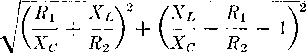 In equation 63 the term Xl/Xc may be written 4:tfLC = f/f/, where 1/(2тг\/LC) = fr, the resonance frequency of the leakage inductance and wdnding capacitance, considered as lumped and without resistance. Also Xl/R2 = Xcf/R2fr- Assign to the ratio Xc/Ri a value В at frequency fr. Then at any frequency /, Xc/Ri = Bfr/f. In the three cases considered at the low frequencies, R2 = Rl, R2 - E2 Ё1 (63a) (63b) In an amplifier with a band of operating frequencies, e.g., the audio band, a well-designed transformer has uniform voltage ratio for a frequency range extending from the frequency at which Xr ceases to exert any appreciable influence, upward to a zone designated as the high-frequency end of the transformer frequency range. 66. High-Frequency Response. The factors that influence the high-frequency response of a transformer are leakage inductance, winding capacitance, source impedance, and load impedance. Hence a new equivalent diagram, Fig. 107(d), is necessary for the high-frequency end. Winding resistances are omitted or combined as in Fig. 107(b). Winding capacitances are shown across the windings. If primary and secondary leakage inductances and capacitances are combined, Хдг is omitted as if it were infinitely large, and is dropped as before, the circuit becomes that shown in Fig. 107(e). is the leakage reactance of both windings, Xc the capacitive reactance of both windings, and 7?2 the load resistance, all referred to the primary side on a 1:1 turns-ratio basis. At any frequency, the equivalent voltage ratio in the circuit of Fig. 107(e) can be found by the ratio of impedances, as for the low-frequency response. The scalar value is 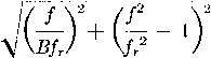 (63c) Equations 63a, b, and с are plotted in Figs. 109, 110, and 111. If Xc/Ri has certain values at frequency fr, the frequency characteristic is relatively flat up to frequencies approaching fr. In particular, performance is good at 5 = 1.0 in all three figures.
0.4 0.6 0.8 1.0 f/fr Fig. 109. Transformer characteristics at high frequencies (line matching). When leakage inductance and winding capacitance are regarded as lumped quantities, current distribution in the windings is assumed to be uniform throughout the range of frequencies considered. As shown in Chapter 7 (Section 97), this assumption is valid up to the resonance frequency Д. At frequencies higher than fr, there may be appreciable error in Figs. 109, 110, and 111. But good frequency characteristics lie mainly below the frequency fr, where the curves are correct within the assumed limits. To use these curves in design work, choose the most desirable 1 ... 12 13 14 15 16 17 18 ... 38 |
|||||||||||||||||||||||||||||||||||||||||||||||||||||||||||||||||||||||||||||||||||||||||||||||||||||||||||||||||||||||||||||||||||||||||||||||||||||||||||||||||||||||||||||||||||||||||||||||||||||||||||||||||||||||||||||||||||||||||||||||||||||||||||||||||||||||||||||||||||||||||||||||||||||||||||||||||||||||||||||||||||||||||||||||||||||||||||||||||||||||||||||||||||||||||||||||||||||||||||||||||||||||||||||||||||||||||||||||||||||||||||||||||||||||||||||||||||||||||||||||||||||||||||||||||||||||||||||||||||||||||||||||||||||||||||||||||||||||||||||||||||||||||||||||||||||||||||||||
|
© 2026 AutoElektrix.ru
Частичное копирование материалов разрешено при условии активной ссылки |