 |
 |
 |
| Главная Журналы Популярное Audi - почему их так назвали? Как появилась марка Bmw? Откуда появился Lexus? Достижения и устремления Mercedes-Benz Первые модели Chevrolet Электромобиль Nissan Leaf |
Главная » Журналы » Transformer elementary form 1 ... 14 15 16 17 18 19 20 ... 38 ELECTRONIC TRANSFORMERS AND CIRCUITS Eh IrR I \ (69) where Ец Ef harmonic voltage ampHtude fundamental voltage amplitude harmonic current amplitude fundamental current amplitude R\R2/{R\ + 2)- Rl, 2, and X.v are as shown in Fig. 107(c).i 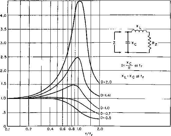 Fig. 120. Step-down transformer impedance at high frequencies. If flux density is below the knee of the saturation curve, and if Xr = 3R2 at the lowest operating frequency, the harmonic amplitude is less than 5 per cent. An air gap in the core reduces this figure. Table XIII gives typical harmonic currents for silicon steel. Output voltage distortion may be analyzed to find harmonic content by the usual Fourier method. Several simplifications have been de- 1 For a discussion of equation 69 and magnetizing currents in general, see Harmonic Distortion in Audio-Frequency Transformers, by N. Partridge, Wireless Engr., 19 (September, October, and November, 1942). Table XIII. Typical Silicon-Steel Magnetizing Cxtrrent Harmonic Components with Zero Impedance Source Btn Percentage of Percentage of Gauss 3rd Harmonic 5th Harmonic 100 4 1 500 7 1.5 1,000 9 2.0 3,000 15 2.5 5,000 20 3.0 10,000 30 5.0 vised to reduce the labor and increase accuracy. In general, if the recommended tube load impedances are maintained, harmonic percentages will be as given in the tube manuals. If other load impedances obtain at some frequencies, to predict the harmonic output requires harmonic analysis. 68. Push-PuU Amplifier Transformers. The analysis of single-side amplifiers in Section 67 applies to class A push-pull, except that the second-harmonic components in the amplifier output are due to unlike tubes rather than to low-impedance distortion. The internal tube resistance of a class В amplifier varies so much with the instantaneous signal voltage on the grids, power output, and plate voltage that it is not practicable to draw curves similar to Figs. 110 and 113 for class В operation. Qualitatively, the characteristic curves may be expected to follow the same general trend as for class A amplifiers. A basis for class В amplifier design is to make the transformer constants such that the load impedance does not fall below a given percentage of the load resistance R2. This is discussed below. Usually the decline with frequency response is greater for class В than for class A amplifiers, because the effect of internal plate impedance is greater. In the extreme, frequency response falls off proportionately with load impedance. A change in mode of operation occurs in a class В amplifier as the output passes from one tube to the other in the region of cut-off. This change-over may cause transient voltages in the amplifier which distort the output voltage wave form. If the two halves of the transformer primary winding are not tightly coupled, primary-to-primary leakage inductance causes nicks in the output voltage wave, in somewhat the same way as leakage inductance in a rectifier plate trans- iFor example, Graphical Harmonic Analysis, by J. A. Hutcheson, Electronics, 9, 16 (January, 1936). former. In a class В amplifier, the change from one tube to the other is less abrupt than in a rectifier, but in triode amplifiers perceptible nicks in the voltage wave occur if the ratio of primary-to-primary leakage reactance to average plate resistance is 4 or more. CORE NO LEAKAGE FLUX IN SPACE BETWEEN COILS 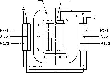  Fig. 121. Core-type push-pull balanced windings. Balanced operation in a push-pull amplifier, i.e., equal plate current and voltage swing on both sides, is possible only if the tubes are alike and if transformer winding turns and resistances per side are equal. Shell-type concentric windings do not fulfill this condition because the half of the primary nearer to the core tongue has lower resistance than the other half. Balance is easier to achieve in the core type of arrangement shown in Fig. 121. In class A amplifiers close primary-primary coupling is not essential, and balance may be attained by arranging part coils as in Fig. 122. Because only half of the primary winding of a class В amplifier carries current during a half-cycle, the leakage flux and therefore the primary-to-secondary leakage inductance have approximately half the values with both windings acti\x all the time. With capacitive currents, both windings are active, at least partially. Transformers with J) > 1.0 have low capacitive currents, low leakage inductance, high resonance frequency, and extended frequency range, in addition to the 1 See Quasi Transients in Class В Audio-Frequency Push-Pull Amplifiers, by A. Pen-Tung Sah, Proc. I.R.E., U, 1522 (November, 1936). 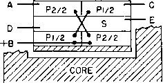 Fig. 122. Shell-type push-pull balanced windings. load-impedance advantages given in Section 67. At high frequencies a class В amplifier transformer presents a circuit to the tubes like that in Fig. 123. Let Li be leakage inductance between the halves of the 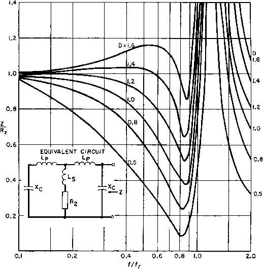 Fig. 123. High-frequency load impedance of class В amplifiers. primary winding, and L2 between each half of the primary and the secondary. Li is the inductance of one half of the primary winding, measured with the other half-primary short-circuited and the secondary open. L2 is the inductance of one half of the primary winding, measured with the other half-primary open and the secondary short-circuited. In Fig. 123, Li = 2Lp and L2 Lp -\- Lg. Resonant frequency fr is determined by Xc and Хы = 27r/Li. In this figure D = Xc/R2 at fr- First one tube delivers power into the equivalent circuit at one end; then, during the next half-cycle, this tube is cut off and the other tube delivers power into the circuit at the other end. Thus the transformer equivalent impedance Z seen looking into the circuit, first at the end shown and then at the other end, is fed by one of the tubes at all times. Impedance ratio Z/R. varies with frequency as in Fig. 123. For some values of parameter D, impedance falls more rapidly than for class A amplifiers (Fig. 119), but frequency jr in Fig. 123 is determined by h and С having approximately half the values of these elements in class A amphfiers. Hence class В impedance stays flat at higher frequencies, although response may droop at lower frequencies, than for class A. Figure 123 is drawn for a ratio of L1/L2 = 1.5, which is a practical design ratio. Lowr ratio L1/L2 results in deeper valleys in the impedance curve; higher L1/L2 is more likely to cause nicks in the voltage wave. Good practice consists in designing class В amplifier transformers so that the highest operating frequency is less than fr/2 and bi/L2 й 1.5. Then harmonic distortion at high frequencies should not exceed 5 per cent. Class В modulation transformer impedance is influenced by circuit elements, so that maintenance of constant impedance over a wide frequency band becomes an overall amplifier problem. This is discussed further in Chapter 6. Capacitive currents also cause unbalance at high frequencies, even with winding arrangements like Figs. 121 and 122. This is evident if the secondary winding in these figures is grounded at one end; the effective capacitances to the two primary windings are then unequal. This problem may be solved by keeping the capacitances small with liberal spacing, but this practice increases leakage inductance and cannot be carried very far. Coil mean turn length should be kept as small as possible by the use of the most suitable core steel. Core-type designs have smaller mean turns than shell-type. Also, the two outer coil sections have low capacitance to each other and to the case if liberal spacing is used, without an increase in leakage inductance. Flux in the space between the outer sections links all the windings on one leg and hence is not leakage flux. Consequently, this space is not part of the term a in equation 33 (p. 76). In push-pull amplifiers the winding arrangement of Fig. 121 is advantageous because of the low capacitance between the points of greatest potential difference, A and C. 69. Plate Current Increase. In a lightly loaded amplifier the frequency characteristic stays flat at high frequencies, even with a droop in load impedance, but the plate current rises in inverse proportion to the impedance. If the plate current can rise enough to maintain constant output voltage, this plate current rise may be objectionable from 1 See The Design of Broad-Band Transformers for Linear Electronic Circuits, by H. W. Lord, Trans. AIEE, 69, 1005. the standpoint of tube heating or plate supply regulation. Values of plate current rise calculated on the basis of constant output for low and high frequencies are shown in Figs. 124 and 125. Many satisfactory audio amplifiers have plate currents which would be excessive at the extremes of the range if high or low notes were amplified continu- О о (Г t 200 а: о 0.4 0.6 0.8 1.0 / R2 Fig. 124. Rise in. plate current due to transformer impedance change at low frequencies. ously. They are not damaged because these tones are of short duration. 70. Pentode Amplifiers. Tetrode tubes have an additional grid between anode and control grid to reduce the grid-to-anode capacitance. This additional grid is known as the screen grid and is operated at a positive potential with a-c bypass to reduce the grid-to-anode capacitance. The chief drawback to this type of tube is that the anode voltage swing is limited to the difference between the anode voltage and screen voltage. This disadvantage is overcome by the addition of a third grid known as the suppressor, which removes this limitation and allows large anode \oltage swings down to the diode line of the tube. Sometimes the third electrode is connected internally to the cathode. Similar characteristics are obtained with the so-called beam tubes, which are tetrodes with special screen-grid spacings. Figure 126 shows 6L6 beam tube plate characteristics, with a typical load line of 2,500 ohms. As a single-side amplifier, such a tube is likely to have large distortion because of the uneven spacing of constant-grid-voltage lines. Distortion is reduced in a push-pull amplifier, especially for cc о Ш о ш I 00 0.2 0.3 0.4 0.6 0.8 1.0 f/fr
Fig. 125. Rise in plate current due to transformer impedance change at high frequencies. high power output. Plate resistance is very high in pentodes and beam tubes, of the order of 10 times the load resistance. Pentodes are essentially constant-current devices. The value of load impedance is thus an indication of the output voltage, at least for low frequencies. Response of a low-frequency transformer-coupled pentode amplifier can be taken from Fig. 118. At high frequencies, leakage inductance of the transformer intervenes between the pentode and its load, so that the primary voltage and secondary or load voltage are not identical. In Fig. 127 the change of output voltage for a constant grid voltage at high frequencies is shown. In this figure, the equivalent circuit is a pi-filter, which is 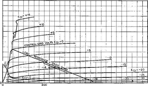 100 - 300 400 PLATE VOLTS Fig. 126. Plate characteristics of type 6L6 beam tube. desirable for pentode transformers, and is approximated when the transformer ratio is 1:1. Harmonic content of pentodes is high, especially in single-side amplifiers. Large phase angle and low load impedance produce undesirable distortion. It is best to use values of Хдт/Дз greater than 2 in Fig. 118 at the lowest frequency to avoid distortion. 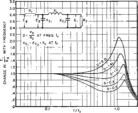 Fig. 127. Pentode frequency response with pi-filter output circuit. Semiconductor amplifiers known as transistors have emitter, collector, and base electrodes; these are analogous, respectively, to grid, plate, and cathode in a vacuum tube. Emitter and collector currents are of the same order of magnitude in grounded-base transistors, but collector impedance is much larger than emitter impedance. To match impedances, transformer coupling is often used between stages of transistor amplifiers. Junction transistors resemble pentode amplifiers in having nearly constant collector current over a large range of collector voltage. Hence junction transistor transformer operation closely resembles that of pentode vacuum-tube transformers, and the foregoing discussion is generally apphcable to both. 71. Calculation of Inductance and Capacitance. Transformer-coupled amplifier performance is dependent at low frequencies upon transformer OCL and at high frequencies upon leakage inductance  where N = turns in winding Ac core area in square inches Ig = total length of air gap in inches Ic = core length in inches M = permeability of core (if there is unbalanced direct current in the winding, this is the incremental permeability). For concentric shell- or core-type windings the total leakage inductance referred to any winding is l{)mMT(2nc -f a) where N = turns in that winding MT = mean length of turn for whole coil a = total winding height b = winding width с = insulation space n = number of insulation spaces = number of primary-secondary interleavings (see Fig. 57, p. 75). Winding capacitance is not expressible in terms of a single formula. The effective value of winding capacitance is almost never measurable, because it depends upon the voltages at the various points of the winding. The capacitance current at any point is equal to the voltage across the capacitance divided by the capacitive reactance. Since many capacitances occur at different voltages, in even the simplest transformer, no one general formula can suffice. The major components of capacitance are from 1. Turn to turn. 2. Layer to layer. 3. Winding to winding. 4. Windin s to core. and winding capacitance. Calculation of these quantities is essential in design and useful in tests for proper operation. Inductance formulas are repeated here for convenience, along with capacitance calculations. 3 2NA OCL =--- (henrys) (38) 1 ... 14 15 16 17 18 19 20 ... 38 |
|||||||||||||||||||||||||||||||||||||||||||||||||||||||||||||||||||||||||||||||||||||||||||||||||||||||||||||||||||||||||||||||||||||||||||||||||||||||||||||||||||||||||||||||||||||||||||||||||||||||||||||||||||||||||||||||||||||||||||||||||||||||||||||||||||||||||||||||||||||||||||||||||||||||||||||||||||||||||||||||||||||||||||||||||||||||||||||||||||||||||||||||||||||||||||||||||||||||||||||||||||||||||||||||||||||||||||||||||||||||||||||||||||||||||||||||||||||||||||||||||||||||||||||||||||||||||||||||||||||||||||||||||||||||||||||||||||||||||||||||||||||||||||||||||||||||||||||
|
© 2026 AutoElektrix.ru
Частичное копирование материалов разрешено при условии активной ссылки |