 |
 |
 |
| Главная Журналы Популярное Audi - почему их так назвали? Как появилась марка Bmw? Откуда появился Lexus? Достижения и устремления Mercedes-Benz Первые модели Chevrolet Электромобиль Nissan Leaf |
Главная » Журналы » Transformer elementary form 1 2 3 4 5 ... 38 12 ELECTRONIC TRANSFORMERS AND CIRCUITS accurate calculation of load voltage with large core exciting current, a point-by-point analysis would be necessary. 8. Flux and Average Voltage. If the variables are separated in equation 1, thus edt= ~N X lO~c?0 an expression for flux may be found : je dt -N X 10- Jdф Now if we consider the time interval 0 to эг/со, we have edt= -NX 10-J = -2Л^Ф^ах X 10- (9) fmax Equation 9 gives the relation between maximum flux and the time integral of voltage. The left side of the equation is the area under the voltage-time wave. For a given frequency, it is proportional to the average voltage value. This is perfectly general and holds true regardless of wave form. If the voltage wave form is alternating, the average value of the time integral over a long period of time is zero. If the voltage wave form is sinusoidal, the flux wave form is also sinusoidal but is displaced 90° as in Fig. 5, and the integral over a half-cycle is -1.41 whence - тг/о) 1.41 X lOJ Фхпах =---- (10) Equation 10 is the relation between maximum flux, effective voltage, frequency, and turns. It is a transposed form of equation 4. 9. Ideal Transformer. The use of equivalent circuits enables an engineer to calculate many transformer problems with comparative ease. It is always necessary to multiply properties in the referred winding by the proper ratio. This has led to the interposition of a transformer of the right turns ratio somewhere in the equivalent circuit, usually across the load. The transformer thus used must introduce no additional losses or voltage drops in the circuit. It is called an ideal transformer, and it has negligibly small winding resistances, leakage flux, core loss, magnetizing current, and winding capacitances. Some powder and audio transformers very nearly approach the ideal transformer at some frequencies. For example, in a typical 50-kva plate transformer, the winding resistance IR drops total 1 per cent and the leakage reactance IX drops 3 per cent of rated voltage, the core loss 0.6 per cent of output power and magnetizing current 2 per cent of rated primary current. When the term ideal transformer is used, it should be borne in mind that negligibly small is not zero. Particularly in electronic work, where frequency may vary, a limiting frequency may be reached at which the transformer is no longer ideal. Moreover, even if the limiting frequency is very low, it is never zero. There must be voltage variation if transformation is to take place. The assumptions of equations 5 to 7 were the same as for an ideal transformer. 10. Polarity. Let turns from equation 2a be substituted in equation 5. Then we have NJr = N2I2 (11) or the primary and secondary ampere-turns are equal and opposite. This equality holds for only the load component of /1; that is, exciting current has been regarded as negligibly small. If there is a direct current in the load, but not in the primary, or vice versa, equation 11 is true for only the a-c components. A 1:1 turns-ratio transformer is shown diagramatically in Fig. 7. Impressed voltage is Ei, and primary current is It- Induced voltage Ei is slightly less than Ei, and is the same in magnitude and direction for both windings. Secondary current I2 flows in the opposite direction to /1. Instantaneous polarities are indicated by -j- and - signs. That is, when El reaches positive maximum so do Ei and E2. Dots are conventionally used to indicate terminals of the same polarity; dots in the circuit symbol at the right of Fig. 7 are used to indicate the same winding directions as in the left-hand figure. 11. Regulation, Efficiency, and Power Factor. Transformer regulation is the difference in the secondary terminal voltage at full load and at no load, expressed as a percentage of the full-load voltage. For the resistive load of Fig. 3(a), (6), and (c), {Eg -El) Per cent regulation = 100 -~- (12) 1 See Magnetic Circuits and Transformers, M.I.T. Electrical Engineering Staff, John Wiley & Sons, New York, 1943, p. 269. pr i. I SEC. CORE pri. SEC. о Fig. 7. Transformer polarity. Since with low values of leakage reactance Eg ~ El = IR, Per cent regulation = ШШ/Еь (13) provided that R includes the primary winding resistance multiplied by the factor {N2/N1Y as well as the secondary winding resistance. If leakage reactance is not negligibly small, approximately Per cent regulation = 100 Efficiency is the ratio IR 1  2-л l/ J Output power Output power plus losses (14) (15) where losses include both core and winding losses. A convenient way of expressing power factor is Ролуег factor = Output power plus losses (16) Input volt-amperes Equation 16 gives the power factor of a transformer plus its load. One of the problems of transformer design is the proper choice of induction to obtain low values of exciting current and high power factor. Low power factor may cause excessive primary winding copper loss, low efficiency, and overheating. 12. Wave Shapes. Transformers in electronic circuits may be subjected to alternating and direct currents simultaneously, to modified sine waves, or to other non-sinusoidal waves. Although there is a relation between current and voltage wave shapes in a transformer, the two are frequently not the same, as has already been seen in Fig. -CORE FLUX -rms dt (17) where i = current at any instant / = frequency of repetition of current waves per second T = duration of current waves in seconds t = time in seconds. Average current values are h=ff г dt (18) In the first wave shape, T = 1/f. In the fifth wave shape, Г 28 is the current wave duration. 5. D-c components of primary voltage are not transformed; only the varying a-c component is transformed. Secondary current may be determined by the connection of the load. For example: if the load is a rectifier, the current will be some form of rectified wave; if the load is a modulator, the secondary current may be the superposition of two waves. If the primary voltage is non-sinusoidal, then the secondary current almost certainly will be non-sinusoidal. If the primary voltage comes from an alternating source only, and the load is a half-wave rectifier, the secondary current has a d-c component, but the primary current has no d-c component except under changing conditions. That is to say, in the steady state there is no primary d-c component resulting from secondary d-c component alone. This is true, because any direct current in the primary requires a d-c source. But by the initial assumption there is no direct current present in the primary. Under these conditions, the core flux may be very much distorted because the flux excursions go into saturation in one direction only. In succeeding chapters, two values of current will be of interest in circuits with non-sinusoidal waves, the average and the rms. Average current causes core saturation unless there is an air gap. Rms current determines the heating of the windings and is limited by the permissible temperature rise. Voltage wave form will be dealt with in subsequent chapters. Common current wave forms are tabulated here for convenience. (See Table I.) Root-mean-square or rms current values are based upon the equation Current Wave Shape 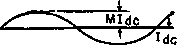
!£7A Ш Description Direct current with superposed sine wave Half-sine loops of T duration and / repetition rate Square waves of T duration and / repetition frequency Sawtooth wave of T duration and / repetition frequency Trapezoidal wave of / repetition fre-quencjr rras 2lpkfT IpkJT IpkfT Ipklib + T) In both equations 17 and 18, T refers to a full period. This is in contrast to steady-state sinusoidal alternating currents, the rms and average values of which are developed over a half-period because of the symmetry of such currents about the zero axis. Table I. Non-Sinusoidal Cubrent Wavk Fokms 2. TRANSFORMER CONSTRUCTION, MATERIALS, AND RATINGS 13. Construction. Most electronic transformers are small, and for small transformers the shell-type core is usually most suitable because only one coil is required. Figure 8 shows shell-type transformer assemblies.     Fig. 8. Transformers with shell-type core. The magnetic path is divided, half the flux enclosing one side of the coil and half the other. The coil opening is called the window. Between the windows is the core tongue, which is twice as wide as the 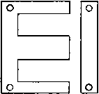  о -----1 I ,J Fig. 9. Shell-type laminations. -window tongue iron around the rest of the window. The core is built up of thin laminations to reduce eddy-current losses; typical shapes are shown in Fig. 9. Iternate stacking of the lamination pairs may be used to reduce magnetic reluctance and keep magnetizing current small. To reduce assembly cost, this alternate stacking is sometimes done in groups of 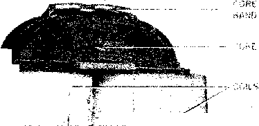 - ................................................ 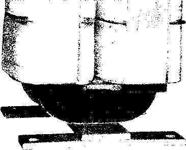 Fig. 10. Core-type transformer. two or more laminations, with some increase in magnetizing current. A wide range of sizes of shell-type laminations is available. At 60 cycles, common thicknesses are 0.014 in., 0.019 in., and 0.025 in. Shell-type laminations are made with proportions to suit the transformer. In the E-I shape a scrapless lamination is widely used. Two Es facing each other are first punched, and the punched-out strips are of the right dimensions to form two Is. Then the Es are cut apart. This economy of material is not justified in transformers in which turns per layer, and hence window width, must be reduced relative to window height. For some applications, the core-type transformer is preferable. In these there is only one magnetic path, but there are two coils, one on each leg of the core. A core-type transformer is shown in Fig. 10, and some core-type laminations in Fig. 11. Cores wound from continuous steel strip are widely used. One common shape is illustrated in Fig. 12; it is known as the type С core. Steel strip is first wound to the proper build-up on a mandrel. The и -I L Fig. 11. Core-type laminations. 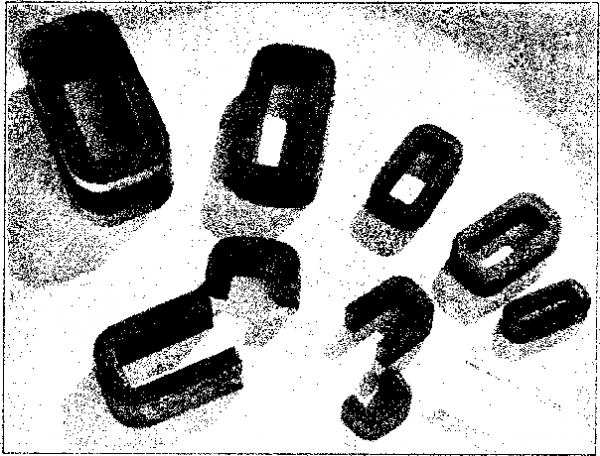 Fig. 12. Type С cores. wound core is then annealed, impregnated with a bond, and cut in two to permit assembly with the coil. After assembly with the coil, the core is held together with a steel band as in Fig. 10. Several advantages accrue from this construction, which will be discussed in Section 15. Typical assemblies using two type С cores are shown in Figs. 13 and 14; they correspond to shell-type laminations. Because it is simpler to assemble a single-core loop, a single core is often used, especially in small sizes. See Fig. 15. In 60-cycle service the laminations are usually stacked alternately to produce an overlapping joint. This is approximated in the type С cores with ground gap surfaces which fit closely together. Either type of core can be used with core gaps; laminations are stacked butting, with no overlap. The desired amount of gap material, such as fish-paper, is inserted between the gap surfaces. 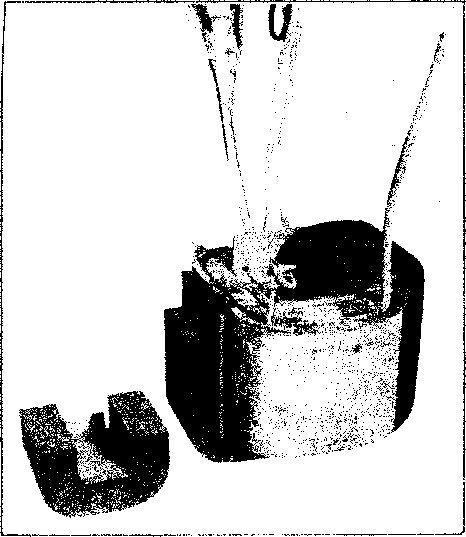 Fig. 13. Partly assembled transformer. 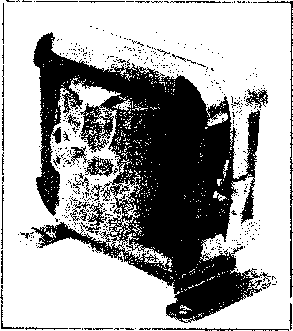 Fig. 14. Assembled type С cores and coil.  Fig. 15. Single-coil, single-core assemblies. 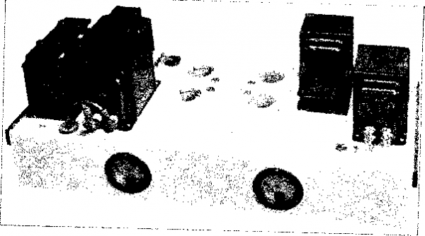 Fig. 16. Transformers mounted on amplifier chassis. 1 2 3 4 5 ... 38 |
|
© 2026 AutoElektrix.ru
Частичное копирование материалов разрешено при условии активной ссылки |