 |
 |
 |
| Главная Журналы Популярное Audi - почему их так назвали? Как появилась марка Bmw? Откуда появился Lexus? Достижения и устремления Mercedes-Benz Первые модели Chevrolet Электромобиль Nissan Leaf |
Главная » Журналы » Transformer elementary form 1 ... 18 19 20 21 22 23 24 ... 38 sary to keep the inductance down to a value determined by the tank circuit Q or volt-amperes. This in turn is dictated by the required harmonic content. The use and selection of core materials are approximately the same as those indicated in Sections 78 and 79. Class С oscillators are less desirable for very low harmonic requirements, because of the difficulty of designing tank circuits with sufficiently high Q. Where large harmonic values can be tolerated, the transformer can be designed for low Q, but the wave form becomes поп- 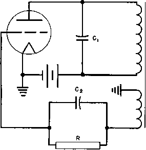 то OUTPUT CIRCUIT Fig. 152. Transformer-coupled audio oscillator. sinusoidal. Transformer grid circuit turns are large, approximately the same as plate turns, and the grid voltage would be high if grid current did not limit the positive voltage swing. During the half-cycle when the tube is operating, the voltage wave has a roughly rectangular shape, and during the rest of the cycle it peaks sharply to a high amplitude in the opposite direction. Core losses are difficult to predict because loss data are not normally available for such wave forms. Consequently, designs of this type are usually cut-and-try. The frequency of oscillation varies with changes in load; hence low Q class С oscillators are to be avoided if good frequency stability is required. 83. Shielding. Gain of 80 to 100 db is often reached in high-gain amplifiers. It is important in these amplifiers that only the signal be amplified. Small amounts of extraneous voltage introduced at the amplifier input may spoil the quality or even make the received signal unintelligible. One source of extraneous voltage or hum is in stray magnetic fields emanating from power transformers in or near the amplifier. The stray fields enter the magnetic cores of in ut trans- formers and induce small voltages in the windings, which may be amplified to objectionably high values by the amplifier. Several devices are used to reduce this hum pick-up: 1. The input transformer is located away from the power transformer. 2. The coil is oriented for minimum pick-up. 3. Magnetic shielding is employed. 4. Core-type construction is used. The first expedient is limited by the space available for the amplifier, but, since the field varies as the inverse cube of the distance from the 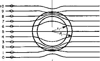 Fig. 153. Refraction of magnetic field by iron shield. source, it is obviously helpful to locate the input transformer as far away from the power transformer as possible. The second method is to orient the coil so that its axis is perpendicular to the field. It requires extra care in testing. Magnetic shielding is the brute force method of keeping out stray fields; core-type construction is effective and does not materially increase the size. Of course, any of these methods increases manufacturing difficulties to a certain extent. Magnetic shielding is ordinarily accomplished by a thick wall of ferrous metal or a series of thin, nesting boxes of high permeability material encasing the windings and core of the input transformer. Neither type of shield is applied to the power transformer because the fiux lines originate at the power transformer and fan out in all directions from it. A large percentage of the fiux would strike the shield at right angles and pass through it. On the other hand, the stray field near the input transformer is relatively uniform, and very few fiux lines strike the shield at right angles. Thus more fiux is bypassed by it. The action of a thick shield in keeping stray flux out of its interior is roughly illustrated in Fig. 153. FIN. FIN. Fig. 154. Flux directions in a core-type transformer. Multiple shields increase the action just mentioned because eddy currents induced in the shields set up fluxes opposing the stray field. Sometimes alternate layers of copper and magnetic material are used for this purpose, when hum pick-up 50 or 60 db below the no-shield value is required. In core-type transformers the flux normally is in opposite directions in the two core legs, as shown in Fig. 154. A uniform external field, however, travels in the same direction in both legs, and induced voltages caused by it cancel each other in the two coils. The relative effectiveness of these expedients is shown in Fig. 155. Hum pick-up is given in decibels with zero decibel equal to 1.7 volts across 500 ohms, and distance from a typical small power transformer as abscissas. All curves are for 500-ohm windings working into their proper impedances, and with no orientation for minimizing hum. Using impedances much less than 500 ohms reduces the hum picked up. Orientation of coil position also reduces hum. For all types of units there is a position of minimum hum. With the unshielded shell type the angle between the transformer coil and the field is almost 90° and is extremely critical. With shielding, this angle is less critical, but the minimum amount of hum picked up in this position is not noticeably reduced. The core type is less critical, especially with a shield. The minimum amount of hum picked up is from 10 to 20 db less than the shielded shell type in its minimum position. Removing the shields from the core type may change its position of minimum pick-up. This is because the shields reduce hum by a process different from that of the two bucking coils. It is advantageous to have power transformers of the core type. Leakage fiuxes from like coils on the two legs approximately cancel at a distant point. The U-and-I shape of lamination is better than the L shape because of its symmetry. A type С core has the advantage that gaps are inside the coils. Thus fringing is reduced, and stray flux from the core gap is minimized. Static shielding does not prevent normal voltage on a primary winding from being transferred inductively into a secondary winding. It is 1 See S. L. Gokhale, J. AIEE, 48, 770 (October, 1929); also, Magnetic Shielding of Transformers at Audio Frequencies, by W. G. Gustafson, Bell System Tech. J., 17, 416 (July, 1938). effective only against voltage transfer by interwinding capacitance. High-frequency currents from vacuum tube circuits are thus prevented from flowing back into the 60-cycle power circuits via filament and DISTANCE FROM HUM SOURCE-INCHES 5 6 8 10 20 30 50 (0 -45 s о -50 о 0 -55 л n -60 О о: -65 о < CD -70 о Z -75 -80 1 -90 I -100 -105 -МО -115 -120 -125 -130 -135
Fig. 155. Hum pick-up in input transformers. plate transformers. Without shielding, such currents may interfere with operation of nearby receivers. Likewise, voltages to ground on telephone lines are kept from interfering with normal voice frequency voltages between lines. The extent of static shielding depends upon the amount of discrimination required. Usually a single, thin, grounded strip of metal between windings is sufficient, with ends insulated to prevent a short circuit. Magnetic flux in the interwinding space causes eddy currents to flow in such shields, and even shields with insulated ends indicate a partial short circuit on test. This effect reduces the OCL of the transformer. If volts per layer are small compared to total winding voltage, a layer of wire is an effective shield. INVERTED HYBRID (□) NO RESPONSE IN R4 FROM Eq. response IN RgSRs (C) RESPONSE IN RgaR, BUT NOT IN RFROM £3 3 Ез У R, 2 3 ЕЗ (b) RESPONSE IN R I, Rg.a R4 - FROM E3 (d) EQUIVALENT CIRCUIT, т R4 REPRESENTS SECONDARY LOAD Fig. 156. Hybrid coil operation. The start turn is grounded and the finish left free, or vice versa. A wire shield has none of the short-circuit effect of a wide strip shield. Usually a transformer that requires static shielding has a low-voltage winding; the shield can be placed close to this winding, needs little additional insulation, and occupies but a small fraction of the total coil space. If shields are placed between high-voltage windings, as in modulation transformers, the shields must be insulated from each winding with thick insulation. This materially increases the coil mean turn length, transformer size, and difficulty in obtaining good high-frequency response. Shields have questionable value in such transformers and usually are omitted. 84. Hybrid Coils. Hybrid coils are used to isolate an unwanted signal from certain parts of a circuit, and allow the signal to be used in other parts of the circuit. In the hybrid coil shown in Fig. 156(a) the lower windings or primary sections are balanced with res ect to each other, and the two resistors R2 and R3 are equal. Voltage Eq applied between the primary center tap and ground causes equal currents to flow in opposite directions through the two halves of the primary winding, and therefore produces zero voltage in the secondary winding. By this means, signal Eq arrives at resistors R2 and R3 undiminished, but there is no voltage in R4, connected across the secondary coil. Figure 156(b) shows what happens in this circuit if the voltage is applied across R3 instead of across Ri. In this case, the voltage E appears across resistors Ri, R2, and R, that is, in all parts of the circuit. An inverted hybrid coil is shown in Fig. 156(c). Here voltage Eg is applied across the upper coil, which is now the primary. The secondary sections are assumed to be balanced. Therefore, there is zero voltage between the center point of the secondary winding and ground, and though a signal appears at R2 or R there is no signal across Ri. Thus a hybrid coil works in both directions. It has been assumed that R2 and R3 are equal and that the two primary half-windings are of equal number of turns. This is not necessarily true, for, if the resistance of R2 is twice that of Rs, the number of turns connected to R2 should be twice those connected to Rs. However, it is important that, through the range of frequency in which the hybrid coil is desired to function, the balance between the two halves be maintained closely. The most exact balance is achieved for R2 = Rs by winding the two halves simultaneously with two different wires. This method gives good isolation of the undesired signal. Other methods introduce some ratio error which reduces the isolation. For the same reason, it is necessary to balance the circuit with regard to capacitance and leakage inductance. That is, if a capacitance exists across Rs, such as line capacitance for example, an additional equivalent amount should be added across R2 in order to achieve the balance desired. Likewise, any inductive apparatus, adding either series or parallel inductance in one circuit, should be compensated for by inductance of like character in the other circuit. Adding series inductance, for example, in series with Rs will not compensate for shunt inductance across R2, or vice versa, as the two have opposite effects with regard to frequency and therefore balance is attained only at one frequency. Assume a perfect transformer having no exciting current and no leakage inductance between the two halves, and a transformer with equal turns in the two halves of the primary winding. Assume currents in the directions shown in Fig. 156(d). Then Jl = /2 + /3 (88) Ег = I2R2 + hRi (89) Es = hRi + E2 (90) On the assumption of equal turns in the two half-windings, Ei - E2. If the magnetizing current is assumed to be zero, the ampere-turns and hence the volt-amperes in the two primary halves are equal. The secondary load can be considered as reflected into the primary winding as resistor h = {E, -h E2)/Ri (91) (/3 - h)E2 = (/2 + h)Ei (92) If equations 88 to 92 are combined, an expression for Z3 can be found: E + 4ЙА + ад Z3 = - = -- (9d) 7з 4Й1 + 4Й2 + й4 If the secondary circuit is open, = 00, and equation 93 becomes 3 = 41 -h R2 (94) 85. Amplifier Tests. Tests for hum, distortion, linearity, and frequency response can be made with meters in the output circuit when voltage of a known frequency and wave form is applied to the input. Hum and distortion are conveniently measured by instruments specially made for the purpose. Linearity is measured by varying the input voltage and measuring corresponding output voltage. Frequency response is measured at a fixed input or output voltage, but frequency is varied. Normal production testing of amplifiers requires no more than such overall tests. But, in the development of the amplifier, excessive hum, distortion, or other defects may be indicated, and tests must be applied stage by stage to locate the trouble. Voltage is usually measured by a tube voltmeter, one terminal of which is grounded. In a push-pull amplifier, it is therefore necessary to block the direct voltage and measure the alternating voltage on each side, A cathode-ray oscilloscope is helpful in checking phase shift and wave form at various points. Before being assembled in the amplifier, transformers are tested for turns ratio, balance, polarity, OCL, winding resistance, core loss, and insulation strength. Although with new designs it is desirable to check leakage inductance, winding capacitance, and shielding, these properties vary less in a given design than the others. Methods for making most of these tests are the same as those described in Chapter 3. Tests for capacitance are limited to winding-to-winding and winding-to-core capacitance. These tests are made on a capacitance bridge. Evaluation of capacitance measurements is made as in Section 71. Balance (an important property of push-pull amplifiers) and shielding tests are described in Standard TR-121 of the Radio-Electronics-Television Manufacturers Association. Reactor Q is measured either on an inductance bridge (which also measures a-c resistance as in Fig. 75) or on a special Q meter. In either method, rated voltage and frequency should be used. Modulation reactors are usually measured for inductance with full direct current in the winding; great care should be exercised to prevent sudden interruption of this current and consequent dangerous high voltage. Such reactors are often surge-tested to guard against breakdown in service under conditions of overmodulation. In the diagram of Fig. 157, the first two stages have current feedback, and so initial tests were made with the circuit shown. But overall voltage feedback from the modulator plates back to the 6J7 grids was not applied until the amplifier was first tested without it. Then resistors from which feedback is derived were adjusted to produce the feedback voltage necessary to give the required performance. The carrier power amplifier was completely adjusted before modulation was applied. Percentage of modulation was measured by the increase of carrier output current when modulation was applied. Inductance RFC and capacitor Ci maintain the modulator load constant at high frequencies. C2 in this circuit is the audio coupling capacitor. Separate meters are provided to measure the plate current of each driver and modulator tube, so that bias may be adjusted for the same plate current on each side. Proper operation is predicated on amplifier stability, which often is not obtained when power is first turned on. Local or parasitic oscillations may easily occur as a result of natural resonance of circuit elements or even in connections and tube electrodes. These must be detected and eliminated by corrective measures which apply to the trouble. Some of these troubles may be caused by long leads, especially in the grid circuit. Tubes may require resistors in the plate and grid leads to damp out parasitic oscillations. Resistors are used in this manner in the amplifier shown in Fig. 157. Coils in circuits with widely different voltages should not be coupled closely, because regeneration may result. In circuits with high voltage, and therefore large capacitive currents, it may be necessary to add shielding to то PA TANK COIL 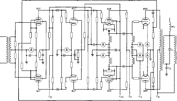 Fig. 157. Amplifier schematic diagram. prevent stray pick-up from one stage to another. In push-pull amplifiers, if some circuit element is unbalanced, it may give rise to a push-push oscillation which can be eliminated by better balance, or by decoupling the tube plates at the unwanted frequency. If insufficient bypass capacity is used on plate or bias supplies, interstage coupling may occur at low frequencies. The frequency may be less than 1 cycle per second. This kind of instability is known as motor-boating. Operating tubes so that some electrode becomes a negative resistance during a portion of the cycle may give rise to oscillations which cannot be prevented except by avoidance of the cause, or by some power-absorbing circuit луЬ1сЬ does not affect normal operation. The elimination of such trouble requires much testing time and skill, but it must be done before performance tests are made. 86. Design Examples. Example (a). Transformer for Pi-Filter Modulator. Frequency range 100 to 5,000 cycles. Audio output 400 watts. Power amplifier Eb/Ib = 10,000 ohms. Voltage ratio primary/secondary (1,180 -f- l,180)/2,000. /i = 60 cycles. Core: 4-in. stack of siHcon-steel lamination B, Fig. 44 (p. 55). Turns primary/secondary (800 -f- 800)/l,380 No. 26 wire. Ac = 7.2 sq in. net; 8.0 sq in. gross. Ic = 12.75 in. k = 0.012 in. Possible tube current unbalance = 0.032 amp. 0.6 X 800 X 0.032 Bdc =-- = 1,260 gauss. 3.49 X 2,000 X 106 - 100 X 7.2 X 1,380 = - Вт = 8,260 gauss. From Fig. 70 (p. 98), ju = 9,000+ 3.2 X (1,380)2 X 8 X 10-8 Secondary OCL = Q.012 + (12.75/9,000) = Xl at /1 = 6.28 X 60 X 36.5 = 13,800 ohms. = 115 per cent R at 100 cycles from Fig. 146. Winding arrangement as in Fig. 158, to reduce layer voltage and capacitance. Winding resistances: Total primary 90 ohms. Secondary 80 ohms. Secondary leakage inductance = 53 millihenrys. Capacitances (referred to secondary): 1 ... 18 19 20 21 22 23 24 ... 38 |
|||||||||||||||||||||||||||||||||||||||||||||||||||||||||||||||||||||||||||||||||||||||||||||||||||||||||||||||||||||||||||||||||||||||||||||||||||||||||||||||||||||||||||||||||||||||||||||||||||||||||||||||||||||||||||||||||||||||||||||||||||||||||||||||||||||||||||||||||||||||||||||||||||||||||||||||||||||||||||||||||||||||||||||||||||||||||||||||||||||||||||||||||||||||||||||||||||||||||||||||||||||||||||||||||||||||||||||||||||||||||||||||||||||||||||||||||||||||||||||||||||||||||||||||||||||||||||||||||||||||||||||||||||||||||||||||||||||||||||||||||||||||||||||||||||||||||||||||||
|
© 2026 AutoElektrix.ru
Частичное копирование материалов разрешено при условии активной ссылки |