 |
 |
 |
| Главная Журналы Популярное Audi - почему их так назвали? Как появилась марка Bmw? Откуда появился Lexus? Достижения и устремления Mercedes-Benz Первые модели Chevrolet Электромобиль Nissan Leaf |
Главная » Журналы » Transformer elementary form 1 ... 19 20 21 22 23 24 25 ... 38 Pi - Si(at A) Pi - S2{Sit B) P2 - Siisit C) Pi - S2{aX D) Secondary layer to layer Primary layer to layer Stray and tube Power amplifier r-f bypass 292 iujuf 0 112 58 140 170 50 500 Total = 1,322 jLi/if TO PLATE TO MOD, COUPLING CAPACITOR- TO PLATE
TO Eb COIL FORM- Fig. 158. Section of transformer coil wound for low layer voltage. At high audio frequencies fr = 19,000, D = 0.6, and Z/R2 from Fig. 119 (p, 159) is 87 per cent at 5,000 cycles. Example (&). Audio Oscillator. Ckcuit of Fig. 152, with 6C5 tube, Ев = 150 volts, Ec = -10 volts. Frequency 800 cycles. Plate load impedance = 20,000 ohms. Class В operation; grid swings to +2 volts. Aeg = -12 volts Aep = 150 - 35 = 115 volts Дг = 5.6 ma during positive half-cycle. Average power output = (115 X 5.6)/4 = 160 mw. Transformer voltage ratio P/G = 115/12 = 81/8.5 rms. For low harmonic distortion, volt-amperes = 10 X tube output =1.6 v-a. (115 X 0.707) 1.6 6.28 X 800 X 4 140 = 4,140 ohms. = 0.048 fxt Current in plate winding = 440 - - amp. Core is the same as in Example (6), Section 72. Primary 2,100 turns No. 32 enamel. Winding resistance = 125 ohms. Grid 250 turns No. 42 enamel. Winding resistance = 180 ohms. Ig = 0.060 in., Ic = 4.5 in., Ac = 0.32 sq in., core weight = 0.4 lb. 0.6 X 2,100 X 0.0056 =-0.060 X X Д 3.49 X 81 X 10 = 800 X 0.32 X 2,100 = Вт = 560 gauss. (From Fig. 70, = 2,000.) nnr 3.2 X (2,100) X 0.36 X lO , Pnmary OCL = Q.oeo + (4.5/2,000)- = From Fig. 140 core loss = 0.2 X 0.6 X 0.4 = 0.048 watt. Gap loss = 0.030 watt. Primary copper loss = (0.02) X 125 = 0.05 watt. This leaves 32 mw available for secondary output. Example (c). Cathode Follower. Assume that tubes 828 and 849 in Fig. 157 operate at Ев = 1,700 volts. With Ec= -75 and 700 watts output, 849 plate swing is 1,200, min = 500, peak grid voltage = 4-105, and peak grid current is 0.090 amp. This is peak load for the 828 tube which can operate class ABl. The 828 tube plate swing is 1,200 + 180 = 1,380, or in = 1,700 - 1,380 = 320 volts, and the 828 peak load is 105/0.090 = 1,170 ohms. The cathode choke of 828 and the grid chokes and capacitors of 849 should have 1.41 X 1,170 = 1,650 ohms reactance for 100 per cent modulation at frequency /1. At 10 cycles this would be 27 henrys. Peak voltage across these chokes is the 828 plate swing. 7. HIGHER-FREQUENCY TRANSFORMERS In Chapter 6 the influence of low-frequency performance on size was mentioned. If high transformer OCL is required to maintain good low-frequency response, many turns or a large core are necessary, either of which limits the high-frequency response. But if the amplifier frequency range is wholly composed of high frequencies, this limitation is in large part removed. For example, in a power-line carrier amplifier, the frequency range is 40 to 200 kc. It is then only necessary that OCL be high enough to effect good response at 40 kc. This is a great help in designing for proper response at 200 kc, and makes possible the use of laminated iron-core transformers for these and higher frequencies. 87. Iron-Core Transformers. At power-line carrier frequencies, the principles discussed in preceding sections for lower-frequency transformers apply. In terms of the mean frequency, the band is narrow, 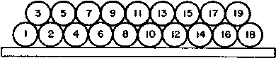 Fig. 159. Two-layer bank winding. but at 40 kc the curves for low-frequency operation portray amplifier performance just as they do at 30 cycles. Likewise at 200 kc care must be used that the limiting factors of leakage inductance and winding capacitance do not interfere with proper operation. In carrier frequency transmitters, transformers are normally used for coupling between stages and for coupling the output stage to the line. They sometimes transform a large amount of carrier power. Coils are usually wound in single layers, spaced well apart to reduce capacitance, and have but few turns. If the necessary turns cannot be wound in a single layer, a bank winding like that shown in Fig. 159 may be used. This winding has more capacitance than a single layer but much less than two layers wound in the ordinary way. Since intrawinding layer-to-layer capacitance is zero in these transformers, the resonance frequency jr is usually determined by winding-to-winding capacitance. In high impedance circuits, the winding-to-winding capacitance may be reduced by winding pies or self-supporting vertical sections side by side. Pies are wound with one or more throws per turn and may be several turns wide. They have the general appearance of Fig. 160. High, narrow core windows or several pies are desirable to re- COIL FORM 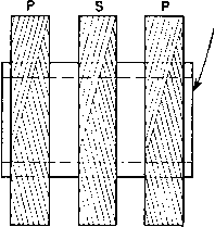 Fig. 160. Pie-section wiadings. duce leakage inductance. Transformer loss is mostly core loss. Two-mil grain-oriented steel can be used advantageously in such transformers, because of its low losses and high permeability. In transmitter operation, class AB or class В amplifiers are commonly used, with or without modulation, which may be as high as 100 per cent. In a receiver, input and interstage transformers also are employed, mainly to obtain voltage gain or for isolation purposes. Similar transformers are used for line matching, especially where overhead lines are connected to underground cables. Line impedance changes abruptly, and transformers may be necessary for good power transfer. Core data at these frequencies are usually not available except for a limited choice of materials and gages. Approximate loss for 2-mil oriented steel is given in Fig. 161. Interpolation or extrapolation from known data may be necessary to estimate core losses. In spite of this limitation, carrier frequency transformers are widely used. Some of the transformers in Fig. 16 operate in the carrier band. Core steel permeability decreases at high frequencies, depending on the 1 See Theory and Design of Progressive and Ordinary Universal Windings, by Myron Kantor, Proc. I.R.E., December, 1947, p. 1563. 100Л 10.0 - 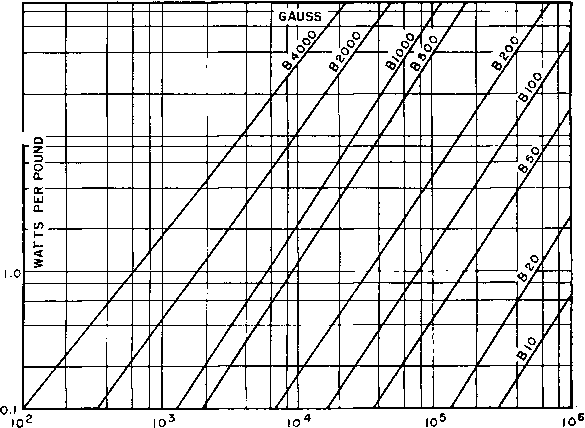 FREQUENCY -CYCLES PER SECOND Fig. 161. Approximate loss for 2-mil steel at higher frequencies. Transformers are used at still higher frequencies. Capacitance limits the upper frequency at which amplifier transformers may be operated. In a tuned circuit amplifier, the tuning includes the incidental and tube capacitance as well as the tank circuit capacitance. A transformer has no tuning to compensate for such capacitances. Even with zero winding capacitance there would be a frequency limit at which any tube could operate into an untuned transformer without 1 For additional core-loss and permeability data at higher frequencies, see The Variation of the Magnetic Properties of Ferromagnetic Laminae with Frequency, by C. Dannatt, J.I.E.E., 79, 667 (December, 1936). lamination thickness. Oriented steel and nickel alloys have high permeability at low frequencies, but, unless thin laminations are used, this advantage disappears at frequencies of 20 to 50 kc. The approximate decline for low induction is showm in Fig. 162. Decrease of permeability may be so rapid that OCL nearly decreases inversely as frequency with 0.014-in. and even 0.005-in. material. Grain-oriented steel 0.002 in. thick is well suited to these frequencies. 3500 3000 2500 2000 < a: I 500 UJ Q. tooo 10 3
10 I05 FREQUENCY-CYCLES PER SECOND Fig. 162. Approximate permeabilities of core steels at higher frequencies. spoiling its efficiency or other characteristics. The most favorable condition for the use of transformers at higher frequencies is low circuit impedance. With low leakage inductance and low impedance circuits, transformer operation is possible in the high- and very-high-frequency bands. 88. Other Core Materials. In the high radio-frequency bands, ferrite cores have the advantage of high resistivity and practically no eddy-current component of core loss. Several grades are manufactured commercially, usually mixtures of manganese, nickel, and zinc ferrites. Figure 163 is a set of normal permeability curves for different grades of ferrites, and Fig. 164 gives initial permeability. Usually the lower-permeability materials have lower loss at higher frequencies, so that permeability is an inverse indication of the relative frequencies at which ferrites are useful. 0.04 0.06 0.08 PERMEABILITY О^Ср / 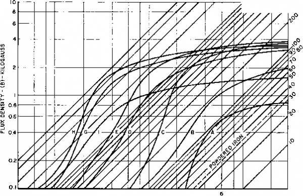 0.4 0.6 0.8 1.0 2 4 MAGNETIZING FORCE (H)-OERSTEDS 8 10 20 30 Fig. 163. Magnetic ferrite normal permeability. 10,000 о :iooo < ш § 100
FREQUENCY, MEGACYCLES Fig. 164. Magnetic ferrite initial permeability. Л о: о OJOOOOl
FREQUENCY, MEGACYCLES Fig. 165. Loss factor of ferrite cores, Losses in ferrites are often related to the product /xoQ. (See Fig. 165.) This relation is approximately as follows: Core loss 0.41 X IQ-fB (95) Instead of noQ, the quantity Rser/iJfL is sometimes plotted, where Rsev is the equivalent series resistance corresponding to core loss. Equation 95 then becomes Core loss = 0.065 X IQ-fB (96) SECONDARY COIL PRIMARY COIL CORE XXXf-------1НИ- TXXi-------1 HI At the lower radio frequencies, finely divided powdered iron has loss lower than some ferrites. Owens gives 1.0 mc as the highest frequency for which this holds. Both ferrites and powdered iron have temperature limits far below that of strip-wound cores: ferrites because of low Curie temperature, and powdered iron because of possible damage to the bonding material. Powdered iron with certain bonds has the better temperature coefEcient of permeability. Both materials are available in the forms shown in Fig. 144. 89. Capacitance Evaluation. In high-frequency transformers, the capacitances differ from those in audio transformers in that the windings are usually single layers, whose tum-to-turn capacitance is negligible compared to capacitance between windings and to the core. For example, in the transformer in Fig. 166, the primary and secondary are each wound in a single layer concentrically, in the same rotational direction, and in the same traverse direction (right to left). It will be assumed that the right ends of both windings are connected to ground (or core) through large capacitances, as shown dotted, so that the right ends are at substantially the same a-c potential. Primary capacitance Ci is composed of many small incremental capacitances Cp, and secondary C2 of many small incremental capacitances Cs, each of which has a different voltage across it. Likewise, 1 See Analysis of Measurements on Magnetic Ferrites, by C. D. Owens, Proc. I.R.E., 4U 360 (March 1953). vi sX -i ч!/ vL ~i--1--Г- FiG. 166. Single-layer windings. Ci = - SCp and Сз = - 3 3L Ns If the transformer is step-down, (97) {Np - Ns) Cp + XCa and Cs = - Cs (98) 3 3L Np If the ratio is 1:1, Ns = Np, Ci = iCp and C2 = iC, (99) For transformers with opposite angular rotations of primary and secondary windings, or with opposite traverse directions (but not both), minus signs in the factors {Np - Ns)/Np and (Л^ - Np)/NJ in equations 97 and 98 become positive; there is no other change. For transformers with both angular rotations and traverse directions opposite there is no change at all in these equations. If there is a shield between primary and secondary, omit terms containing Ca in these equations, and make %Cs and Cp include the capacitance of secondary and primary to shield, respectively. is the measurable capacitance of the short-circuited secondary to core, and %Cp that of the short-circuited primary to core. In push-pull amplifier transformers, the secondary winding is interleaved between two primary halves. The rotational directions of winding and traverse are important, as they affect not only effective capacitance but also plate-to-plate coupling. It is usually best to have all windings with the same rotational direction and traverse, and to connect the primary halves externally. Winding resistance increases with frequency because of eddy currents in the larger wire sizes, and copper loss increases proportionately. Formulas for single-layer coils are given in handbooks. Eddy-current resistance of layer-wound coils in deep open slots is plotted in Fig. 167 as a function of conductor thickness, frequency, and number of coil layers; it approximates the increase of winding resistance in a transformer. 1 See Natl. Bur. Standards Circ. 74, p. 304. 2 See Eddy-Current Resistance of Multilayer Coils, by T. H. Long, Tram. AIEE, 64, 716 (October 1945). many small incremental capacitances Ca exist between primary and secondary, which have different potentials across them. If the transformer is step-up, -COIL -CORE INCREASE OF COIL RESISTANCE VS. CONDUCTOR Tks.(INCHES) XS/FREQVEHCy (CYCLES) 100 50 .20 IO- -LAYERS  Fig. 167. Increase in coil resistance at high frequencies. 90. Example. . Line Matching Transformer 50 to 500 ohms. Frequency range 50 to 150 kc. Power output 100 watts. Primary voltage = VZW = V50 X 100 = 70.7 volts. Secondary voltage = V500 X 100 = 224 volts. Core 2-mil oriented silicon steel. Ac = 0.45 sq in., h = 6 in., Ig = 0.002 in. (incidental), core weight M lb. Window % in. X 13 in. Primary 31 turns No. 22 wire. Mean turn 3.8 in. Secondary 100 turns No. 30 wire. Mean turn 4.6 in. Windings arranged as in Fig. 166. Insulation between primary and core, and between secondary and primary j-i in. of organic material. Secondary effective capacitance 40 juf. Вт = 350 gauss. Secondary OCL = 20 mh. Secondary leakage inductance = 260 /xh. 1 ... 19 20 21 22 23 24 25 ... 38 |
||||||||||||||||||||||||||||||||||||||||||||||||||||||||||||||||||||||||||||||||||||||||||||||||||||||||||||||||||||||||||||||||||||||||||||||||||||||||||||||||||||||||||||||||||||||||||||||||||||||||||||||||||||||||||||||||||||||
|
© 2026 AutoElektrix.ru
Частичное копирование материалов разрешено при условии активной ссылки |