 |
 |
 |
| Главная Журналы Популярное Audi - почему их так назвали? Как появилась марка Bmw? Откуда появился Lexus? Достижения и устремления Mercedes-Benz Первые модели Chevrolet Электромобиль Nissan Leaf |
Главная » Журналы » Transformer elementary form 1 ... 20 21 22 23 24 25 26 ... 38 Core loss = 8 watts per lb X 0.75 = 6 watts. This is practically the only loss. Xn/Ri at 50 kc = (6.28 X 50,000 X 0.020)/500 = 12.56. fr = 1,560 kc. В = 5.00. According to Figs. 108 and 109, this transformer has nearly flat response over the entire range. 91. Leakage Inductance at High Frequencies. Provided that a transformer is operated at frequencies below resonance, the leakage inductance measured at low frequencies governs response at high fre- ,CORE (0) (b) Fig. 168. (a) Symmetrical and (b) asymmetrical spacing of concentric windings. quencies. Leakage inductance in concentric windings is lowest if the windings are symmetrically spaced in the traverse direction, as in Fig. 168(a). For a given number of turns, the leakage flux is least in Fig. 166, somewhat greater in Fig. 168(a), and much greater in Fig. 168(b). The increase in leakage flux is a function of core dimensions, winding-to-winding spacing, and margin inequality. Figure 169 shows typical increase of leakage inductance when one secondary margin is increased with respect to the other, as in Fig. 168(b). Leakage inductance is very low in toroids with windings which cover the whole magnetic path. Toroids are wound on special machines which thread wire in and out of the core. Carefully wound toroidal transformers function at very high frequencies. If part of the core is not covered by the windings, as indicated by dimension G in Fig. 170, leakage flux sprays out of the ends of the coils and reduces the frequency range. 92. Wide-Band Transformers. Untuned transformers operate in all frequency ranges from 0 to VHF. The lowest operating frequency is a 1 See Very-Wide Band Radio-Frequency Transformers, by D, Maurice and R. H. Minns, Wireless Engr., 24, 168 (June, 1947). fraction of 1 cycle. The highest frequency is in the VHF band, somewhere around 150 megacycles. No known transformer covers this whole range at present. Television coaxial-line terminating trans- 10 9 8 7 6 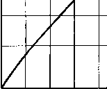  SINGLE LAYER WINDINGS L: LEAKAGE INDUCTANCE WITH TAPPED SECONDARY SHORT CIRCUITED L - LEAKAGE INDUCTANCE WITH FULL SECONDARY SHORT CIRCUITED b= WINDING WIDTH C= INSULATION THICKNESS b/C=40 I 100 80 60 40 20 0 % SECONDARY TURNS SHORT-CIRCUITED Fig. 169. Leakage inductance of asymmetrical windings. formers have been made to cover the frequency range of 50 cycles to 6,000,000 cycles, or a ratio of highest to lowest frequency of over 100,000:1. This is an exceptionally wide band. More common wideband transformers are those in the audio band of 20 to 20,000 cycles, or 10 to 30,000 cycles, that is, with about a 3,000:1 frequency ratio. Often, transformers used at frequencies on the order of 100 megacycles are for relatively narrow bands, say 20 to 60 megacycles wide. In low-impedance circuits, it is leakage inductance that determines transformer behavior, whereas at high impedance it is winding capacitance. In most audio transformers the coupling WINDINGS 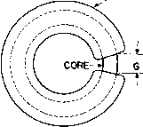 Fig. 170. Toroidal core and coil.  for inducing the secondary voltage 2 is a small percentage of the load I у V T component of current. In an air- 1 , } С Ij core transformer all the current is Fig. 17L General case of inductive exciting current and induces a sec-coupling. (mdary voltage proportional to the mutual inductance. Consider the circuit of Fig. 171 in which is complex and includes the self-inductance of the primary coil. Likewise, secondary impedance Z2 is complex and includes the self-inductance of the secondary coil. With a sinusoidal voltage applied, Kirchhoffs laws give the following: El = Zih +3<Lrnh (100) 0 = Z2I2 + icoL/i (101) where 00 = 2т times operating frequency, and is the mutual inductance between the primary and secondary coils. From equation 101 we see that the voltage in the secondary coil is iSee New 50-Watt Amplifier Circuit, by F. H. Mcintosh and Gordon J. Gow, Audio Engineering, December, 1949, p. 9. coefficient is 0.9995 or higher. With bifilar windings, this figure may increase to 0.999995. Such a high coefficient of coupling requires the use of good core materials. For a given source impedance and transformer core material, the product of turns ratio and band width is a rough indication of size. Quite generally, for low powr the widest-band transformers are made of Permalloy or Supermalloy. In high-impedance circuits the matter of size is not merely one of space for mounting; it also has a direct bearing on the upper frequency limit, since transformer capacitance is roughly proportional to size. If capacitance is low, the band-width ratio (highest/lowest frequency) is approximately equal to the ratio of OCL/leakage inductance. This may be verified by comparing Figs. 108 and 109. It is most nearly true for low-impedance transformers. With given primary impedance, core size, and material, there is a limit to the step-up turns ratio possible for any specified frequency response. 93. Air-Core Transformers. Transformers considered hitherto have had iron or ferrite cores. A class of transformers is widely used in radio-frequency circuits without cores or wath small slugs of powdered iron. In a transformer with an iron i-ni core, the exciting current required к = LJVLiL2 (104) The value of к is never greater than unity, even when coils are interleaved to the maximum possible extent. Values of к down to 0.01 or lower are common at high frequencies. Coupling coefficient is related to untuned transformer open- and short-circuit reactance by means of the transformer equivalent circuit shown in Fig. 107(a), p. 147. Assume that the transformer has a 1:1 ratio, and leakage inductance is equally divided between primary and secondary windings. Then if Li and L2 are the self-inductances of primary and secondary, respectively, L is the total leakage inductance (measured in the primary with secondary short-circuited), and L the mutual inductance, Xp H- Хлг Xs Л- Xn Ls numerically equal to oiLm.Ii, the product of primary current and mutual reactance at the frequency of applied voltage Ei. The equivalent impedance of the circuit of Fig. 171 when referred to the primary side is given by Z =Z, + {XmVZ} (102) where Хм = jooL. In the above formulas, the impedances Zi, Z2, and Z are complex quantities whose real and imaginary terms depend upon the values of resistance, inductance, and capacitance in the circuit. One common practical case arises when the primary resistance is zero, or virtually zero, and the secondary coil is tuned to resonance so that Z2 is a pure resistance R2. Under these conditions, equation 102 reduces to = XmVR2 (103) where R is the equivalent resistance in the primary. Equation 103 gives the value of mutual inductance required for coupling a resistance R2 so that it will appear like resistance R with a maximum power transfer between the two coils, and states that the mutual reactance Хм is the geometric mean between the two values of resistance. The ratio of mutual inductance to the geometric mean of the primary and secondary self-inductances is the coupling coefficient: 226 ELECTRONIC TRANSFORMERS AND CIRCUITS From equation 104, VL1L2  If U, 1 + (L,/27) к (104a) (104&) Equations 104(a) and (6) are useful in estimating approximate transformer band width. A tuned air-core transformer often used in receivers is shown in Fig. 172. Here a sinusoidal voltage may be impressed on the pri- 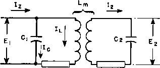 R R2 Fig. 172. Tuned air-core transformer. тагу circuit by a vacuum tube amplifier. Resistances Rt and R2 are usually the inevitable resistance of coils, but occasionally resistance is added to change the circuit response. The value of voltage E obtained from this circuit depends on the impressed frequency; in Fig. 173 it is shown for resonance at three different values of coupling. If the value of coupling is such that JCm - \7RiR2 we obtain a condition similar to that of equation 103, in whieh the maximum power or current is produced in the secondary circuit. Maximum current through condenser C2 gives maximum voltage E2. This value of coupling is known as the critical value. Smaller coefficient of coupling gives a smaller maximum value of E2. Greater coefficient of coupling results in a double hump as shown in Fig. 173. The heights of resonant peaks and frequency distance between peaks de- pend upon circuit Q and coefficient of coupling k. The double hump curve of Fig. 173 is desirable because, with modulated waves, frequencies in adjacent channels are rejected; yet very little attenuation is offered to audio frequencies which effectively add or subtract from the carrier frequency normally corresponding to resonance. Close tuning control and high Q are essential to good response and selectivity. 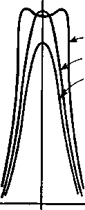 U)L<VRiR2 - 0 + CYCLES OFF RESONANCE Fig. 173. Response curves for circuit of Fig. 172. If the primary circuit is made to resonate at a different frequency from the secondary, audio response is much worse, and considerable distortion is likely. Moreover, the response at mean frequency is less than it would be if the circuits were properly tuned. Air-core transformers are usually made adjustable for tuning and coupling. 94. Multiple-Tuned Circuits. Double hump resonance was obtained with higher-than-critical coupling in the circuit of Fig. 172. Frequency response with more humps is obtainable if there are more than two coupled loops. Such circuits are more difficult to tune and adjust than the circuit of Fig. 172 because of the reaction of each coupled loop on the others. Easier adjustment can be made with successive stagger-tuned band-pass amphfiers. Each amplifier stage is tuned to a slightly different frequency. Because of the isolation of the stages by the associated tubes, tuning one stage does not influence the tuning of another. Frequency response similar to that of multiple-tuned coupled cir- cuits may be obtained by iterative ladder filter sections. In other words, it does not matter whether the coupling is inductive or capacitive; the same shape of response is obtained from the same number of circuits tuned in the same manner. Since similar results are obtained from coupled circuits and filters, the choice between them may be made on the basis of convenience or cost. Considerable literature has accumulated concerning the design and adjustment of multiple-tuned circuits, and special techniques have been developed for tuning them. 95. Mutual Inductance. It is evident from equation 101 that the secondary voltage depends upon the mutual inductance between the coils. Mutual inductance can be calculated by formulas which depend upon the geometric configuration of the coils. If the coils are arranged 1 - -2X- (a) lb) Fig. 174. Concentric coaxial coupled coils. concentrically, as shown in either (a) or (b) of Fig. 174, the mutual inductance of the coils can be found from 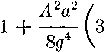 (105) where iVi - primary turns and Л^2 = secondary turns. All dimensions are in inches. For most purposes, the bracketed portion of this formula is approximately unity, and it has been plotted in Fig. 175 for a single-turn secondary. To find the mutual inductance for any given number of secondary turns, multiply the mutual inductance found from this curve by the number of secondary turns. The range of ordinates and abscissas can be extended indefinitely. If the coils are arranged coaxially as in Fig. 176, approximate values of mutual inductance are found as follows: 1 See Alignment and Adjustment of Synchronously Tuned Multiple Resonant Circuit Filters, by M. Dishal, Proc. I.B.E., 39, 1448 (November, 1951). 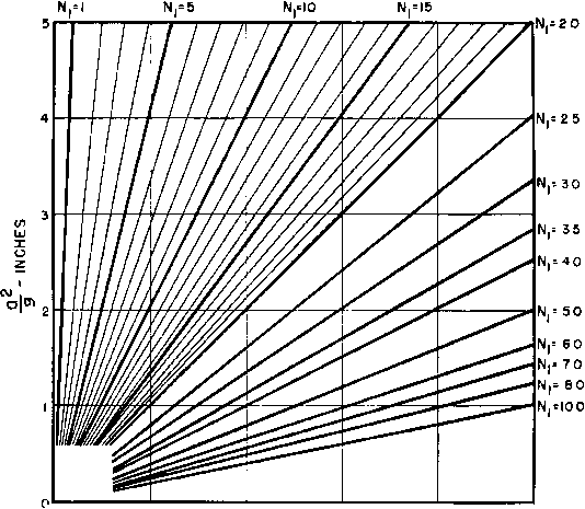 0 12 3 4 5 L,-PER SECONDARY TURN (Nl) IN MICROHENRIES Fig. 175. Mutual inductance of coils in Fig. 174.  {-if Fig. 176. Coaxial non-concentric coils with rectangular sections. .001 .0003 .0001 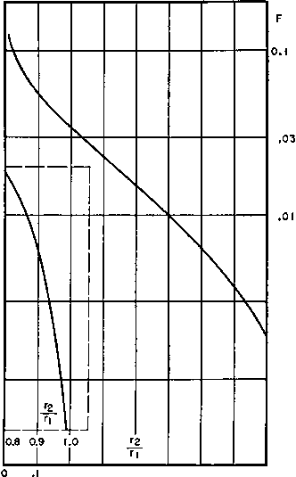 .003 .001 .7 .8 .0003 .2 .3 .4 Fig. 177. Factor F in equation 106 as a function of Гз/г^ (see Fig. 176). (106) In this formula all dimensions are in inches and the mutual inductance is in microhenrys. The factor F can be conveniently found in Fig. 177. Self-inductance of single-layer coils is OAaNK (107) where a = mean coil radius in inches N = number of turns I - length of coil in inches L = inductance in microhenrys К may be found from Fig. 178. Equations 105,106, and 107 are based on equations 192,187, and 153 in Natl. Bur. Standards Circ. 74. Receiver intermediate-frequency tuned transformers generally have coaxial coils. If the wire is more than 0.005 in. in diameter, it is commonly subdivided into several strands in the type of cable known as Litzendraht, to reduce losses and increase Q. In transmitters, the size of the coils becomes much larger, and concentric coils are employed. The wire used is Litzendraht at 600 kc or lower frequency, and may  4 5 DIAMETER LENGTH Fig. 178. Factor К in equation 107. contain many strands for carrying heavy currents. At higher frequencies the wire is of solid or tubular section. 96. Powdered-Iron Slugs. Both self-inductances and mutual inductances of a coil may be increased by inserting a slug of powdered iron inside the coil tube. Tuning a coil to a given frequency is often effected in this manner with fixed capacitors instead of tuning with variable capacitors. Such a coil is shown in Fig. 179, with the powdered-iron core hidden by the coil form. At the left end is the screw and lock by which the inductance can be adjusted and maintained at a given value. The mutual inductance of a pair of coils can be changed similarly. This is preferable to attempting to vary the distance between the coils, since it requires no flexible connections. Powdered iron is available in several grades, from ordinary powdered iron to 1 ... 20 21 22 23 24 25 26 ... 38 |
|
© 2026 AutoElektrix.ru
Частичное копирование материалов разрешено при условии активной ссылки |