 |
 |
 |
| Главная Журналы Популярное Audi - почему их так назвали? Как появилась марка Bmw? Откуда появился Lexus? Достижения и устремления Mercedes-Benz Первые модели Chevrolet Электромобиль Nissan Leaf |
Главная » Журналы » Transformer elementary form 1 ... 21 22 23 24 25 26 27 ... 38 powdered nickel alloy. Insulating compound reduces the permeability of the core to values ranging from 10 to 125, depending on the grade of iron and the frequency. In a given coil, the insertion of a powdered-iron slug raises the inductance from 2 to 3 times the value which it would have if no iron were present. Circuit Q increases similarly. Higher Q results from a powdered iron or ferrite magnetic path, closed except for small air gaps. For an untuned transformer, where high Q is not essential, the air gap may be zero to reduce magnetizing current. 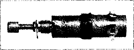 Fig. 179. Coil inductance is varied by powdered-iron slug. 97. R-F Chokes. When a choke is used to pass direct current and present high impedance to radio frequencies, it may have high r-f voltage across it. High choke impedance at operating frequency is necessary to avoid loss of r-f current which reduces the useful power and overheats the choke. If a single-layer choke is connected to an r-f generator at a given voltage, and if its current is measured as in Fig. 180, the choke impedance is the ratio of voltage to current measured. By disconnecting the choke from the circuit, the tuning reaction may be noted, and from this whether the reactance of the choke is inductive or capacitive. The difference in watts input to the generator, when the coil is removed and the tank condenser is retuned for minimum plate current, is readily observable. This difference times the generator efficiency is the loss in the coil at a particular voltage and frequency. The impedance of a typical coil, found as described above, is plotted in Fig, 180 against frequency. At low frequencies (a), the curve follows straight reactance line Xt{ = 27r/L). At a frequency somewhat below natural frequency b (determined by the choke inductance and effective capacitance), the slope starts to increase and reaches a maximum point at a frequency с of 1.26 to 1.7b. Above this frequency, the impedance decreases until a minimum value is reached at d, which is from 2.2 to 3.0 times b. At higher frequencies, the increase and decrease are repeated in a series of peaks and valleys at approximately equal frequency intervals. The second, fourth, and sixth peaks are of 35,000 30,000 25,000 20,000 t5,0Q0 10,000 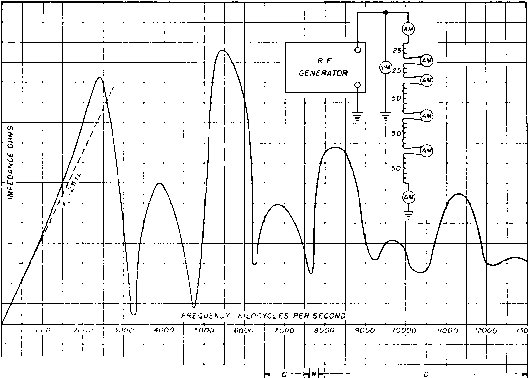 a -j - b - с --i ьо ce 100 ISO 200 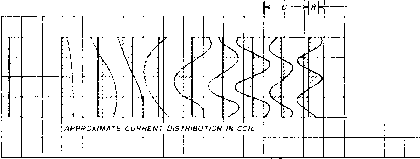 SINGLE LAYER SOLENOID гоо TURN REACTOR AMMETERS INSERTED AT EACH END ДНО AT 25,50,100 AND ISO TURNS COIL LENGTH 10 INCHES COIL INSIDE DIAMETER 4/ INCHES WIRE NO I a ROUND COPPER WIRE INSULATION D.C.C. CALCULATED INDUCTANCE 1700 MICROHENRYS Fig. 180. R-f choke impedance. lower value than the first, third, and fifth, respectively. The seventh peak is followed by a flattened slope which suggests a submerged eighth peak. The points of minimum impedance rise in value, so that at higher frequencies the valleys appear to be partly filled in and the peaks to be level off. The watts loss are high at points of low impedance, and they rise sharply at the frequency d. The change in reactance is shown in Fig. 180. The coil is inductive up to frequency b. From Ь to с it has no noticeable effect on the tuning and hence is pure resistance, or nearly so. Above с it is capacitive up to a frequency slightly below d, where it again becomes of indefinite к = coefficient of coupling = L/VZ/iLs reactance. Thereafter, it is capacitive, except for brief frequency intervals, where it is resistive, or only slightly inductive. At all frequencies higher than the fifth peak, the coil is capacitive. Since a coil has distributed constants it is subject to standing waves at the higher frequencies. The character of these waves may be found by tapping the coil at various points and inserting thermogalvanom-eters in series with the coil at these points. The current distribution is plotted in Fig. 180 against coil length. These diagrams show the kind of standing waves as the frequency increases. Current distribution is uniform at all frequencies below b. Most chokes are used within the first impedance peak. The useful range for choke impedance of 20,000 ohms in Fig. 180 is 1,700 to 2,800 kc. This choke could be operated at 5,500 kc safely also, but the frequency range is narrower. Also, the safe loss dissipation is less because it takes place over half of the coil surface. Pie-section chokes have similar impedance curves, but impedance peaks following the first are less pronounced. 98. Large Power Coupling Coils. In the tank circuits of large power amplifiers, the coupling coils are arranged to couple the antenna to the power amplifier, and the equivalent circuit is like that of Fig. 172. Optimum coupling between tank and antenna circuits is given by equation 103. The construction of the coupling coil itself is usually similar to that of Fig. 174(6), with the coupling coil on the outside and spaced from the main tank coil to reduce capacitive coupling. Taps are provided on the coupling coil for frequency and antenna resistance adjustments. When the secondary circuit is untuned, and the secondary load is reactive, all the secondary volt-amperes (which may exceed the secondary watts many times) flow through the transformer windings. It is then necessary that tight coupling be used between primary and secondary in order to prevent loss of poww, due to current circulating in the primary without corresponding current flowing in the load. If the load power factor is less than 20 per cent, currents and volt-amperes in the circuit may be considered independent of the winding and load resistances. In Fig. 171, let the load Z2 be inductive, comprising L3 and Rl. Also let Й1 = 0 Li = primary self-inductance L2 = secondary self-inductance Lm = mutual inductance 2(1 + Vl - - fc2 (108) This equation is plotted, together with values of ratio L3/L2 for maximum power transfer, in Fig. 181. If perfect coupling could be attained, ro I Q < I.O .9 .8 .7 CVJ IM CVJIM x .5 < s .2 .1
0 0.1 0.2 0.3 0.4 0.5 0.6 0.7 0.8 0.9 1.0 К Fig. 181. Effect of coupling on maximum volt-amperes in untuned load. all the primary volt-amperes could be transferred to the load. Iron-core transformers operate at the extreme right of Fig. 181. With air-core transformers it is often difficult to approach this condition, especially if voltages are high. 99. High-Frequency Power Supplies. In cathode-ray tubes for oscilloscopes or television receivers, high-voltage low-current sources of d-c power are needed for the accelerating anodes. Voltages range from 1 to 30 kv, and currents are on the order of 1 ma down to 1 /га. Because of the many turns of wire required in high-voltage 60-cycle transformers, high-frequency power supplies are often used. A tetrode or pentode tube is used in a double-tuned circuit as shown in Then the secondary volt-amperes = 122, and primary volt-amperes = Ell i. The ratio of maximum secondary volt-amperes transformed to the primary volt-amperes is related to к as follows: Fig. 182. Here the plate circuit is tuned by means of elements Li - Ci, and the load circuit by means of L2 - C2. The grid winding is coupled from Li. The coupling between Li and L2 is usually higher than critical, so that changes in load do not affect the resonant frequencies, but instead vary the relative height of the two humps. In general, the transformer represented by inductances Li and L2 9z >\ 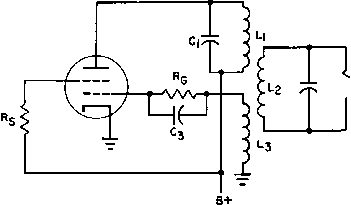 Fig. 182. R-£ power supply. is step-up. Load Rl may be a voltage doubler, tripler, or quadrupler, depending on the voltage needed from the oscillator. Frequencies used in such power supplies range from audio to medium high radio frequency. The oscillator is usually operated class В or C; loaded Q (or ratio of volt-amperes to watts) ranges from 10 to 20. Lower values of Q result in oscillator instability with load changes. With ferrite cores, departures from the overcoupled case are feasible. Frequency is usually lower than with air-core transformers. The core itself affords a certain amount of load to the circuit and therefore results in better voltage regulation from load-on to load-off conditions. The single-tuned oscillator of Fig. 152 then becomes practical. iSee Radio-Frequency-Operated High-Voltage Supplies for Cathode-Ray Tubes, by 0. H. Schade, Proc. I.R.E., 31, 158 (April, 1943). 8. ELECTRONIC CONTROL TRANSFORMERS Electronic devices are used to control speed, voltage, and current, or may require control of these quantities. Most of the circuits can be grouped into a few basic types. This chapter comprises typical circuits which use transformers and reactors. 100. Electronic Control Circuits. Vacuum-tube control circuits are used for amplification of the input voltage, not always at a single LOAD 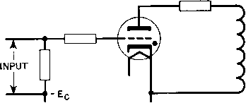 60 CYCLE SUPPLY ANODE VOLTAGE Fig. 183. Basic thyratron circuit. frequency. With thyratrons the input voltage triggers the tube, which then allows current to flow into the controlled circuit, but the output wave may not resemble the input wave, as is described below. A simple circuit for thyratrons operated with alternating anode supply and resistive load is shown in Fig. 183. During that part of each cycle when the anode is positive with respect to the cathode, the tube conducts current which passes through the load, provided that the grid is at he right potential. In Fig. 184 is shown the positive anode voltage for a half-cycle, with the 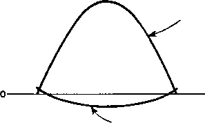 A-C CRITICAL GRID VOLTAGE Fig. 184. Anode and critical voltages in basic thyratron circuit. 1 See Industrial Electronics, by F. H. Gulliksen and E. H. Vedder, John Wiley & Sons, New York, 1935, p. 45. corresponding critical grid voltage. Any value of grid voltage higher than this critical value will permit the tube to conduct. Once tube conduction is started, change of grid voltage to a value less than criti- ANODE VOLTAGE D-c GRID INPUT VOLTAGE 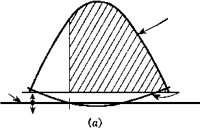 CRITICAL GRID VOLTAGE A-c GRID VOLTAGE D-C GRID VOLTAGE 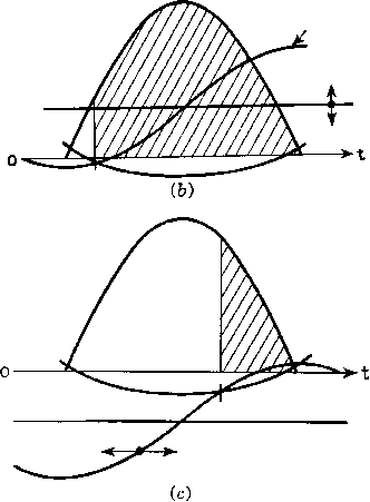 D-c GRID VOLTAGE X A-c GRID VOLTAGE Fig. 185. Grid control of a thyratron tube with (a) variable d-c grid voltage, (b) variable d-c grid voltage with superposed a-c grid voltage, (c) fixed d-c grid voltage with superposed a-c grid voltage of variable phase position. cal will not stop conduction. Conduction does stop, however, at the end of the half-cycle, or when the anode voltage falls to zero. Three methods of controlling the load current are shown in Fig. 185. Figure 185 (a) shows how direct voltage applied to the grid permits conduction through the tube over the shaded portion of the cycle. Minimum con- trollable current is half that which would flow if the tube were free to conduct over the entire positive half-cycle. This method of control is not precise, especially near the half-power point, because a small difference in d-c input control voltage produces a comparatively large change in conduction angle or may cause the tube to fail to fire altogether. Figure 185(6) shows a more satisfactory method of amplitude control. The grid is maintained at a positive d-c potential, and an alternating voltage is superposed on it which lags the anode voltage by 90°. Varying the magnitude of the d-c grid voltage shifts the zero axis of the a-c wave up or down, and intersects the critical a-c grid voltage at different points of the cycle. Tube current can then be varied from zero to maximum. Close control of the tube current can be obtained because the grid voltage wave intersects the critical curve at a large angle. In Fig. 185(c) another method is shown. The phase of a superposed alternating voltage is shifted upon a negative d-c bias which is more negative than the critical characteristic. Changing the phase position of the a-c grid voltage varies the tube current from zero to maximum. The phase position of the grid voltage can be shifted by several methods, one of which is discussed in Section 101. The anode supply transformer carries load direct current. Core saturation may be prevented by an air gap; heating and regulation in the primary winding due to excitation current govern the length of air gap. Ordinarily, permissible maximum induction may be higher than in a single-side amplifier transformer because impedance or frequency response considerations are irrelevant with a 60-cycle supply line. Excitation current may be comparable in magnitude to load current. However, there is this difference: with a resistive load, current flows only during the positive half-cycle, whereas magnetizing current flows during the whole cycle. Secondary current is a series of pulses, the maximum width of which is 180°. The rms value of these pulses is half the peak amplitude, and this is the current which governs secondary wire size. Rms secondary voltage is 2.22 times maximum d-c load voltage, as in a single-phase half-wave rectifier. Design of the transformer is similar to the anode transformers in Chapter 3, except for the higher induction and current wave form. Full-wave circuits operate лvith two thyratrons and a center-tapped transformer in which the net d-c fiux is zero. The design of the anode transformer is described in Section 102. 1 See Gulliksen and Vedder, op. cit., p. 54. 101. Grid-Controlled Rectifiers. The basic a-c grid control circuit described in the last section may be extended to more than one tube and may control large amounts of power. Any of the rectifier circuits of Table VII (p. 62) may be used with grid control of output voltage, which supplants the older practice of using induction regulators in the supply lines. Smooth control of rectifier d-c voltage under load conditions is possible through the use of thyratrons or ignitrons with phase-shift control of the grid or igniter. Stable control of filtered output is possible only with choke input filters. In Chapter 4 the regulation of a rectifier is shown to be lowest if the input choke has inductance greater than critical value. With grid control, if the filter choke inductance is great enough, the tube conducts even after the anode reaches zero. The tendency of current to stop at voltage zero builds up voltage across the filter choke in such a direction that cathode potential is less than zero after the anode reaches zero. Thus conduction in the tube is maintained until the next tube fires. If the choke inductance is less than critical, tube current wave is discontinuous, regulation is poor, transient surges and oscillations in the output voltage occur, and control is unstable. For a single-phase full-wave rectifier with grid control, the direct voltage output decreases as shown by curve I in Fig. 186. Critical value of inductance increases with firing angle and so does ripple voltage as shown by curves II and III in this figure. For a three-phase full-wave rectifier, the direct output voltage is approximately 41 per cent greater than the single-phase values shown in Fig. 186, and the critical value of choke reactance less filter capacitor reactance is approximately one-tenth of the single-phase values over the range of 20° to 90° firing angle. At 90° firing angle, the d-c output always is zero. Voltage across the choke reverses in sign but does not increase in magnitude even with the maximum angle of 90°. Therefore the maximum voltage from choke to ground is not changed, and the design of a reactor for this type of rectifier is the same as for a rectifier without grid control, except for the value of inductance. Choke-input filters can be used to maintain continuous current flow in single-phase half-wave rectifiers. Although the output voltage is reduced, as mentioned in Chapter 3, this combination is occasionally useful. 1 For general calculation of discontinuous waves, see Voltage and Current Relations for Controlled Rectification with Inductiл'e and Generative Loads, by K. P. Puchlowski, Trans. AIEE, 64, 255 (May, 1945), For theory of controlled Grid-controlled rectifiers have more irregular current wave forms and therefore more pronounced a-c line harmonics than ordinary rectifiers/ Two methods of providing phase shift control of a constant amplitude a-c grid voltage for grid-controlled rectifiers are shown in Fig. 187. In > H 1.0 a. о о 0.8 ы 07 06 05 0.4 03 02 0.1 О Xl= first inductor reactance at RIPPLE frequency FIRST CAPACITOR REACTANCE AT RIPPLE FREQUENCY RpMAX, LOAD RESISTANCE EqcIoc CONTINUOUS CURRENT I I MULTIPLY Xi-X, BY ORDINATE OF CURVE Ш TO FIND RIPPLE 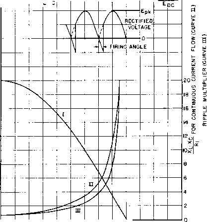 20 30 40 50 60 70 80 90 FIRING ANGLE IN DEGREES Fig. 186. Output voltage, ripple, and current continuity in single-phase full-wave grid-controlled rectifier. (a) a small value of resistance R effectively connects the upper grid circuit terminal to the left-hand terminal of the supply transformer, and a large value of R shifts it nearer to the right-hand terminal of the rectifiers, see Critical Inductance and Control Rectifiers, by W. P. Overbeck, Proc. I.R.E., m, 655 (October, 1939). 1 See Harmonics in A-C Circuits of Grid-Controlled Rectifiers and Inverters, by R. D. Evans and H. N. Muller, Jr., Trans. AlEE, 68. 861 (1939). 1 ... 21 22 23 24 25 26 27 ... 38 |
||||||||||||||||||||||||||||||||||||||||||||||||||||||||||||||||||||||||||||||||||||||||||||||||||
|
© 2026 AutoElektrix.ru
Частичное копирование материалов разрешено при условии активной ссылки |