 |
 |
 |
| Главная Журналы Популярное Audi - почему их так назвали? Как появилась марка Bmw? Откуда появился Lexus? Достижения и устремления Mercedes-Benz Первые модели Chevrolet Электромобиль Nissan Leaf |
Главная » Журналы » Transformer elementary form 1 ... 22 23 24 25 26 27 28 ... 38 supply transformer. If the supply transformer is center-tapped, the vector diagram of Fig. 188 shows the phase position of the grid voltage Eg in solid lines for a small value of R, and in dotted lines for a large value of R. Varying the rheostat R thus varies the rectifier output from full voltage to a low voltage. TO GRID CIRCUIT -► TO 60 CYCLE SUPPLY TO D-C CONTROL VOLTAGE 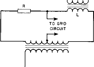 TO 60 CYCLE SUPPLY Fig. 187. Resistance-inductance phase shift circuits. In Fig. 187(b) resistor R is fixed and inductance L is varied by means of direct current flowing in one of its windings. The vector diagram of Fig. 188 still applies; the sohd lines are for high inductance and the dotted lines for low inductance. Direct current for varying the inductance may be obtained through a thyratron or a vacuum tube, especially when rectifier output voltage is automatically controlled. The reactor is usually of the saturable type. 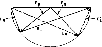 Fig. 188. Vector diagram for Fig. 187. 102. Thyratron Transformers. Anode transformers used for supplying thyratrons resemble rectifier anode transformers but generally have higher rms current for a given direct current in the load, and are more subject to voltage surges. With resistive loads, anode current has the same wave shape as the shaded portion of the anode voltage in Fig. 185. The relation of peak, rms, and average currents is shown in Fig. 189 as a function of firing angle в for single-phase full-wave circuits. Voltage reduction as a function of в is shown in Fig. 190. If a transformer is designed for operation with zero firing angle, maximum current flows in any given load; the transformer is then capable of carrying the current with greater firing angle, so long as the load impedance remains the same. If the load impedance is changed with i9 > 0 to keep the load current as high as possible, the limiting value may be found from Fig. 189. The average load current which may flow without overheating the transformer decreases as В increases. High-voltage surges occur when capacitance input filters are used with grid-controlled rectifiers. To a degree these surges are likely to occur even when the load is nominally resistive, because of incidental capacitance in the transformer, wiring, and other components. If the load is a radio-frequency generator, the r-f bypass capacitor adds to this effect. In Fig. 191 (a) the total amount of external capacitance is designated Cx. A half-wave anode transformer is shown for simplicity, but each half of a full-wave transformer, or each phase of a three-phase transformer, behaves similarly. When the thyratron firing angle is The widest range of inductance is obtained with zero direct current at the higher inductance. In some vacuum-tube circuits, the minimum direct current is not zero, and a bias winding is added to the center leg to cancel the d-c ampere-turns with minimum current in the main d-c winding. Saturable reactors have many uses besides that described here, and are discussed more fully in Chapter 9. greater than zero, a steep voltage wave front occurs at the instant of firing t, Fig. 191(b), as follows: Normal voltage induced at point A in the secondary winding is volts above ground, just prior to fg. As soon as the thyratron fires, 2 CE H
0 15 30 45 60 75 90 105 120 135 150 165 180 FIRING ANGLE 9 (DEGREES) Fig. 189. Single-phase thyratron currents. the external wiring and circuit capacitance Ci momentarily forms an effective short circuit from A to ground. A large surge current flows into this short circuit, but initially this current cannot be drawn from the primary because of the inevitable inductance of the windings. The initial current is therefore supplied by the secondary winding capacitance. Since point A is momentarily short-circuited, a surge voltage, equal and opposite to ei, is developed in the secondary winding. This voltage surge appears across the turns or layers of winding nearest to A. Unless precautions are taken in the design of the anode trans- former ttie voltage may be high enough to damage the winding insulation. As is shown in Chapter 10, with steep wave fronts in single-layer windings initial voltage distributes most equally between turns when ratio a = л/Сд/С^ is small, Cg being the capacitance of the winding to ground and the series capacitance across the winding. If the secondary of Fig. 191 were a single- 70 60 50 40 g 30 Ш ш Ш
e IN DEGREES layer winding of n turns, Cw would be Cs/n. In multilayer coils, ratio a is not so readily defined. In general, small effective layer-to-layer capacitance means small effective Cg in relation to Cw, small a, and more linear initial distribution of voltage. Many layers are better than few layers in keeping capacitance Cg small. In the limit, a one-turn-per-layer coil would have small a and good initial voltage distribution. In practice this extreme is not necessary to avoid layer insulation breakdown. It is usually sufficient to split the secondary into part coils, like Si and in Fig. 59. This reduces Cg to a quarter of the corresponding capacitance of full-width coils. Ratio a is reduced, and voltage distribution improved. Even with part coils there is some non-linearity of voltage distribution, especially in the top layer. This non-linearity may be minimized by providing a static shield over the top layer and connecting it to point Л, Fig. 191. The momentary voltage described above appears within the winding, and unless there are taps it may not be observable. If a surge suppressor circuit (usually a capacitor-resistor network across the secondary) is used, it does not appreciably diminish the internal winding voltage surge, but such a surge suppressor may be necessary to damp out oscillations in the external circuit due to firing of the th ratrons. 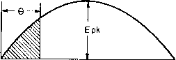 Fig. 190. Relation of firing angle to voltage output. Secondary windings of control transformers in thyratron grid circuits, like those of Fig. 187, should be insulated for the anode voltage. When thyratrons arc-back the grids may be subjected to full anode potential, which would damage lesser amounts of insulation. 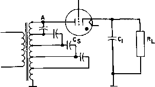 lo) SCHEMATIC CONNECTIONS FOR EACH PHASE
(b) SECONDARY VOLTAGE 65 AND CURRENT ig WITH PHASE-BACK Fig. 19L Thyratron plate transformer operation. 103. Peaking Transformers. It is stated in Section 100 that a large angle of intersection between the grid firing voltage wave and critical grid voltage is desirable for accurate control. A grid wave form with vertical front edge would be ideal. To produce a steep peaked wave form for firing thyratron tubes, sometimes special transformers are used. Usually the design depends on the non-linearity of the magnetizing current. Figure 192 shows a peaking transformer in which the magnetic core is made of special laminations. The primary is wound on the full-width left leg, and the secondary on the right leg which is lade of a few laminations of small width. In the space between primary and secondary is a laminated shunt path with an air gap. In Fig. 193 are shown the core fluxes ф,п and linking the primary and secondary coils, respectively. At low inductions, the same flux links both coils. As the flux rises from zero in each cycle, at first all the PRIMARY A-C SUPPLY 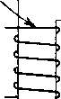 MAIN CORE SHUNTS AIR GAP SECONDARY CORE LEG SECONDARY OUTPUT VOLTAGE Fig. 192. Peaking transformer. flux links the secondary coil, but because of the smaller cross section of the right leg it saturates at the value фа and the main flux фт flows through the shunt path. Thus there is a long interval in each cycle during which the flux change is substantially zero, and no voltage is induced in the secondary coil. During the short period dg, a voltage is induced in the secondary coil which has a very peaked wave form. This happens twice in each cycle. Because of the shorter time for the change in ф^, (1ф/(И would remain nearly constant over the angle Og if there were no leakage flux, and for 1:1 turns ratio there would be approximately equal volts in the primary and secondary coils. The secondary flux change takes place over a much shorter period of time, and the flux rises to only a fraction of its maximum value ф„ . Therefore less core area is needed in the secondary leg to obtain the desired voltage eg. This leads to the following approximate ratio. 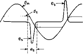 Fig. 193. Fluxes and secondary voltage in peaking transformer. = - sm - (109) where Ag An core area in the secondary leg core area in the primary leg. Peaked secondary voltage may be made steeper by the use of nickel-iron laminations in the secondary leg, because these alloys have sharp saturation. The air gap in the center leg prevents it from shunting all the primary flux, which would reduce the secondary voltage to zero. where = secondary turns = allowable induction in the shunts (in gauss). This air gap should be no more than 5 to 10 per cent of the window height, to keep leakage flux from threading through the secondary coil and giving a less peaked wave form. With this length of air gap and a total window length of twice the window height, the secondary turns are, for a 1:1 voltage ratio, Ns - 2Np (110) where Np is the number of primary turns. Transformers may be made to peak by the use of special circuits instead of special cores. Voltage wave forms like Fig. 193 are obtainable if the primary winding is operated at a voltage exceeding saturation but is connected in series with a large linear inductance or other high impedance. Grain-oriented core material, with its rectangular hysteresis loop, is well suited to peaking transformers. When primary and secondary windings are wound over the same magnetic path, the same volts per turn are induced in both windings, and equation 110 no longer applies. A peaking reactor circuit is shown in Chapter 11, Fig. 262. 104. Current-Limiting Transformers. Filaments of large vacuum tubes sometimes must be protected against the high initial current they draw at rated filament voltage. This is done by reducing the starting voltage automatically through the use of a current-limiting transformer, with magnetic shunts between primary and secondary windings. The shunts carry very little flux at no load; as the load increases, the secondary ampere-turns force more of the flux into the shunts until at current Igc, Fig. 194(Б), the output voltage is zero. The same principle is used to limit current in transformers for oil-burner ignition, precipi-trons, and neon or other gas-filled tube signs. Cross-sectional area through each shunt path is the same as that of the upper or lower leg of the shell laminations; then flux in the shunts does not exceed that in the core, shunt iron loss is not abnormal, and secondary voltage is sinusoidal. At short-circuit current Igc, half the total flux flows through each set of shimts. The air-gap length in each shunt path can be found from equation 35: omisc =- (inches) The constant 0.6 is generally too small because of the flux fringing around the gap. The increase of gap made necessarj by fringing may be found from Fig. 72 (p. 102). If the shunts are too short, the transformer does not limit the current properly. It is best to have slightly less air gap than necessary, and find by trial the right length of AIR GAP MAGNETIC SHUNTS 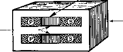 MAIN CORE P= PRIMARY WINDING SECTION S= SECONDARY WINDING SECTION OPEN-CIRCUIT VOLTAGE SECONDARY VOLTAGE 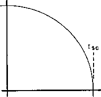 SECONDARY LOAD CURRENT Fig. 194. (Л) Current-limiting transformer; (B) output voltage versus current curve. shunt. Fringing flux heats the coils and core somewhat more than in an ordinary transformer. If the secondary current is heavy, coils are wound pancake fashion and connected in parallel; they may have to be cross-connected for the coils to divide the load equally. If the ordinate for open-circuit voltage and abscissa for short-circuit current in Fig. 194(Б) are equal, the curve is a quarter-circle for a perfect transformer because the secondary current at short-circuit is all reactive. With core, shunt, and winding losses the curve for an actual transformer falls some 10 to 15 per cent less than the quarter-circle at currents 0.5 to 0.75 times J.e- Fig. 195. Autotransformer voltages and currents. 105. Autotransformers. An autotransformer has a single winding which is tapped as shown in Fig. 195 to provide a fraction of the primary voltage across the secondary load. The connections may be reversed so that a step-up voltage is obtained. The regulation, leakage inductance, and size of an Ь * autotransformer for a given rat- ing are all less than for a two-winding transformer handling the same power. Where the voltage difference is slight, the gain is large. Where the voltage difference is great, there is not much advantage in using an autotransformer, nor can it be used where isolation of the two circuits is required. Autotransformers are used in electronic applications chiefly for the adjustment of line voltage, either to change it or to keep it constant. Examples are the reduction of plate voltage for tuning an amplifier and the maintenance of constant filament voltage. Taps may be chosen by means of a tap switch to adjust the load voltage. The load voltage may be adjusted to within half the voltage increment between taps. If the voltage is adjusted while load remains connected, bad switching arcs occur, either from breaking the circuit or from short-circuiting turns. To provide for adjustment under load conditions, a resistor may be momentarily connected in the circuit as the tap switch bridges from one tap to the next, and current is limited to full-load value. In large power tap changers, a reactor replaces the resistor to avoid heating and losses. The v-a rating of an autotransformer depends on the ratio of input to output voltage. In Fig. 195 the output current I2 = h -\- h. Let p = per cent tap/100 = E2/E1. Neglecting losses, I2 = h/p and I, = {1/p - l)7i. Then Volt-amperes (in the upper portion) = (1 - p)EiTi Volt-amperes (in the loiver portion) = pEiI = (1 - p)EiIi which satisfies equality of volt-amperes in each section. For ratio p close to unity, the v-a rating and hence size for a given output can be made very small; for small values of p the size is not much less than that of a two-winding transformer, but the autotransformer has much less regulation. Its effective winding reactance and resistance decrease as (1 - p); that is, for a given unit, X (or R) as autotransformer X (or R) as two-winding transformer = (1 - pY (111) Appreciably less regulation is obtained in an autotransformer, even when size is not reduced much, because the right-hand term in equation 111 is squared.    Fig. 196. Adjustable pnmary anode transformer. When the power for electronic equipment is supphed by a 230-volt line, but auxiliary items such as relays and small motors are used at 115 volts, a convenient way of obtaining the latter voltage is to center-tap the primary of a large plate transformer, and use it as a 2:1 step-down autotransformer. The larger primary winding copper requires little extra space, and an additional transformer is thereby saved. To improve the closeness of voltage control, a variable autotransformer has been develo ed in which the moving tap is a carbon brush 1 ... 22 23 24 25 26 27 28 ... 38 |
||||||||||||||||||||||||||||||||||||||||||||||||||||||||||||||||||||||||||||||||||||||||||||||||||||||||||||||||||||||||||||||||||||||||||||||||||||||||||||||||||||||||||||||||||||||||||||||||||||||||||||||||||||||
|
© 2026 AutoElektrix.ru
Частичное копирование материалов разрешено при условии активной ссылки |