 |
 |
 |
| Главная Журналы Популярное Audi - почему их так назвали? Как появилась марка Bmw? Откуда появился Lexus? Достижения и устремления Mercedes-Benz Первые модели Chevrolet Электромобиль Nissan Leaf |
Главная » Журналы » Transformer elementary form 1 ... 23 24 25 26 27 28 29 ... 38 which slides over exposed turns of the winding. Brush resistance prevents excessive transition current and permits smooth voltage control; yet it offers little additional series resistance to the load. The same idea can be applied to two-winding transformers for secondary voltage adjustment. A typical unit of this kind is shown in Fig. 196. When autotransformers are used on three-phase supply lines, they may be connected the same as two-winding transformers in star, delta, open-delta, or Scott connections. The last two connections are less subject to objectionably high regulation in autotransformers and, if they supply three-phase anode transformers, cause no serious primary voltage unbalance for voltage ratio p close to unity. 106. Static Voltage Regulators. Automatic regulators of various kinds have been devised for keeping comparatively small amounts of power at a constant voltage. Figure 197 shows one circuit for a res- 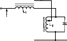 A-c SUPPLY LINE VOLTAGE OUTPUT VOLTAGE Fig. 197. Resonant-circuit voltage regulator. onant-reactor voltage regulator. Inductance Li is linear. Inductance L2 and capacitor C2 are parallel-resonant at the supply line frequency and rated voltage. The pair draws very little current, so that the reactive voltage in Li is low. Output current flows through its secondary winding which is of such polarity as to maintain rated voltage. Inductance La is partially saturated at this voltage. If line voltage falls below rated value, less current is drawn by L2, and the L2C2 combination becomes untuned. Total current to the parallel circuit is then capacitive, and this capacitive current, drawn through Li, raises the output voltage. Conversely, if line voltage rises above rated value, the L2C2 combination becomes untuned on the inductive side, and the output voltage falls below the line value. Output voltage variations of =bl per cent are obtained with =ь10 per cent line voltage variations in this manner, and with load changes from zero to full load. Constant supply frequency is a condition for resonance at rated voltage; with the good frequency control of modern power systems this condition is generally fulfilled. Load power factor variations cause output voltage to change. Some regulators are provided with taps to minimize this effect. Output wave form contains a noticeable third harmonic, because the large magnetizing current of L2 must flow through appreciable impedance in Li. Owing to the partial saturation of reactor L2, it tends to operate at a high temperature and requires good ventilation. Practical regulators are in use with ratings from 25 v-a to several kva. UNREGULATED D. C. SUPPLY SERIES R -WW ANODE VOLTAGE V-R REGULATED TUBE D. C. OUTPUT 0 5 10 15 20 25 ANODE MILLIAMPERES Fig. 198. Voltage regulator characteristic. Electronic voltage regulators make use of a gas-filled regulator tube, which has a v-a characteristic such as that shown in Fig. 198. Current drawn by this tube changes between wide limits with virtually no change in voltage. A series resistor is ordinarily used to limit the current. When output current in excess of the V-R tube rating is desired, it may be used as a voltage reference for a current amplifier. Some voltage regulators amplify the difference between a voltage reference and the output voltage of a rectifier or generator. This difference is called the error voltage. The amplifier output reduces the generator field if generator output voltage is high and increases the field if the output voltage is low. Likewise, motor speed may be regulated by the difference between tachometer output and a voltage reference. Or the angular position of a motor may be controlled elec-tricall as desired b remote means. These means are discussed in books on servomechanisms. If a thyratron amplifier is used as part of a servo system, one thyratron may produce an effect opposite to that of the other, such as reversing current in the load. This amplifies the power controlled by error voltage. In many modern regulator and servo systems, magnetic amplifiers are used. These devices are described in Chapter 9. 107. Demodulators. Demodulators or detectors measure phase or amplitude variations which are used to convey intelligence or control 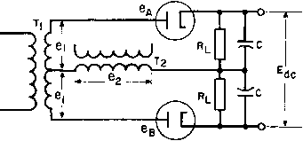  e, Br Fig. 199. Phase-difference demodulator, another device. A circuit often used for phase detection is shown in Fig. 199. Transformer Ti has a balanced secondary with Ci volts per side. In frequency or phase demodulators, the circuit is called a discriminator, and uses air-core transformers. This circuit is used in phase demodulation to produce a d-c voltage proportional to phase shift. In this case 62 leads ei by 90° for zero output. This condition is shown in the upper vector diagram. If e should lead the upper ei by less than 90°, would increase and Св decrease, causing a net d-c voltage to appear across the output. If 62 should lead the lower Ci by less than 90° the d-c output voltage would change polarity. The plate voltage of one diode is the vector sum of ei and e, and is 90° out of phase with the plate voltage of the other diode {which is the vector difference of e and 62). If the phase angle ф between Ci and 62 changes either positively or negatively, output voltage Ea is very nearly proportional to ф, up to ф = ±60°. For positive phase shift, the output Eac is negative; for negative phase shift, Eac is positive. For good linearity, load resistances Rl should be large compared to the diode resistances. Modifications of this circuit made to eliminate the vector difference 1 See Principles of Servomechanisms, by G. S. Brown and D. P. Campbell, John Wiley & Sons, New York, 1948. voltage or to reduce the degree of amplitude modulation are known as balanced and ratio detectors. As used in servo control, the demodulator produces d-c output which changes polarity when one voltage reverses with respect to the other; in this case 62 adds directly to one voltage and subtracts from the other. The lower vector diagram shows how a voltage 62 - e causes a low difference voltage on diode A and a large sum voltage on В to produce a net d-c output voltage. Transformers in phase-reversal demodulators are usually iron-cored. Both transformers Ti and T2 RECTIFIED LOOPS MODULATION 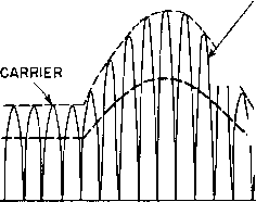 ENVELOPE Л .AUDIO  WAVE  Fig. 200. Rectified amplitude-modulated wave. should have low exciting current so that the phase angle between the voltages to be measured is not appreciably increased. For the same reason, the source impedances should be small; when this is not possible, the transformers should be matched. Figure 131 shows how necessary this is. With equal source and load resistances, several degrees of phase shift are introduced even if the ratio of transformer reactance to source resistance is 10:1. Variations in this reactance cause errors in the phase-demodulator output. In a-m receivers, the received signal is modulated radio frequency. If 100 per cent amplitude modulation is used, the r-f amplitude is varied from 0 to 200 per cent at an audio-frequency rate. The detector, or demodulator, of the receiver first rectifies the r-f signal and then eliminates the r-f component, leaving only audio frequencies in the output. A rectified signal, before the r-f is eliminated, is shown in Fig. 200. Demodulation is accomplished in the circuit of Fig. 201 by means of diode 6H6-2. Each half of the r-f cycle is rectified and the d-c iSee Diode Phase-Discriminators, by R. H. Dishington, Proc. I.R.E., 37, 1401 (December, 1949); also, Radiotron Designer s Handbook, F. Langford-Smith, RCA Victor Division, Harrison, N. J., p. 1088. power is absorbed in resistor 3. Audio power is bypassed around i?3 by capacitor C2, and the voltage is impressed upon the primary of transformer T2. If an amplitude-modulated wave is used in this amplifier, the output voltage of winding &i on transformer Ti has the form shown in Fig. 200. The first few cycles are shown as full-wave rectified loops with constant amplitude, that is, with no modulation. The audio output for this section of the wave is zero. A sine-wave envelope of 100 6SK7 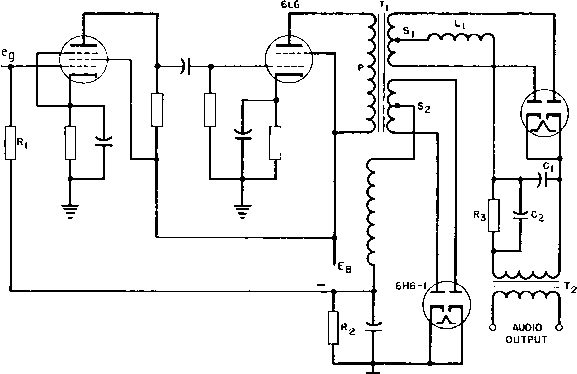 6H6-2 Fig. 20L Demodulator and automatic gain control circuits. per cent modulation is shown in the rest of the figure. Average voltage left after the carrier frequency half-loops have been absorbed by the r-f filter LC-i is the audio voltage impressed on transformer T2. The method of demodulation just described is known as diode demodulation. It is often accomplished by means of a single diode, and then every other lobe of the wave in Fig. 200 is omitted. Methods are in use also for demodulation with a triode, in which some ampHfica-tion of the demodulated wave is obtained. 108. Automatic Gain Control. Vacuum-tube amplification factor is constant under certain conditions of operation. With high current operation the amplification factor in the region of high anode current and low anode voltage is no longer constant. Some tubes are designed to have large variations in amplification factor. These are known as variable-mu, remote cut-off, or super- control tubes. The mutual conductance of such tubes is highly variable with grid bias. Figure 202 is the curve of mutual conductance for a tube of this kind. Such a characteristic can be used to reduce gain at high amplitudes and thus prevent overmodulation in audio 2500 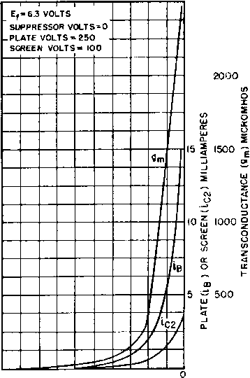 -50 -40 -30 -20 -10 CONTROL-GRID VOLTS Fig. 202. Variable-mu tube (6SK7) mutual conductance curve. systems. In Fig. 201 the circuit shown automatically reduces gain for excessive values of applied grid voltage вд on the grid of the 6SK7 tube. This tube drives a 6L6 output tube through transformer T. On this transformer there is an auxiliary winding So which is connected to rectifier tube 6H6-1 and produces the rectified output across resistance having a negative potential at the point shown. With large signals, the voltage rectified across R2 is large and reduces the mutual conductance and plate voltage swing of the 6SK7 tube. Nearly constant output voltage is maintained in the 6L6 output. If the power output of the 6L6 tube is delivered mainly into a linear a-c impedance, the slight additional load imposed by the gain control makes little difference. But if all the output is delivered to rectifier loads, as it is in Fig. 201, the non-linearity of both tube and load causes output distortion. This is true particularly of beam or pentode output tubes. The normal class A output of a 6L6 beam tube is 6 watts but, if the output power is all rectified, only 50 mw can be drawn лvithout excessive distortion. Half-wave rectifiers and capacitor-input filter outputs are wrst in this respect, because of the current discontinuities. If the automatic gain control rectifier input is taken from a tuned amplifier, these difficulties decrease. The tuned circuit capacitor readily supplies irregular current wave forms, provided the amplifier has sufficient power output available. Automatic volume control (AVC) is applied in receivers to either the r-f or audio stages, to maintain approximately constant volume in spite of fading or other causes of input voltage variations. It is applied in audio amplifiers to maintain better output volume with differing voice loAels. If the input grid resistor Ri in Fig. 201 is connected to a fixed negative bias the AVC is inoperative below the value of bias voltage. This is called delayed AVC; with it, no AVC is applied until a certain output level is reached. In some receivers, more than one stage may be controlled, and the AVC action is amphfied. Circuits similar to this are used in power-line carrier receivers. The carrier frequency is 40 to 200 kc, and audio frequencies are employed for modulation. In transformer Ti some special problems are encountered because the transformer operates over a range of 40 to 200 kc, delivers the correct amount of voltage to the automatic gain control tube 6H6-1 for proper AVC action, delivers the proper output to the audio load without distortion, and obtains these voltages from a nearly constant current source. The transformer ratio is obtained by estimating the r-f voltage swing obtained with a square primary input current wave, and dividing this by the voltage required to produce the necessary audio output after choke Li smooths the rectified lobes to the average value shown by the heavy dotted lines in Fig. 200. Transformer voltages and currents are calculated as in Table VII (p. 62) for a single-phase full-waл'e rectifier, but with peak audio current and voltage taking the place of d-c output. 9. MAGNETIC AMPLIFIERS Amplifiers with saturable reactive elements are known as magnetic amplifiers. Such amplifiers have been built with power gains of over 1,000,000. Compared with electronic amplifiers, magnetic amplifiers have the advantage of long life. It is the purpose of this chapter to describe the operation and design of elementary magnetic amplifiers. 109. Saturable Reactors. From the fundamental theory of transformers, it will be recalled that the voltage induced in a winding usually far exceeds the resistance drop in that winding. In other words, winding open-circuit reactance usually is much greater than winding d-c resistance. Further, it will be recalled that a relatively small amount of direct current flowing into the winding of a transformer, in the core of which there is no air gap, causes the core to saturate. Thus, the reactance of the transformer may be varied by a small amount of d-c power. Now, if one winding of a transformer is connected between an a-c supply and a load, the amount of power delivered to the load may be controlled by a small amount of d-c power flowing in another winding. Because of the fact that open-circuit reactance ordinarily exceeds d-c resistance, the possibility of power amplification is inherent in a transformer. When one winding of a transformer is used for d-c control power and another for a-c output power, the transformer is called a saturable reactor. 110. Simple Magnetic Amplifiers. A single reactor, with a battery-fed d-c source controlling one winding and a-c power fed through the other winding, would have a-c voltage induced in the d-c winding. If this d-c winding were closed only on the battery, it would effectively short-circuit the a-c voltage in the power winding. This difficulty might be overcome by using a high impedance in the d-c control circuit. A more common solution is to use two reactors, one of the d-c windings of which is reversed, while the a-c windings add normally. Connections of this sort are shown in Fig. 203 (a), with the a-c windings in series; it is possible to connect them in parallel as in Fig. 203 (b) in order to allow more load current to fiow at lower a-c voltage. When there is zero direct current in the control windings of Fig. 203, both reactor impedances are large and prevent any load current except exciting current from flowing throughout the a-c \4:>ltage cycle. When direct current is applied to the control windings, impedance remains large for the first part of a cycle, until saturation flux density is reached. Then reactor impedance is reduced and a large load current may flow. With rectangular B-H loop core material, such as that shown in Fig. 22 (p. 26), the change from high to low impedance о INPUT TO 1 CONTROL WINDINGS о 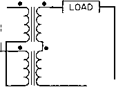 О A-c о SUPPLY D-C INPUT TO CONTROL WINDINGS о 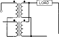 о A-c о SUPPLY (a) (b) Fig. 203. (a) Series and (b) parallel-connected simple magnetic amplifiers. is abrupt. If the loop were a true rectangle, the load current wave form would be as shown by Ъь in Fig. 204(a). Only the exciting current flows in the load during the interval 0-(9i. Then saturation is reached and load current suddenly rises to a large \aluc. From (9] to 7Г, 4 has sinusoidal shape. During the next half-cycle, this load current shape is repeated but in the reverse direction. For a 1:1 turns ratio in each reactor, current % in each control winding equals minus the exciting current. In one reactor, because of the reverse connection, current ic flows in the opposite direction. Total current in the control circuit is as shown by the lower trace of Fig. 204(a), the average value of which is the input direct current Ir-Thus load current contains fundamental and odd harmonics, whereas control current contains only even harmonics. If sufficient control current flows to saturate the cores over the full cycle, load current also flows over the full cycle and is sinusoidal in wave form. For turns ratios other than unity, load and control currents are inversely proportional to turns ratio. In the foregoing it was assumed that control current was free to assume the shape shown in Fig. 204(a). This is true, on a 1:1 turns-ratio basis only if the control circuit impedance is small. If total control circuit resistance is denoted by Rc and load resistance b Rl, for Ra Rl, load and control currents are sine waves, or portions thereof. If the opposite is true, namely Rc Rl, control current wave shape is determined by Rc- For very large Rc, control current is continuous, and the current wave shapes approach those in Fig. 204(6). In this figure, d-c source impedance is large, even harmonics cannot fiow, magnetization is constrained, load current is flat-topped, and voltage across the reactor is distorted considerably. This distortion can be overcome by the use of a capacitor across the control coils as n = 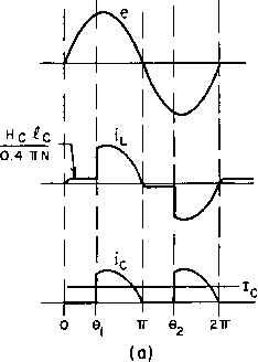 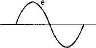 Fig. 204. Simple magnetic amplifier voltage and currents with (a) Rfj<<:Rj, and (b) Rc Rl- shown dotted in Fig. 203(a). When the reactors are parallel-connected, as in Fig. 203(6), even harmonics may flow in the load coils, and capacitors are unnecessary for Rc Rl- Sometimes the two cores are combined into one, in the manner shown in Fig. 205. This is called a three-legged reactor, with one d-c coil and two a-c coils. Figure 205 shows the relative paths for the a-c and d-c fluxes. Equal turns in the a-c coils set up equal a-c magnetomotive forces which cancel in the center leg, and cause fiux to flow as indicated by the solid line. No fundamental alternating voltage is induced in the d-c coil, but d-c flux flows in both outer les as indicated by the dotted lines. A change of current in the d-c coil causes a change in total flux linking the a-c coils and hence a change of inductance. A-c coils may be connected in parallel instead of series, provided that equal turns in each coil and the flux polarity of Fig. 205 are maintained; for the same total number of turns the in- 1 ... 23 24 25 26 27 28 29 ... 38 |
|
© 2026 AutoElektrix.ru
Частичное копирование материалов разрешено при условии активной ссылки |