 |
 |
 |
| Главная Журналы Популярное Audi - почему их так назвали? Как появилась марка Bmw? Откуда появился Lexus? Достижения и устремления Mercedes-Benz Первые модели Chevrolet Электромобиль Nissan Leaf |
Главная » Журналы » Transformer elementary form 1 ... 26 27 28 29 30 31 32 ... 38 Additional control windings are used for adding or subtracting input signals. This provides a simple means of combining several control functions in one magnetic amplifier. Response time in a self-saturated amplifier is longer than in a simple amplifier, but the gain per second is much greater. The time constant is Та = a,/2f (seconds) (123) where Та = time for 63 per cent response to step input a = amplifier voltage gain for 1:1 turns ratio = (AEl/AEc) X (Nc/Nl) for any turns ratio / = supply frequency AEl = change in load voltage AEc = change in control voltage Nc = turns in control winding Nl = turns in load winding. Equation 123 is valid for Та down to approximately 4 cycles minimum. Although smaller T may be obtained, it does not follow equation 123. Push-pull amplifiers are used to provide a-c or d-c output, with the output polarity dependent on input polarity. A d-c push-pull circuit which senses input polarity is shown in Fig. 220. Bias windings on each reactor carry current in such directions that amplifier outputs cancel for Ec = 0. For positive Ec, amplifier 1 produces positive E, and for negative Ec, amplifier 2 produces negative El. This circuit has low efficiency, owing to the power dissipated in the balance resistances Rl and Rz but has linear output. It is important, wherever two or more reactors are used together in magnetic amplifiers, that the reactors be alike in turns and in cores. Cores are generally selected to match, with closely duplicated B-H characteristics. It is not feasible to compensate core differences in balanced amplifiers by bias adjustments and still obtain linear output. 119. Half-Wave Control of Magnetic Amplifiers. Through attention to a-c voltages present in the control circuit, Dr. R. A. Ramcy analyzes magnetic amplifiers in a manner which gives rise to new circuits with desirable properties. A half-wave building block of such circuits is shown in Fig. 221 (a) for a 1:1 turns-ratio reactor. The load circuit is the same as in the half-wave amplifier of Fig. 214. The con- 1 See On the Mechanics of Magnetic Amplifier Operation and On the Control of Magnetic Amplifiers, by R. A. Ramny, Trans. AIEE, 70, 1214 and 2124, respecti\-ely. trol circuit comprises a-c voltage E and rectifier BXc in addition to variable rectified control voltage ec of polarity indicated. A-c voltage polarities are for the positive or conducting half-cycle in the load TO A-c SUPPLY 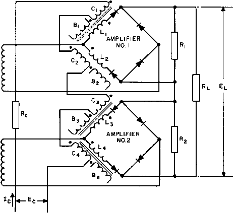 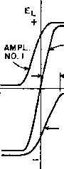 VOLTS ACROSS Rl WITH Rl R ANDR=R2 -BIAS ----NcIc AMPL. NO. 2 Fig. 220. D-c push-pull magnetic amplifier. circuit. During this half-cycle, RXc blocks and the control voltage is zero. During the next half-cycle, a-c line voltage E - ec appears across the reactor control coil. If ec is zero, the core is not magnetized by control current flowing during the positive half-cycle and 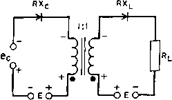 <i-oeo-+ f-o e o-H (a) (b) Fig. 22L Half-wave controlled magnetic amplifior.s. the core is completely reset by E during the negative half-cycle. If the peak value of ec is equal to л/2Е, it appears across the reactor in opposite phase to the line voltage and completely cancels it during the resetting half-cycle. This is shown dotted in Fig. 222, with both voltage waves designated by capital letters. This cancellation results in zero resetting; therefore full output current flows over 180° of the розШл^е half-cycle. If Ec = E/2 it subtracts from E, resulting in the lower dot-dash line of Fig. 222. The area under E ~ Ec (shown hatched) is just half of the area under E and therefore equals the hatched area under E during the interval 0 to тг/2 of the positive half-cycle. That is, the reactor absorbs voltage E during the interval 0 to 7г/2 and allows current to flow from 7г/2 to 7Г. But this is half of full or maximum output. Thus the output current is: zero for £(7 = 0 }i max for Ec = E/2 max for Ec = E 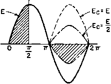 Fig. 222. Resetting voltages with half-wave control. Several advantages accrue from this type of control: 1. Output is proportional to control voltage. 2. Output depends only on control voltage and is independent of variations in line voltage or frequency. M-1 t- 3. Time of response is short (2 cycles or less). 4. Filtered d-c source of control power is not necessary. Proportionality of output to input voltage is strictly true only for zero control circuit resistance or zero reactor exciting current. The lower the control circuit resistance and reactor exciting current, the more nearly is output proportional to input. Rectangular B-H loop core material is necessary for linearity. Control circuit resistance can be made small without causing slow response in this circuit. Exciting current and control circuit resistance give rise to load Aoltage output with zero control Aoltage. Raising control voltage ec restores linearity of output. AVith half-wave control, voltage gain is more important than power gain; voltage gain is approximately equal to turns ratio. Mixing is not so readily accomplished in half-wave control circuits. Figure 221 (t ) shows how two half-wave sections are combined to form a full-wave bridge circuit with d-c output. This circuit differs from the circuit of Fig. 217(b) in that the control windings are isolated from each other by the control circuit rectifiers. Voltage E in the control circuit is an a-c bias voltage, and ec is rectified a-c signal voltage. Zero output voltage appears across E with вс - 0. When ec is increased, full-wave rectified voltage appears across Rl. The fundamental a-c component of this voltage is zero. 120. Magnetic Amplifier Design. Of first concern in design is the reactor core material. Supermalloy or other high-percentage nickel alloys are best suited as core material for the low power input stage. Grain-oriented nickel steel is used in the stages where output power is appreciable, and grain-oriented silicon steel where power is large. Figure 223 shows the d-c loops of two grain-oriented core materials, Hipersil and Orthonik. Although both materials have approximately rectangular B-H loops, the difference in rectangularity is marked. Grain-oriented nickel-steel strip such as Orthonik is usually wound into toroids, to insure that the flux flows in the preferred direction. The toroidal cores are protected from mechanical damage and strain by encasing them, as in Fig. 224, after the core material is annealed to ргевегл-е the magnetic properties. Grain-oriented silicon-steel cores are much less sensitive to damage; type С cores may be used, with coils wound as described in Chapter 2. In either type of core there is a small inevitable air gap. In a toroid, the flux must change from one lamination to the next as it flows around the core. If the insulating space between laminations is 0.0005 in. and the average core length is 5 in., the effective core gap le 16 14 12 10 < о о 5 в
.5 0 .5 1.0 L5 2.0 2.5 H-OERSTEOS Fig. 223. Typical d-c magnetization curves and hysteresis loops for 2-mil Hipersil and 2-mil Orthonik toroidal cores. 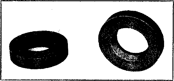 Fig. 224. Toroidal core of grain-oriented nickel steel in case, and with top of case removed. is 0.0005/5 = 0.0001 in. This gap is not negligible in high-permeability core material, but it is about one-tenth of the gap that manufacturers allow in type С cores. Effective core gap requires more control iV in. and reduces gain because the gap causes a more sloping B-H loop. Sec Fig. 242 (p. 310). Special U-shaped punchings of grain-oriented steel are sometimes used with alternate stacking to reduce the effective core gap. Another effect that reduces gain is rectifier back resistance, or current flow during the part of the negative half-cycle when inverse voltage exists across the diode. The peak value of inverse voltage divided by the corresponding reverse current is the rectifier back resistance. For a given peak source voltage \/2E, the inverse peak rectifier voltage is 2\/2E in the center-tap d-c circuit, and it \%\/2E in the bridge circuit, for zero winding and rectifier forward IR drops. In a doubler amplifier with zero forward drop, inverse peak voltage is zero, and increases with forward drop up to a maximum of \/2E. The reverse current corresponding to these voltages resets the core more than control circuit current with no rectifier reverse current. This causes transfer characteristic slope to decrease; the unity ordinate of the normalized transfer curve is displaced to the right by the ratio of reverse current to cut-off control current Ic- Normal cut-off control current Ic and cut-off output current /,v are not affected, because Ic operates to reduce load current during the positive half-cycle. Good-quality rectifiers are as important as good core material. This applies equally well to leakage current and forward current IR drop. Losses may limit output in rectifiers as well as in reactors. Most of the PR loss in windings of self-saturated amplifiers is usually in the load windings. This loss occurs during the part of the cycle in which load current flows, or while the core is saturated and core loss is zero. PR loss is a maximum when = 0 in Fig. 214(b). When 6 = 180°, PR. loss is negligible and core loss is a maximum. When the supply frequency is high, choice of rectifiers is limited to those with good high-frequency properties. At radio frequencies this may mean that suitable rectifiers are not available; simple magnetic amplifiers must then be used. To reduce core loss at high frequencies, ferrites are used. Insulation of toroidal coils is difficult to apply. Insulation between concentric windings is taped in and out like the wire. If voltage is low, the wire enamel is sufficient insulation. For 115- or 230-volt circuits, windings are laid on the core progressively, that is, with turns bunched di = VFT4AJt) (125) Coil axial length = Core case height + 2Au,/lc (126) Mean turn of first winding = Case periphery + tAi/Ic (127) where Au,i is area occupied by first winding. Equation 127 is approximate because wire turns tend to become circular after several layers are wound on the core. Example. Control Reactors for Single-Phase Rectifier. Assume the following conditions: Power supply 400 cycles. Center-tap d-c circuit per Fig. 217(c). Control current available = 40 ma d-c. Plate transformer E = 125 volts per side. so that adjacent turns have but a small a-c voltage difference. Insulation difficulties increase with voltage, and high-voltage reactors are preferably layer wound, with type С or stacked cores. Induced voltage in control windings requires careful attention, especially wdien control current is limited and many control turns are required. Although fundamental a-c voltage cancels in the control circuit, the full magnitude of this voltage is induced in the control windings. In the example of simple magnetic amplifier given in Section 111, the voltage induced in the control windings is 2,500/65 X 100 = 3,850 volts. With layer-wound coils and solventless resin coil impregnation the insulation is readily provided, but it would be difficult with toroidal coils. Winding space in a toroid is limited by the minhnura practicable hole size in the finished coil. This varies with the kind of winding machine and also with the size of toroid. If di = hole diameter d2 = core case inside diameter c?3 = core case outside diameter = total winding area, then A = (7г/4)№^ ~di) (124) On the outside of the toroid, the winding builds to a smaller height than on the inside. Since A is fixed by the minimum hole size, the coil outside diameter is di = d? - (4А^/7г) = л/(1-25)2 - (4 X 0.48/7Г) - 0.975 in. Ac turns occupy but a single layer. Then, for Nc, di 0.955 - 2(0.0064) = 0.94 in. With 10-mil insulation over Nc, the hole diameter becomes 0.94 - 0.02 = 0.92 in. Space required to insulate the ends of the windings and space for additional control windings reduce the hole diameter further. Winding mean turn lengths are, for a core-case periphery of 1.88 in., 1.88+-->-- = 2.16 in. 0.5 MTc = 2.16 + тг([0.48/5.51 + 0.О0Й4 + 0.020) = 2.44 in. D . .1 1 г 244 X 2.16 X 10.3 . Resistance oi loud wmdmg ---ToTinn--- olims T> . f . 1 - 276 X 2.44 X 338 . Rssistance of control winding =----ionnn---- ohms At full output Idc = 2 amp in Rl- Per cent reduction in Ec - 33 per cent at minimum output. Assume grain-oriented nickel-steel core with Ac ~ 0.1 sq in., Ic - 5.5 in., and Bs = 14,700 gauss. Core-case dimensions l}4 in. I.D., 2h( in. O.D., in. high. Each reactor must be capable of absorbing the voltage-tirae integral corresponding to 33 per cent voltage reduction, or 0.33 X 125 = 41 volts. From equation 34 (p. 83), 3.49X41X10 -I6oxl)TxT4770o = With full output, load winding current = 2т/(2 X 2) = 1.57 amp rms. From Fig. 219(a) this can be controlled with H - 0.5 oersted 0.5 = 0Шс1с/1с Nc = Ic/lc = 5.5/0.04 - 138 turns This will be increased to 276 turns to allow for rectifier reverse current, variations in slope of the core B-H loop, and effective core gap. Using 650 cir mils per ampere, and single enameled wire, yields 1.57 X 650 = 1,020 cir mils or No. 20 wire for Nl, and 0.040 X 650 = 26 cir mils or No. 35 wire for Nc- With an average winding area space factor of 60 per cent, the coil winding areas required are, from Table V (p. 37), 244/(860 X 0.60) = 0.48 in. for Nl and 276/(24,500 X 0.60) = 0.019 in. for Nc. If Nc turns are wound concentrically over Nl, the load winding inside diameter is, from equation 124, X [1 - (0.67)] = 0.0305-= 41 X 276 Time constant = ----------- = 0.07 sec 1.11 X 0.76 X 244 X 800 with no external series resistance in the control circuit. With feedback applied to the control winding, this rectifier can be made self-regulating. If the feedback is further refined by comparison with a voltage reference, a stable voltage regulator results. 121. Magnetic-Amplifier Limitations. Several limitations may affect the practical usefulness of magnetic amplifiers. Some of these limitations are beneficial in certain applications: 1. Residual output with zero input. 2. When more than one reactor is used in a circuit, reactor cores must often be matched. 3. Zero drift. At low input levels (of the order of 10 watt for toroids of rectangular loop core material) magnetic amplifiers do not track because of hysteresis. 4. Amplifiers with feedback or high-gain self-saturated amplifiers are subject to instability when biased to cut-off and may change linear amplifiers into bistable amplifiers. 5. When the amplifier operates over a wide range of ambient temperature, variations in resistance of the reactors and rectifiers, and hysteresis loop width, cause changes in gain, output, and balance. 6. Response time of a magnetic amplifier is a limitation in comparison with an electronic amplifier. 7. Variations in supply frequency and voltage cause Aariations in gain and output, especially with self-saturated amplifiers. 8. Whereas the vacuum tube is a relatively high-impedance device, the magnetic amplifier is better adapted to low impedances, where the turns arc fewer. 9. Saturation inductance is greater than the leakage inductance of the reactor, measured as in a transformer. The B-H curve slope at Bg, even with rectangular loop core materials, always gives /л greater than unity at the top. This effect reduces output and gain, and causes a sloping wave front at the instant of firing. Load winding /Й = 0.71 volt. PR = 1Л2 watt. Control winding IR = 0.76 volt. PR = 0.0305 watt. Many ingenious circuits have been devised to overcome one or more of these limitations. For descriptions of these circuits, for refinements of operation, and for fields of application, the reader is referred to the bibliography on magnetic amplifiers. 1 ... 26 27 28 29 30 31 32 ... 38 |
|||||||||||||||||||||||||||||||||||||||||||||||||||||||||||||||||||||||||||||||||||||||||||||||||||||||||||||||||||||||||||||||||||||||||||||||||||||||||||||||||||||||||||||||||||||||||||||||||||||||||||||||||||||||||||||||||||||||||||||||||||||||||||||||||||||||||||||||||||||||||||
|
© 2026 AutoElektrix.ru
Частичное копирование материалов разрешено при условии активной ссылки |