 |
 |
 |
| Главная Журналы Популярное Audi - почему их так назвали? Как появилась марка Bmw? Откуда появился Lexus? Достижения и устремления Mercedes-Benz Первые модели Chevrolet Электромобиль Nissan Leaf |
Главная » Журналы » Transformer elementary form 1 2 3 4 5 6 ... 38   Fig. 17. Fully enclosed transformers. The degree of enclosure depends on many conditions, among them the following: (a) Climate. In a humid climate, especially in the tropics, copper corrodes readily. Transformers containing fine wire may have open circuits soon after exposure to tropical conditions, and it is preferable to seal them against the entry of moisture. (b) Temperature Rise. Transformers handling large amounts of power may become hot because of the electrical losses. To seal them in containers imposes additional obstacles to the dissipation of this heat. Fortunately the wire size is large enough to withstand corrosion without developing open circuits. Such units may be of the open type. (c) Space. Sealing a transformer usually requires more space than mounting the core and coil directly on the chassis or panel. End cases like those in Fig. 16 do not require much space but do reduce cooling by convection. When air is used to cool other apparatus, power tubes for instance, it is very often circulated near or through the transformer to prevent the coils from overheating. (d) Voltage, In high-voltage dry-type transformers, enclosure in a metal case may add to the difficulties of insulating the windings. In oil-filled transformers, a tank is required for the oil and enclosure is thereby provided. 14. Mountings. Both types of cores may be built into neat assem-bhes with the laminations exposed, and the coils covered by end cases, such as those in the amplifier of Fig. 16. When complete enclosure is desired, assemblies like those in Fig. 17 are used. (e) Appearance. Generally speaking, enclosed transformers are neater than the open type. This fact is given consideration where space is available, especially in broadcast apparatus. 15. Core Materials. Electronic transformers make use of a large variety of core materials. In this chapter, the more useful magnetic properties of several grades of core materials are presented for reference and comparison. To guard against possible ambiguity, definitions of magnetic terms are first reviewed. Referring to the typical hysteresis loop of Fig. 18, curve OBm is the manner in which completely unmagnetized steel becomes magnetized by a magnetizing force H gradually increasing up to value Hm-Flux density or induction is not proportional to H but rises more gradually as it approaches Hm, Вщ. Once the material reaches this state, it does not retrace curve OB if H is reduced. Instead, it follows the left side of the solid-line loop in the direction of the arrow until, with negative Нщ, it reaches the maximum negative induction ~Bm. If H is now reversed, the induction increases as indicated by the right side of the loop, which is symmetrical in that the upper and lower halves are equal in area and have the same shape. In laboratory tests of magnetic material, the changes in Я are made slowly by means of a permeameter. The solid curve of Fig. 18 is then called the d-c hysteresis loop. If the changes are made more rapidly, for example at a 60-cycle rate, the loop is wider, as shown by the dotted lines. If a higher frequency is used, the loop becomes still wider, as shown by the dot-dash lines. At any frequency, energy is expended in changing induction from B to -B and back to Вт] this energy is called the hysteresis loss and is proportional to the area of the B-H loop. Increase in loop width with frequency is usually attributed to eddy currents which flow, even in laminated cores, to some degree. If a closed magnetic core is magnetized to induction Вщ and then the magnetizing force completely removed, induction decreases to residual induction Br and remains at this value in the absence of magnetizing force, or for Я = 0. The value of Я required to reduce В to zero is called the coercive force (He). From Fig. 18 it is evident that Br and He may change with frequency for the same Вш and grade of core material, and the design of transformers and reactors may be affected by the influence of frequency on core steel properties. According to equation 10, p. 12, the core flux is proportional to effective alternating \ltage for a given frequency and number of turns, and so is flux densit in a given core. Therefore the largest loop of   Fig. 18. A-c and d-c hysteresis loops. Fig. 19. Normal induction. Fig. 19 corresponds to a definite effective voltage and frequency, applied across a coil linking a definite core, and magnetizing it to maximum flux density Вт. If effective voltage is reduced 20 per cent a smaller B-H loop results, with lower maximum flux density Bm- If effective voltage is reduced further, still lower maximum flux density is reached. The locus of points Вщ, B\, B, etc., is drawn in Fig. 19, and is called the normal induction curve. It is similar in shape to, but not identical with, the virgin curve OB of Fig. 18. Each time the maximum flux density is lowered, a short time elapses before the new loop is traced each cycle. Thus the loops of Fig. 19 represent symmetrical steady-state or cyclic magnetization at different levels of maximum induction. A normal induction curve is drawn in Fig. 20. The ratio of В to Я at any point on the curve is the normal permeability for that value of B. For the maximum flux density B, the normal permeability is (19) It is the slope of a straight line drawn through the origin and B. A similar line drawn tangent to the curve at its knee is called the maximum permeability and is the ratio = B/W. The slope Bq/Hq of normal induction at the origin (enlarged in Fig. 20) is the permeability for very low induction Bq] it is called initial permeability and is usually much less than fx>n. Maximum permeability as here defined is really the average slope of the normal induction curve up to induction B\ Actual slope from  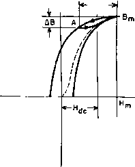 Fig. 20. Normal permeabilities. Fig. 2L Incremental permeability. О to B is greater at some points than maximum permeabiUty, because the curve is steepest below B. The slope at any induction is called differential permeability. From inspection of Fig. 19 it will be noticed that, for Я = 0, the sides of the B-H loop are steeper than any part of the normal induction curve and hence the slopes exceed /л^. This fact has practical significance in the design of magnetic amplifiers. In the foregoing, symmetrical magnetization has been assumed. If a core is magnetized with d-c magnetizing force Hc as in Fig. 21, and a-c magnetization ДЯ is superimposed, the cycfic magnetization follows a minor loop AB,n- Decreasing induction follows the left side of a major loop whose maximum induction is B., down to induction A - Вт - a5. Increasing induction follows a line which joins the right side of the major loop. The area of this loop is small, but so is the average slope, or incremental permeability. This permeability is important in reactor design. It is defined by 111, = LB/tH (20) and is generally smaller than /л^. The dotted line in Fig. 21 is the normal induction curve, the locus of the tops of minor loops as Hc is decreased. Returning now to Fig. 19, if Я^ is increased, an induction is finally reached at which unit increase of Я produces only unit increase in Вт-This is known as saturation induction B. The value of Я at which Bs is first reached is very large compared to H for most core materials. -Д H- A striking development has been the production of core materials with rectangular hysteresis loops. In such materials Bg is reached at small values of H, as shown in Fig. 22. Core material having a rectangular hysteresis loop is especially useful in magnetic amplifiers, and is discussed in Chapter 9. The volt-amperes per pound or apparent core loss (Pa) of a magnetic material is the product of rms induced voltage and rms exciting current drawn from the source when a pound of the material is subjected to sinusoidally varying induction of a specified maximum value B and of a specified frequency /. Exciting current is non-sinusoidal, as can be seen from Fig. 5, Chapter 1. The power component of Pa is the core loss Pc. The reactive component is usually the larger and is called VARS per pound. It is related to permeability in the following way: Let it be assumed that for conditions Вт, in a core the magnetizing current is approximately sinusoidal, of effective value Im, drawn from a supply of frequency / and effective voltage E. If we combine Fig. 22. Rectangular hysteresis loop. 1. Open-circuit inductance = Е/2-11 м BmAcN 2. Magnetizing force Hm = EImV л/2 Im X 10 QAttNImV- 3. VARS/lb = Aclc convert to inches, and put density p = 0.27 lb/in., then 152/Б„ (21) (22) (23) (24 7? 2 I J-m VARS/lb X 10* Because of the non-linearity of Im, this At 60 cyclee, = gj . equation is approximate. Moreover, there is no allowance for core gap. In usual electronic transformer practice, it is necessary to avoid reaching saturation flux densities, because high exciting currents ro-  0x11 0.1 1.0 Fig. 23. Core loss at high induction. Armco Trancor M15 grade, 29 gage. and with core losses ranging from 0.6 to 1.2 watts per pound at 10,000 gauss, 60 cycles {64,500 lines per square inch). Figures 23 and 24 are core-loss and exciting va/lb for a widely used grade of electronic transformer core steel at 60 cycles. Much work has been done in developing grain-oriented core materials. These materials have a composition similar to that of older, non-oriented core material, but grains in the material are oriented by cold-rolling in the direction illustrated by Fig. 25. Magnified sections of laminations are shown in this figure; (a) shows the random directions of easy magnetization in grains of non-oriented silicon steel. When magnetic flux is established in the lamination, the grains must be aligned in the same direction, as in Fig. 25(5). If the grains are already oriented in this direction during the rolling process, much duce high winding IB drops, high losses, low efficiency, and large size. Curves of induction and core loss are available from manufacturers of laminations. Grades and thickness are designated by numbers such as Armco Trancor M15 and Allegheny Transformer A. A wide choice of sihcon-steel laminations is available in 0.014-in., 0.019-in., and 0.025-in. thicknesses, with silicon content of approximately 3 to 4%, smaller magnetizing force is required to produce the desired flux. Coercive force and hysteresis loss are smaller than in non-oriented steel; permeability is greater, and so is Br, so that the rectangular loop of Fig. 22 is approached in grain-oriented steel. TESTS MADE ON EPSTEIN SAMPLES, AS SHEARED ----SAMPLE CUT PARALLEL TO ROLLING DIRECTION SAMPLE CUT HALF PARALLEL, HALF TRANSVERSE NEGLIGIBLE JOINT EFFECTS L- 60 CYCLES 1.0 Ю EXCITING R.M.S. VOLT-AMPERES PER, POUND Fig. 24. Exciting rms volt-amperes per pound, Armco Trancor M15 grade, 29 gage. Grain-oriented core materials are of two major types: silicon-steel and nickel-iron alloy. Electronic power transformers (i.e., plate and filament supply transformers) formerly comprised only hot-rolled silicon-steel cores. The development of grain-oriented silicon steel has had a marked effect on size and performance of such transformers. To STEEL ROLLED IN THIS DIRECTION  Fig. 25 CO Ш СЛ СД Z) <
MAGNETIZING FORCE-OERSTEDS FLUX DENSITY-KILOGAUSSES Fig. 26. Induction and core-loss curves of silicon steel and Hipersil at 60 cycles. The material is rolled in three major thicknesses: No. 29 gage (about 12 to 14 mils thick) for frequencies up to 400 cycles. 5 mils thick for frequencies 400 cycles and higher. 2 mils thick for frequencies in the low and medium r-f bands. Probably the most remarkable property of this material is its high saturation point. In Fig. 26 the comparison is given in terms of a hypothetical 60-cycle working induction using high-grade, conventional silicon steel. If this value is assumed to be 100 per cent, the induction obtained with grain-oriented steel is 130 to 150 per cent, with no increase in magnetizing force. Another way of expressing this improvement is shown in Fig. 27 as a comparison of the permeability of the two steels. The permeability of grain-oriented steel is much higher at the maximum point, and has the same percentage increase as in Fig. 26 for normal working inductions. Iron loss in Hipersil is less than in silicon steel, as Fig. 26 shows. The decrease in iron loss is chiefly due to a reduction in hysteresis loss; the eddy-current loss is less affected by grain orientation. Future comparisons may widen these differences. illustrate this effect, a comparison is made below between the older non-oriented steel (termed, for simplicity, silicon steel) and Hipersil, a cold-rolled steel in which grain orientation is carried out to a high degree. If core flux flows in the grain-oriented direction, high core inductions may be realized. Type С cores fulfill this requirement, because the strip is wound in the same direction as the flux path. The increase in induction is beneficial in several ways. First, it permits a reduction of core area for the same magnetizing current. Second, it results in a smaller mean length of turn and thus in a reduction in the amount of copper needed. In distribution and power transformers, for maximum benefit the iron and copper losses are repropor-tioned. In small electronic transformers, the iron loss is usually a small part of the total loss, and the reduction in copper loss is of greater significance. Within certain limits, the sum of the two losses determines the size of a transformer, and here the usefulness of grain-oriented steel becomes most apparent. H 40 J OD < cc ш a. Ф
100 1,000 MAXIMUM ALTERNATING FLUX DENSITY 6 IN GAUSSES 10.000 20.000 Fig. 27. Permeability of silicon and grain-oriented silicon steel The foregoing was written with 60-cycle applications particularly in mind. At higher power supply frequencies, such as the 400- and 800-cycle supplies encountered in aircraft and portable equipment, the results are somewhat different. The decrease in iron loss is not so marked, because the eddy current loss forms a larger proportion of the total iron loss. However, it is usual practice to use thin-gage laminations at these frequencies, and much better space factor can be obtained in wound cores than in stacked cores. The increase in permeability is just as effective in these higher frequency applications as at 60 cycles. The net result is a smaller transformer than was formerly possible, though for different reasons and in different proportions. Reactors which carry direct current are usually smaller when made with grain-oriented than with ordinary silicon steel. At low voltages, where low inductions are involved, grain-oriented steel has greater incremental permeability, and maintains it at high flux densities also. Consequently, a reduction of 50 per cent in weight is often feasible. Grain-oriented silicon steel does not replace high nickel-iron alloys for audio transformers, when they work at low inductions, and with little or no direct current. Some nickel-iron alloys have higher permea- -POWER 0-9Г AUDIO C-97 POWER Ю-Э5 FREQUENCY IN CYCLES -RF C-91 -> 10 10 lO 10* i06 10* Fig. 28. Use of Hipersil in various frequency zones. Hipersil can be used for transformers in various applications in the low and medium r-f bands, at power levels ranging up to hundreds of kilowatts. The same is true of video and pulse transformers, which may be regarded as covering an extended frequency range down into the audio range and up into the medium r-f range. Such transformers are grouped rather loosely together as r-f transformers in the diagram shown in Fig. 28. In this figure the several classifications, r-f, audio, and power transformers, are shown with respect to their frequency ranges and the approximate gage of the material used for these ranges. The gage is indicated by the symbol number in Table II. Table II. Hipersil Core Data Hipersil C-97 C-95 C-91 Thickness 0.013 in. 0.005 in. 0.002 in. Typical Hipersil Space Factor * 95% 90% 85% Typical Space Factor for Silicon Steel * 90% 80% 70% * Refers to percentage of core volume occupied by metal. The Hipersil figure is for type С cores, and the silicon steel figure is for punched laminations. Core-loss and exciting va/lb for 29-gage Hipersil are plotted in Figs. 29 and 30. Joint reluctance is neglected in Fig. 30. An example of specialized core materials is the development of a new grain-oriented silicon steel especially for weight reduction in com- bility at low flux densities, and their use for this purpose continues. But at high inductions, or where considerable amounts of direct current are involved, grain-oriented silicon steel is used. Lower distortion, extended frequency range, or small size is the result, and sometimes a combination of all three occurs. 1 2 3 4 5 6 ... 38 |
|||||||||||||||||||||||||||||||||||||||||||||||||||||||||||||||||||||||||||||||||||||||||||||||||||||||||||||||||||||||||||||||||||||||||||||||||||||||||||||||||||||||||||||||||||||||||||||||||||||||||||||||||||||||||||||||||||||||||||||||||||||||||||||||||||||||||||||||||||||||||||||||||||||||||||||||||||||||||||||||||||||||||||||||||||||||||||||||||||||||||||||||||||||||||||||||||||||||||||||||||||||||||||||||||||||||||||||||||||||||||||||||||||||||||||
|
© 2026 AutoElektrix.ru
Частичное копирование материалов разрешено при условии активной ссылки |