 |
 |
 |
| Главная Журналы Популярное Audi - почему их так назвали? Как появилась марка Bmw? Откуда появился Lexus? Достижения и устремления Mercedes-Benz Первые модели Chevrolet Электромобиль Nissan Leaf |
Главная » Журналы » Transformer elementary form 1 ... 28 29 30 31 32 33 34 ... 38 Vl,/Cd > 2Ri (132) Terms are defined in Fig. 235. The quantity у/Ь^Св regarded as the open-circuit imped- ance of the transformer. Its value must be more than twice the load resistance (on a 1; 1 ratio basis) to prevent oscillations after the trailing edge. This requires low distributed capacitance. Likewise the negative backswing may prove objectionable in certain apparatus. Certain conditions for aiiding ail backswing are those represented in Fig. 235 by /с = 5 and A = 0; these require good core material, low exciting current, low distributed capacitance, and a loaded transformer. 127. Total Response. By means of the curves луе can now construct the pulse shape delivered to load R. Suppose that a transformer with the following properties is required to deliver a flat top pulse of 15 microseconds duration. Primary leakage inductance (secondary short-circuited) = 1.89 X 10~ henry Primary open-circuit inductance =0.1 henry Primary/secondary turns ratio Vp/.Vg = 1:3 Source resistance R\ = 800 ohms Load resistance (primary equivalent) R2 = 5,000 ohms Primary effective capacitance C2 = 448 fijii From the expressions given in Fig. 230 m = 2.34 X 10 7 = 1.8 microseconds ki = 0.68 tion to the transformer, as will be explained later. For linear resistive loads, the terms are interchangeable with l and of Fig. 233, and with C2 of Fig. 229, all referred to the primary winding. In transformers with oscillatory constants the backswing becomes positive again on the first oscillation. In some applications this would appear as a false and undesirable indication of another pulse. The conditions for no oscillations arc all included in the real values of the equivalent circuit angular frequency, i.e., by the inequality 4:RiCr) LeCf) The front of the wave follows a curve betAveen those marked ki = 0.4 and /ci = 0.8 in Fig. 230. Value Ea is reached in 0.57 or 0.85 microsecond, and an overshoot of about 10 per cent occurs in 1.2 microseconds. The top of the wave slopes down to a voltage determined by the product rRx/Le = 0.12, and by a curve between those for Я-, - x and i?2 = 21 in Fig. 234. Voltage E at Ъ is evidently 0.9£/ . The trailing edge is found from Fig. 235. Here T = 42.2 X 10-* Vo. 1/448 X 10-2 2 X 5,000 = 1.5 5,800 800 X 0.09 = 0.65 Load voltage reaches zero in 0.05T or 2.11 microseconds. The negative loop has maximum amplitude of 33 per cent at 0.27 or 8.44 microseconds beyond the pulse edge 6. The pulse deliired to load i?2 is shown in Fig. 236, in terms of E instead of Ea. 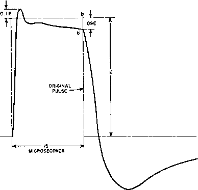 Fig. 236. Output voltage of pulse transformer. So far we have assumed that the pulse source is disconnected at the end of the pulse. In some applications the source remains connected. This would result if switch S (Fig. 233) were left closed, and battery E were short-circuited. Under these conditions the leakage inductance remains in the circuit, and an additional transient occurs. The transient has a shape similar to one of the curves of Fig. 231 but is inverted and superposed on the backswing voltage due to OCL. In the example just given, this superposed oscillation has an amplitude of 10 per cent of E, with a total result similar to the oscillogram of Fig. 237. Superposed backswing oscillations are discussed more fully in Section 134. Because of the distributed nature of leakage inductance and 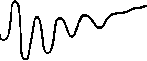 Fig. 237. Oscillogram of voltage pulse. capacitance, higher-frequency superposed oscillations may sometimes occur even when the load is disconnected at the end of a pulse. By their very nature, the conditions for these oscillations are difficult to state with certainty, but if oscillations occur on the front edge they are likely to appear on the trailing edge, superposed on the voltage back-swing. 128. Step-Down Transformers. The circuits of Figs. 229 and 233 for step-up pulse transformers arc essentially the same as those of Figs. 107(e) and 107(c), respectively, for audio transformers. Low-frequency response corresponds to the top of tiie pulse and high-frequency response to the front edge. In stcp-doлvn pulse transformers the top is unchanged, but the front edge corresponds to Fig. 113. Step-down transformer analysis shows that the form of equation is similar to that for step-up transformers, except that the damping factor for the sine term is greater by the quantity R2/L. Also, the decrement, although still composed of two terms, has the resistances R- and J?2 in these two terms reversed with respect to the corresponding terms for the step-up transformer. Except for this, the front-edge curves are little different in shape from those of step-up transformers. AVhere = ita the cunes are virtually the same as in Fig. 231. Pentode amplifiers, with their constant-current characteristics, can be represented by the circuit of Fig. 238. Here / is the current entering the primary winding from the tube, and is constant over most of the voltage range. The transformer is usually step-down for the reasons of impedance mentioned in Section 70 (Chapter 5). Front-edge response of the.se transformers is the same as in Fig. 230 if the rise in load current is expressed as a fraction of final current I, and the decrement is changed to R2/2Ls. It is reproduced in Fig. 239 with this change in constants. Flatness of top is approximately that of the curve R2 = 0.1i?i in Fig. 234. Trailing edge is the same as in Fig. 235. Fig. 238. Step-down transformer equivalent circuit. It is evident that many practical cases are represented by the figures. If transformer constants are outside the curve values, the pertinent equation should be plotted to obtain the response. 129. Frequency Response and Wave Shape. Because of the prevalent thinking of engineers in terms of frequency response rather than wave shape, it is sometimes necessary to correlate the two concepts. The matter of phase shift enters, for the reason that the relative phase of the different frequency components affects wave shape. It is sometimes convenient to know whether a transformer, whose frequency response is known, can deliver a given wave shape. Starting with the low-frequency response, assume equal source and load resistances; the upper curve of Fig. 108 (p. 148) applies. This curve shows 90 per cent of maximum response at the frequency for which Xt/R = 1. How does this frequency compare with the reciprocal of the pulse width at the end of which there is 10 per cent droop in the top of the pulse? Xi/R can be written 2jrfL/Ri - 1 or / = /i/27r7. (133) Likewise, from the proper curve of Fig. 234, for 10 per cent droop, tRi/L = 0.2 (134) Combining equations 133 and 134 gives / = 0.0318 (1/т), or the transformer should be not over 1 db down at a frequency about of the reciprocal of the pulse width. For example, if a maximum of 10 per cent droop is desired at 2 microseconds the response should be not 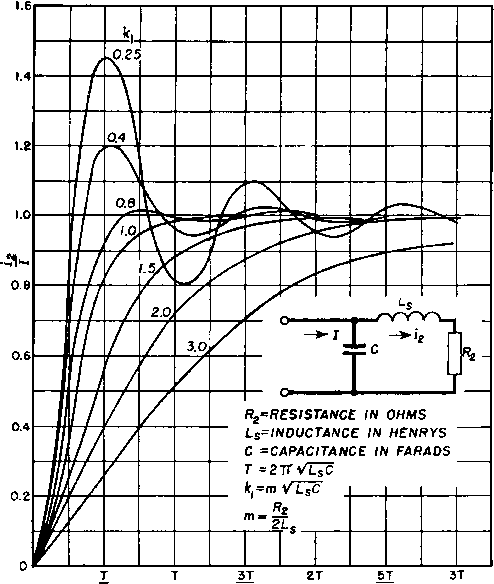 г г г Fig. 239. Pentode amplifier front-edge response. more than -1 db at 0.0318 X 0.5 X Ю* 16 kc. Maximum phase shift is 27 degrees (from Fig. 131, p. 180), but this is taken into account in Fig. 234. Similarly, front-edge steepness can be related to transformer high-frequency response, which for the case of Ri = R2 is found in Fig. 109. The corresponding front-edge curves are found in Fig. 231. Parameter ki of these curves is related to В in Fig. 109 as follows. h = rnVbC =--h -- (for Rl = R2) 2L 2RiC в = - = - at frequency fr Rl Rl 2-KfrL L Rl RiVlC 1 в + - (135) From equation 135 we can prepare Table XVI. Table XVI. Parameters for Frequency Response and Wave Shape 1.0 1.0 0.8, 1.25 1.025 0.67, 1.5 1.08 0.5, 2 1.25 0.25, 4 2.125 If a transformer has frequency response according to the curve for в = 2 in Fig. 109, its front edge will rise somewhere between curves for /ci = 1 and /ci = 1.4 in Fig. 231. Transformer ocl, leakage inductance, and effective capacitance must be known to make this comparison, but these quantities are already known if it is established that the frequency response is given by Figs. 108 and 109, or the wave shape by Figs. 231 and 234. If conditions other than Ri = R2 prevail, another set of response curves can be used, and corresponding approximate relations can be found in the manner here outlined. Pulse transformer windings are similar to those in the high-frequency transformers described in Section 87 (Chapter 7). Resonance frequency fr is determined largely by leakage inductance and winding-to-winding capacitance. With pulse operation, partial resonances of sections of a coil, and even turn-to-turn resonance, may appear because of the steep front edge of voltage impressed on the transformer. If these resonances cause pronounced oscillations in the output wave form, larger coil or turn spacings or fewer turns may be necessary to reduce them. 130, Core MateriaL In Chapter 7 it was shown that core permeability decreases with frequency, especially at frequencies higher than audio. This decrease also occurs with short pulse widths. When a pulse is first applied to the transformer, there is initially very little penetration of flux into the core laminations because of eddy currents. Hence initially only a fraction of the total core is effective, and the apparent permeability is less than later in the pulse, or after the flux density becomes uniform throughout the laminations. A typical B-H curve for pulse transformers is shown in Fig. 240. Flux density builds up in the core in the direction shown by the arrows.
MAGNETIZING FORCE H Fig. 240. Pulso В-П loops. For a typical loop such as obcd, the slope of the loop (and hence the permeability) rises gradually to the end of the pulse Ъ which corresponds to point b in Fig. 236. Since magnetizing current starts decreasing at this point, H also starts decreasing. Cvirrent in the windings does not decay to zero immediately but persists because of winding capacitance, and sufficient time elapses for permeability to increase. Therefore, flux density В may also increase during a short interval after point h. The trailing edge of the pulse voltage soon reaches zero, and this corresponds to point с on the loop. At some interval later, the maximum backswing amplitude is reached, which corresponds to point d on the loop. At this point the slope or permeability is several times as great as at point b. For any number of pulses of varying amplitudes but of the same width, there are corresponding loops having respective amplitudes c. A curve drawn through point b of each loop is called the normal permeability curve, and this is ordinarily given as the permeability curve for the material. The permeability ix for a short pulse width is less than the 60-cycle or d-c permeability for the same material. Values of pulse permeability for 2-mil grain-oriented steel are given in Fig. 24L The permeability values include the irreducible small gap which exists in type С cores; the cores on which the measurements were made had a ratio of gap to core length Ig/lc 0.0003, but the data are not criti- Г1400 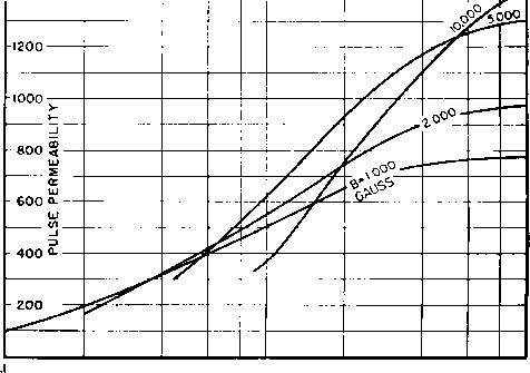 .4 .6 ,8 ю г pulse width in microseconds e 10 Fig. 241. Effective permeability versus pulse width. cally dependent on this ratio. The effect of penetration time is clear. Flux densities attained in pulse transformers may be low for small units where very little source power is available, or they may be high (several thousand gauss) in high power units. This is true whether the pulse width is a few microseconds or 1,000 microseconds. The nickel-iron alloys in general have lower saturation densities, but higher permeabilities below saturation than either grain-oriented or ordinary silicon steel. Depending on the flux density chosen, the increase of permeability with the use of a nickel-iron alloy may vary from zero to 300 per cent. This increase holds also for long-time pulses, during which permeability may approach the 60-cycle value. In order to overcome the net d-c pulse magnetization which is in the same direction throughout each pulse, an air gap may be inserted in the core to prevent it from returning only to the residual magnetism value Br at the end of each pulse, and thereby limiting its useful pulse flux density range ДЛ to the difference between maximum flux density Bn and residual Br (see Fig. 242). This gap increases the effective length of the magnetic path and reduces OCL from the value it has лvith symmetrical magnetization. The reduction is less with core materials of low permeability. To maintain the advantage of high permeability in nickel-iron alloys, the core is reset. This is done by ДВ WITHOUT GAP OR RESETTING 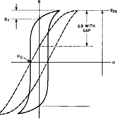 ДВ WITH RESETTING Fig. 242. Flux density range in pulse transformer cores. arranging the circuit so that, during the period of backswing, sufficient negative current flows through the windings to overcome coercive force He and drop the flux density to the negative value of residual magnetism. Then nearly twice the previous maximum flux density (ДБ in Fig. 242) is available for the pulse. Where resetting is possible, it is advantageous to use nickel-iron alloys; where resetting is not racticable, grain-oriented silicon steel is preferable. 131. Windings and Insulation. Pulse transformers generally have single-layer concentric windings with solid insulation between sections. For high load impedance, a single section each for primary and secondary as in Fig. 166 is favorable, as the effective capacitance is lowest. For low load impedance, more interleaving is used to reduce leakage inductance. To reduce capacitance to a minimum, pie-section со- axial windings may be used. In these, coil capacitance is kept low by the use of universal windings, and intersection capacitance between windings is low because the dielectric is air. Such coils are more difficult to wind, require more space, and therefore are used only when necessary. Coil sections can be wound with the same polarity as in Fig. 166 (p. 219) or with one winding reversed. Effective capacitance between F and S is given below for three turns ratios. Capacitance is. based on 100 fifii measurable capacitance. Turns Ratio Effective Capacitance Referred to Primary N\/N% Same Polarity Reversed Polarity 1:5 533 1200 1:1 0 133 5:1 21 48 From this it can be seen that the polarity exemplified in Fig. 166 is preferable for reducing effective capacitance, but that the percentage difference is greatest for turns ratios near unity and less as the ratio increases. Attention to the insulation so far has centered around capacitance. The insulation also must withstand the voltage stress to which it is subjected. It can be graded to reduce the space required. Low-frequency practice is adequate for both insulation thickness and end-turn clearances. Small size is achieved by the use of solventless varnish. Small size with consequent low capacitance and low loss results in higher practicable impedance values and shorter pulses. In order to utilize space as much as possible, or to reduce space for a given rating, core-type construction is often used. Low capacitance between high-voltage coils is possible in such designs. It is advantageous in reducing space to split the secondary winding into nonsymmetrical sections. Although the leakage inductance is higher with non-symmetrical windings, there is less distributed capacitance when the high-voltage winding has the smaller length. Lower capacitance obtains with two coils than with a shell-type transformer of the same interleaving. In core-type transformers high-voltage windings are the outer sections. It is preferable to locate terminals or leads in the coil directly over the windings in order to maintain margins. Insulating barriers may be located at the ends of the windings to increase creep-age paths. 1 ... 28 29 30 31 32 33 34 ... 38 |
|||||||||||||||||||||||||||||||||||||||||||||||||||||||||||||||||||||||||||||||||||||||||||||||||||||||||||||||||||||||||||||||||||||||||||||||||||||||||||||||||||||||||||||||||||||||||||||||||||||||||||||||||||||||||||||||||||||||||||||||||||||||||||||||||||||||||||||||||||||||||||||||||||||
|
© 2026 AutoElektrix.ru
Частичное копирование материалов разрешено при условии активной ссылки |