 |
 |
 |
| Главная Журналы Популярное Audi - почему их так назвали? Как появилась марка Bmw? Откуда появился Lexus? Достижения и устремления Mercedes-Benz Первые модели Chevrolet Электромобиль Nissan Leaf |
Главная » Журналы » Transformer elementary form 1 ... 30 31 32 33 34 35 36 ... 38 Total = 0.462 The no-load loss is [(2,000)V4001 X 1,000 X 2 X lO = 20 watts. Copper loss is therefore of little significance. From the coil dimensions and insulation thicknesses we can figure the capacitances. The total winding traverse for both coils is 1.875 in. The primary-to-core capacitance is 0.225 X 3.75 X 1.875 X 5 , ---= 264,Mt and the secondary-to-primary capacitance is 0.225 X 4.13 X 1.875 X 5 0.060 = 145 jujUi so that these two capacitances in series are 94 ju/zf. Secondary turn-to-turn capacitance is, approximately, 0.225 X 4.13 X 0.0126 X 3 , 0Ж9 = 0.184 a is therefore .184 = 22.5, and the wire enamel initially must withstand 2,250 volts per turn. Figure 246 is a photograph of the transformer with Fosterite-treated coils. 135. Testing Technique. Tests for open circuits, short circuits, turns ratio, and d-c resistance are made on pulse transformers in the same manner as in other transformers. The instruments used must be suitable for the low values of inductance encountered, but otherwise no special precautions are necessary. Usually the d-c resistance is somewhat lower than the winding resistance during most of the pulse, but even the latter value is so low that it causes no significant part of the transformer loss. Losses are measured as described in Section 132. Various methods have been used to check effective pulse OCL. These may involve substitution of known inductances, or current build-up, or decay, depending on the time constant of the transformer in the secondary and No. 22, wound two in parallel to occupy the form fully, in the primary. The core section is % in. by % in. The primary turn length is 3.75 in. and that of the secondary is 4.13 in. Primary and secondary d-c resistances are 0.05 and 2.3 ohms, and the respective copper losses are (1.8)2 0.05 = 0.162 (0.36)2 X 2.3 = 0.3 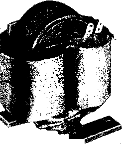 Fig. 246. Pulse transformer with coils of Fig. 245. purposely made large to reduce saturation, proper allowance for it can be made in equation 38 (p. 97). If the gap is the minimum obtainable, it is necessarily included in the permeability measurement, but this is often done in taking pulse permeability data, as it was in the data of Fig. 241. With this definition of permeability equation 38 reduces to OCL = (3.2/xA2 X 10~*) , (141) Equation 141 is valid only when lc/}x >>> Ig. B-H data for a pulse transformer are taken by means of a circuit similar to that of Fig. 247. Primary current flowing through small resistor i?i gives a horizontal deflection on the oscilloscope propor-ional to / and therefore H for a given core. should be low enough in ohmic value not to influence the magnetizing current wave form inductance and an external known resistance. When such measurements are attempted under pulse conditions, there is usually a certain amount of error due to reflections, incidental capacitance, and the like. A method involving the measurement of pulse permeability and calculation by the OCL formula is given here. If the air gap and pulse permeability are known, the OCL for a given core area and number of turns can be calculated. If the gap used is appreciably. If the voltage drop across a higli-resistance load R2 50 times normal pulse load) is almost the entire secondary \olt-age e-2, then voltage applied to the vertical plates is the time integral of 62 and is therefore proportional to flux den.ity at any instant. (Sec equation 138.) Short leads and the reduction of incidental capacitance arc essential to obtain accurate measurements. Distributed capacitance of tlie winding, shown dotted, should be minimized, as il introduces extranc- PULSE TRANSFORMER 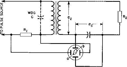 OSCILLOSCOPE Fig. 247. B~H test for pulse transformers. ous current into the measurement of H. One way to minimize this capacitance is to omit the high-voltage winding, and make all measurements from the low-voltage low-capacitance coil only. The pulse source should be the kind for which the transformer is to be used, If it must be loaded to obtain proper i)ulse shape, a diode may be used to prevent backswing discharge through this load and therefore a reset core, unless reset core data arc desired. Difficulty may be experienced in seeing the B-H loops of pulses having a low ratio of time on to time off because of the poor spot brilliance, unless an intensifier is used to brighten the trace. With a calibrated oscilloscope it is possible to det(Mmine the slope of the dotted line ob in Fig. 247, drawn between the origin and the end of the pulse, and representing effective permeability ц at instant b, Fig. 226. This value of /x can be inserted in equation 141 to find OCL. Cores failing to meet the OCL should first be examined for air gap. Effective values of leakage inductance and ca aeitance are difficult to measure. The calculations of capacitance and leakage inductance are based on the assumption of lumped values, the validity of which can be checked by observing the oscillations in an unloaded transformer when pulse voltage is applied. The frequency and amplitude of these oscillations should agree with those calculated from the leakage inductance and effective capacitance. The pulse source should be 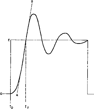 Fig. 248. Transformer constants may be found from pulse shape. chosen for the squareness of its output pulse. Because of the light load, the transformer usually will be oscillatory, and produce a secondary pulse shape of the kind shown in Fig. 248. In this figure, the dot-dash line is that of the impressed pulse and the solid curve is the resulting transformer output voltage. This curve is observed by connecting the vertical plates of a synchroscope (oscilloscope with synchronized sweep) across the transformer output winding. The first check of leakage Lg and Co is made by finding the time constant T from This time constant can be related to the time interval to-tr in Fig. With this value of fci, the increase or overshoot of the first voltage oscillation over the flat top value E may be found from Fig. 230, and may be compared with that observed in the test. When the load is resistive, or when the voltage pulse is the criterion of pulse shape, these are the only checks that need to be made on leakage inductance and distributed capacitance. When the load is a magnetron, triode, blocking oscillator, grid circuit, or other non-hnear load, the shape of the current pulse is important. Ordinarily the current will not build up appreciably before time tr in Fig. 248. The shape of this current pulse and sometimes the operation of the load are determined to a large extent by slope AB of the no-load voltage at time t,-. This time is the instant when the first oscillation crosses the horizontal line E in Fig. 248. As indicated in Fig. 244, there is a relationship between this slope and the parameter kt. If the slope AB is confirmed, correct current pulse shape is also assured. Insulation can be tested in one of two ways, depending on whether the insulation and margins are the same throughout the winding or whether the insulation is graded to suit the voltage. In the former case an equivalent 60-cycle peak voltage, applied from winding to ground at the regular 60-cycle insulation level, is sufficient. But, if the winding is graded, this cannot be done because the voltage must be applied across the winding and there is not sufficient OCL to support low-frequency induced voltage; hence a pulse voltage of greater than normal magnitude must be applied across the winding. Adequate margins support a voltage of the order of twice normal without insulation failure. Such pulse testing also stresses the windings as in regular operation, including the non-uniform distribution of voltage gradient throughout the winding. The higher-voltage test ought to be done at a shorter pulse width so that saturation does not set in. In cases of saturation. 248 by consulting Fig. 230. Formulas in this figure can be used for finding values of parameter fci using Ls, C2, source resistance and load resistance R2. This load resistance will be that corresponding to transformer losses only; hence R2 Ri for a pulse source with plenty of power, and the voltage backswing is likely to exceed the pulse voltage of normal polarity and thus subject the insulation to an excessive test. This backswing may be purposely used to obtain higher voltage than the equipment can provide, but it must be carefully controlled. Corona tests are sometimes used in place of insulation tests, and this can be done, where the insulation is not graded, by using a 60-cycle voltage and a sensitive receiver to pick up the corona noise. With graded 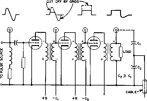 polarities + and - occur during pulse terminals 0 indicate pulse viewing connections oscilloscope Fig. 249. Pulse amplifier with oscilloscope connections. insulation a high frequency must be used. The method becomes too difficult to use because the receiver may pick up part of the high-frequency power emitted from the transmitter, or the transmitter parts may generate a certain amount of corona which is more troublesome than at 60 cycles. In pulse amplifiers, the mode of operation of the tubes and circuit elements is important. A round irregular pulse may be changed by grid saturation, or by non-linear loading of some other sort, into a practically square wave pulse. It may take several stages of amplification to do this in certain instances, and a transformer may be used at each stage. Often the function of the transformer is to invert the pulse for each stage; that is, the transformer changes it from a negative pulse at the plate of one stage to a positive pulse on the grid of the next. Polarit is therefore important and should be checked dur- ing the turns-ratio test. If the transformer fails to deliver the proper shape of pulse, it may be deficient in one of the properties for which tests are mentioned above. Figure 249 shows a ])ulse amplifier with normal pulse shapes for each stage. Checking each .stage at the points indicated, without spoiling the pulse shape by the measuring apparatus, requires attention to circuit impedance, stray capacitance, cable termination, and lead length. 11. PULSE CIRCUITS Pulse generation and utilization require the use of various non-sinusoidal devices. Formation of pulses from sine waves was mentioned briefly in Chapter 10. In the following sections, other methods of forming and using pulses are described. 136. Blocking Oscillators. Blocking oscillators are used to obtain pulses at certain repetition rates. The pulse may be used to drive a grid leak grid damping res. grid bias condenser grid winding
 oscillator tube Fig. 250. Blocking oscillator. pulse amplifler, or it may be used to modulate a VHF oscillator. A typical blocking oscillator circuit is shown in Fig. 250. The grid is dri\en hard, and grid current usually is comparable in magnitude to anode current. Grid and anode winding turns are approximately equal. The oscillator operates as follows. If the grid is only slightly negative, the tube draws plate current and because of the large number of grid turns the transformer drives the grid positive, increases the plate current, and starts a regenerative 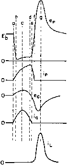 INSTANT a-PULSE STARTS. ANODE CURRENT RISES. INSTANT b-SUDDEN RISE IN ANODE CURRENT INDUCES ANODE WINDING VOLTAGE PEAK, PROBABLY AT SATURATION VALUE. INSTANT с-DUE TO COUPLING К < I, GRID VOLTAGE PEAKS LATER. GRID CURRENT PEAKS SIMULTANEOUSLY. INSTANT d-ANODE CURRENT MAXIMUM ANODE VOLTAGE STARTS TO FALL INSTANT e-GRlD VOLTAGE AND CURRENT ZERO INSTANT f-ANODE VOLTAGE AND CURRENT ZERO. INSTANT g-VOLTAGE BACKSWING REACHES PEAK. CAUSES PEAK LOAD CURRENT i. Fig. 251. Blocking oscillator voltages and niirents. reflected from the grid, and the charge accumulated on the bias capacitor becomes great enough to decrease plate current rapidly in a degenerative action. Plate current soon cuts off, and then the plate voltage overshoots to a high positive value and the grid voltage to a high negative value. Grid voltage decays slowly because of the discharge of the bias capacitor into the grid leak. The next pulse occurs when the negative grid voltage decreases sufficiently so that regenerative action starts again. Hence the repetition rate depends on the grid bias R and С Either the negative or the positiAe pulse voltamay be utilized. Instantaneous voltages and currents are shown in Fig. 251 for a load which operates only on the positive pulse. The geniMal shapes of these currents and voltages approximate those in a practical oscillator, except for superposed ripples and oscillations whicli often occur. The negative pulse has a much squarer wave shape than the positive action. During this period, the grid draws current, charging the bias capacitor to a voltage depending on the grid current flowing into the bias resistor-capacitor circuit. The negative plate voltage swing is determined by grid saturation, so that large positive swings of grid voltage result in virtually constant plate voltage. This continues for a length of time determined by the constants of the transformer, after which the regenerative action is reversed. Because of lowered plate voltage swing, the plate circuit can no longer dri e the low impedance pulse, and consequently it is used where good wave shape is required. No matter how hard the grid is driven, plate resistance cannot be lowered below a certain value; so a limit to the negative amplitude is formed. There is no such limit to the positive pulse, and this characteristic may be used for a voltage multiplier. If the transformer has low OCL, the leakage inductance may be high enough to perform like an air-core transformer. That is, there are optimum values of coupling for maximum power transfer, grid drive, and negative pulse shape, but they are not critical. Comparison of peak voltages in Fig. 251 shows that the usual 180° phase relationship between grid and plate swings do not hold for such a blocking oscillator, if the term phase has any meaning in this case. The front-edge slope of the negative pulse is determined by leakage inductance and capacitance as in Fig. 230, with two exceptions: the pulse is negative and the load is non-linear; hence there are no oscillations on the inverted top. The slope of this portion can be computed from Fig. 234, provided tube and load resistances are accurately known. The positive pulse can be found from Fig. 235 if these curves are inverted. Pulse width, shape, and amplitude also are affected by the ratio of grid turns to plate turns in the transformer. Voltage rise is steeper as this ratio is greater, with the qualification that grid capacitance increases as the square of the grid turns; the ratio is seldom greater than unity. The exact ratio for close control depends on tube data which may not be available and must be determined experimentally. The situation parallels that of the class С low-Q oscillators mentioned in Chapter 6. The circuit of Fig. 250 is called a free-running blocking oscillator. When it is desired to synchronize or otherwise control the pulse repetition rate, an external trigger pulse is applied to the blocking oscillator grid or cathode. 137. Line-Type Radar Pulsers. Figure 252 is the schematic diagram of a line-type pulser or modulator. This pulser is of the variety known as d-c resonant charging, with hold-off diode. The operation of the pulser is as follows: During the charging period of each cycle, the diode permits direct current to flow through the charging reactor to the pulse-forming network and through the primary of the pulse transformer to ground. The rate of charging is governed largely by the inductance of the charging reactor and pulse-forming network capacitance. The inductances in the pulse-forming network and the leakage inductance 1 ... 30 31 32 33 34 35 36 ... 38 |
||||||||||||||||
|
© 2026 AutoElektrix.ru
Частичное копирование материалов разрешено при условии активной ссылки |