 |
 |
 |
| Главная Журналы Популярное Audi - почему их так назвали? Как появилась марка Bmw? Откуда появился Lexus? Достижения и устремления Mercedes-Benz Первые модели Chevrolet Электромобиль Nissan Leaf |
Главная » Журналы » Transformer elementary form 1 ... 31 32 33 34 35 36 37 38 of the pulse transformer are so small as to be negligible during this period. The pulse transformer load is the magnetron, which is operated with high negative potential on the cathode. A d(шble winding is provided on the pulse transformer secondary to pcimit filament current to flow into the magnetron filament. The reactances of the pulse-forming network and the charging reactor at their resonant frequency are high compared to the circuit equivalent series resistance. Therefore, the pulse-forming network charges up to a voltage 2E, where E HOLD-OFF DIODE 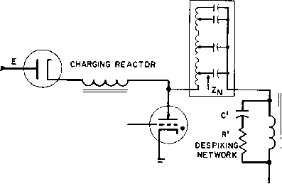 PULSE -FORMING NETWORK PULSE TRANSFORMER MAGNETRON HYDROGEN THYRATRON  FROM FILAMENT j- -L TRANSFORMER Fig. 252. Simphfied schematic of modultitor. is the d-c supply voltage. Negligibly small voltage appears on the pulse transformer and magnetron during the charging interval. After the pulse-forming network has charged up fully, it is prevented from discharging back through the d-c source by the hold-off diode. At some subsequent instant, a trigger voltage on the grid of the hydrogen thyratron causes the thyratron to conduct and permits the pulse-forming network to discharge through the very low internal resistance of the thyratron. The sudden discharge of current through the thyratron causes a voltage wave to start down the pulse-forming network as in Fig. 253. This voltage is an inverted step function with a value {2E - E) = E. Initial voltage 2E on this network is divided equally between the network and the pulse transformer primary, and produces pulse voltage E, of duration т. The pulse width r is the length of time that the pulse takes to travel down the pulse-forming network (PEN) and back. After time ti the circuit is ready to charge slowly again through the charging reactor. Magnetron current and voltage rise at the pulse leading edge in general accordance with the explanation of Section 133, but sometimes despiking network RC is included to reduce current oscillations. In this pulser, the magnetron equivalent resistance Rm (referred to the pulse transformer primary) is equal to Zf, the pulse-forming network impedance. t, t (a) VOLTAGE ON SENDING-END OF PULSE-FORMING NETWORK. (b) VOLTAGE ON PULSE- TRANSFORMER PRIMARY WINDING Fig. 253. Modulator voltages. If the magnetron circuit opens during pulser operation, voltage applied to the pulse transformer primary is doubled. This may cause insulation failure if the open circuit continues. For this reason, spark gaps are often provided on pulse transformers in line-type pulsers. 138. False Echoes after Main Pulse. Trailing-edge oscillations are of two general types: (1) a long-term or low-frequency oscillation (see Fig. 254) dependent on capacitance Co and pulse transformer open-circuit inductance Lg, and (2) a superposed high-frequency oscillation dependent on capacitance Cn and LV (= PFN inductance Lr plus pulse transformer leakage inductance Ls). If these oscillations exceed zero in the positive or main pulse direction, false echoes of two kinds may occur: close echoes, adjacent to the main pulse, and distant echoes which appear later at a comparatively longer time interval. Either of these cause the magnetron to give a false indication. The distant echo corresponds to oscillation (1), and the close echo superposed on this long-term backswing to oscillation (2). These are represented in Fig. 254 as oscillations /3 and /2, respectively. With proper attention to the circuit constants, it is possible to eliminate both types of echoes. The low-frequency backswing oscillation or axis is affected by Cn only while it is still in the circuit. When thyratron conduction ceases (soon after the trailing edge becomes negative) is cut out of the circuit. Once this happens, the presence or absence of distant echoes is determined only by Co in combination with Le and Re. More- over, if СцСв, close echoes are also determined by Cd and LV, regardless of whether or not the thyratron is conducting during the close-echo interval. Both low- and high-frequency oscillation amplitudes depend on the amount of resistance in the circuit. At instant U. this resistance is йл/, the magnetron resistance E/i2 (Fig. 243), in comparison with which the transformer core-loss equivalent resistance Re is negligibly high. After the magnetron ceases conducting, only remains. Dur- RISE TIME DEPENDS ON k, DISTANT ECHO OSCILLATION f. 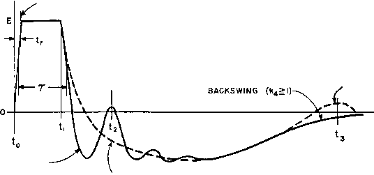 TIME-* CLOSE ECHO OSCILLATION CLOSE BACKSWING AXIS (kj) Fig. 254. Oscillations on pulse backswing. ing the trailing-edge interval, circuit resistance varies from Rm to Re> Resistances Rm and Re may be replaced by their geometric mean Ri during the trailing-edge interval and the part of the backswing immediately following. This applies to both low- and high-frequency backswing oscillations during the interval 2-1 I Fig. 254). The low-frequency or long-term axis of backswing may tlien be found from values of parameter fcg determined by Le, Cd, and Rr, as indicated in Fig. 235. If the oscillations are damped out, the impedance ratio still determines wave shape. This ratio is designated Al, /сг, /сз, or k, depending on the portion of the pulse as indicated in Fig. 254. If PFN produces an essentially square wave, front-edge wave shape at the magnetron is determined by impedance ratio k, = 2VLs/Q It may be shown that if ki = 0.5 the magnetron \4)ltage and current 1 See Pulse Generators, by Glasoe and Lebacqz, M.I.T. Radiation Laboratory Series, Vol, 5, McGraw-Hill Book Co New York, 1948, p. 567. 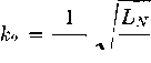 2Й/ \ С в This amphtude is superposed on the backswing as an axis, which, if oscillatory, has frequency/3 determined by LeCn- Since one purpose of good pulser design is the ehmination of false echoes, the backswing axis considered here is always non-oscillatory. Assuming the thyratron is non-conducting for most of the backswing interval, the condition for non-oscillatory backswing is 2Ri for the close part of the backswing 2Re for the distant part where Le is the OCL at time h and J is the ratio of low-frequency core permeability to pulse permeability. If 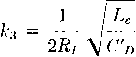 then because generally 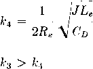 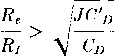 So, if the pulser is designed to prevent distant echoes, /С4 1 and ks is several times the value of fc. Time intervals influenced by these rise without oscillations to final value ai U = 1. This ki has little influence on the trailing edge because is usually small compared to Le. Oscillations occurring close to the traihng edge of the pulse are of frequency/2 (determined by LnCd, where Cd = CdCn/{Cd + Cn), и n is the sum of the transformer leakage and PFN inductance), and of amplitude determined by impedance ratios are illustrated in Fig. 254. In general, for a good pulse, the close part of the backswing axis follows a non-oscillatory pattern of relatively high-impedance ratio, such as those shown on Fig. 235 for /сз > 1. The general effect of pulse transformer magmtizing current is to depress the backswing axis. Magnetizing current does not affect the criterion for absence of false echoes > 1; hence a high ratio J is helpful in eliminating close echoes. The ratio Д of magnetizing current to load current is much less for the close echo than for the distant echo because Rj is less than Re. Close echo Д is ap])roximated by (142) To prevent close echo, the first positive peak of oscillation should be no greater than the negative backswing axis voltage at instant t. Backswing axis voltage may be equated to the am[)litude of the first positive oscillation peak at time 2 in Fig. 254. This equation leads to a transcendental relation between /c2, fc.s, and Д, which is plotted in .002 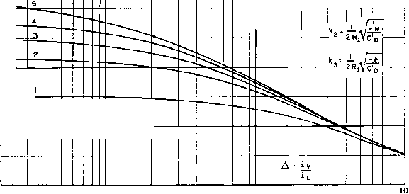 IF PULSER кг EXCEEDS VALUE FROM CURVE , THERE IS NO FALSE ECHO. .01 0.1 Fig. 255. Borderline of close false echoes Fig. 255. It will be noted that all values of /с2 in Fig. 255 are less than unity. Hence, under the conditions here assumed, there is always 1 This equation is developed in the authors False Echoes in Line-Type Radar Pulsers, Proc. I.R.E., 4B, 1288 (August, 1954). a certain amount of high-frequency oscillation superposed on the back-swing axis. But, if is greater than the value given by Fig. 255, there is no false close echo. Because of the approximation represented by equivalent resistance Ri, to prevent false echoes it is best if 2 exceeds the curxe value substantially. For convenience, the various impedance ratios are tabulated in Table XVII. Part of Pulse Affected Front edge Table XVII. Pulser Impedance Ratios Value of Load Resistance Impedance Ratio Defined 2Vl,/C\ Condition for (iood Pulse Shape Ai = 0.5 for min. U with flat-top current pulse Close echo Ri = \/RuRe \ \Ln h value in Fig. 255 for no close echo Backswing axis i I Le close to pulse = VRmR. = -- ks > ki by definition Distant echo ki = 2Re \ Cd к A 1 for no distant echo Example. Suppose that the transformer of Section 134 were used in a linotype modulator with Ljv = 50Aih, Сл = 0.02/if, = V50 X 400 = 141 olims. / = 2.0. Using equation 142, for close echo, Impedance ratios: 2 X 141 550 = 0.52 0.02 X 1,800 X 10-18 (0.02 + 0.0018) X 10- и у - 50 + 2 = 52 Ath 52 X 10 2x 141 \ 1,650 X 10 = 0.628 550 X 10 2X 141 \ 1,650 X 10 - 12 = 2.04 1 2 X 550 X 10 2 X 400 \ 1,800 X 10-12 = 0.98 From ratio we see that the long-term backswing is barely oscillatory. Hence some distant false echo is possible. In Fig. 255, minimum k2 for close false echoes is 0.17. Since k2 calculated above is 0.628, there are no close false echoes with this modulator. According to Fig. 235, the transfoinier has 56 per cent backswing. It can be improved by using 0.002 in. grain-oriented sihcon steel having ju = 1,000 at 5,600 gauss. Le then becomes 1,000 juli, Д = 0.283, = 2.75, and ki = 1.39. Now there are no false echoes, distant or close, and the backswing is 30 per cent. 139. Charging Reactors. In the modulator of Fig. 252, a reactor is used to charge the pulse-forming network to nearly double d-c voltage E. The inductance of this reactor is not critical but should not be so great as to resonate with PFN at a frequency /,- less than half the pulse repetition frequency (PRE). That is, the voltage across PFN would not reach 2E if the resonant-charging frequency лусге less than PRF/2, and the hold-off diode would be useless. It is the function of this diode to prevent discharge of PFN through the d-c source. This makes it possible to use reactors with normal manufacturing tolerances, or with variations in PRE, within the limit set by fr > PRF/2. When no hold-off diode is used, both reactor inductance and PRE must be held to close tolerances, to maintain high Aoltage across PFN, with resonant frequency exactly equal to PRF/2. Linearity of inductance with change in direct current is also necessary for accurate control. Reactors designed by Fig. 71, p. 100, ai-e usually linear enough for the purpose. If fr < PRF/2 the hydrogen thyratron fires before voltage across PFN reaches its peak, but after steady-state conditions obtain this voltage nearly equals 2E. If is low enough, the increase of voltage is approximately linear луНЬ time. This result is called linear charging. Reactor inductance is large in this case, and charging current flows continuously. Here also a range of PRF may be used, all greater than 2fr. Reactor voltages and currents for the three methods of charging are illustrated by Fig. 256. In all cases, Q should be high (more than 10) for efficient pulser operation. Voltages in Fig. 250 are for infinite Q. Voltage is shown for the reactor terminal that connects to PFN. With a hold-off diode, this voltage appears on both terminals during the intervals when current is zero. Without the diode, or if diode and reactor in Fig. 252 are interchanged, the voltage at the left-hand terminal. Fig. 252, is E. Insulation may then be graded accordingly. In all cases, peak voltage across the reactor is E. A-c flux density may be calculated as in a filter reactor, but the effective frequency is 2fr because the flux excursion is in one direction only at frequency Jr. In a-c resonant charging, reactor voltage would increase to QE, where E is the a-c input voltage, if charging continued for a sufficient number of cycles. If reactor Q > 10 and the thyratron is fired at the end of one full charging cycle, maximum PFN voltage is тгЕ'р^, where Epjc is the peak value of applied a-c voltage. In a-c charging the sup- reactor and pfn voltage thyratron fires reactor current reactor linearity 0-c resonant charging with hold-off diode 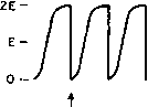  prf< 2fr not important without hold-off diode 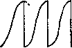 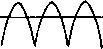 prf: 2fr should be linear for accurate control d-c linear charging 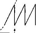 prf> 2ff produces charging linearity Fig. 256. Pulser charging reactor voltage and current. ply transformer inductance may be used instead of a separate reactor and results in somewhat less total weight. A high reactance transformer is useful for this purpose, with shunts as in Section 104. If a hold-off diode is used with a-c charging, an ordinary plate transformer may be used and weight reduced still further. 140. Sweep Generators. Successive pulses, which are separated in time and cause vertical deflection, can be displayed on an oscilloscope by a horizontal sweep. This is the term applied to deflecting means which move the oscilloscope beam horizontally from left to right, usually at a uniform time rate. If the sweep rate is non-uniform, picture distortion results. In magnetic deflection uniform sweep is produced by a sawtooth current which varies linearly with time during the sweep interval. A transformer for magnetic deflection is used in the 1 For a detailed description of a-c charging, see Glasoe and Lebacqz, op. cit., p. 380. circuit of Fig. 257. Pulses of sweep duration r ai)plied to the grid of a beam tetrode cause plate current to increase throughout the pulse. If the transformer had no losses, a pulse of constant amplitude Ea 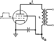 Fig. 257. Tetrode sweep generator. would cause current to increase linearly with time until the pulse ended, in accordance with equation 40; Ea = -L (40a) Losses in a practical transformer are equivalent to a resistance in series with L, and the rise in current is exponential. If the losses are small, current rise may be confined to the part of the exponential curve which is nearly linear, as indicated at the right in Fig. 257. The transformer load is usually the deflection coil of a picture tube. If this coil also has sufficiently low loss, the deflection coil current has the same wave form as the transformer primary, and a linear sweep results. At the end of the pulse, current i does not stop flowing immediately, because of the transformer and deflection coil inductance. A large voltage backswing amplitude results, corresponding to large values of Д in Fig. 235. Values of L, C, and Re are such that the backswing is oscillatory with a period 2т,. which is small compared to sweep duration ts. During T,-, the first or negative half of the backswing oscillation, the oscilloscope beam is usually blanked or cut off quickly, to allow the beam to retrace to the extreme left, ready for the next sweep period. For a bright picture, the retrace i)eriod should be short compared to т^, so that scanning occurs during a large percentage of the time. In television receivers, the sweep frequency is 15,750 cycles and the backswing frequency approximately 77,000 cycles. Thus the retrace time is about 10 per cent of the sweep period. Positive voltage backswing is used in starting the next sweep trace, as will be described later. Magnetic deflection sweep transformers are made with low-loss cores. Manganese-zinc ferrites find wide use here. Design of sweep transformers is closely integrated with the sweep circuit, as will be shown in the next section. Electrostatic deflection is accomplished by application of sawtooth voltages to the horizontal plates of an oscilloscope. Such a voltage is shown in Fig. 258. Sawtooth voltages may be formed in several ways 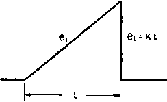 Fig. 258. Sawtooth wave. Fig. 259, Sawtooth transformer circuit. from repetitive pulses. If the pulse requires amplification before being applied to the tube plates, a sweep amplifier is necessary. Here again linearity is important. The spot is moved at a uniform rate across the screen and quickly returned to rei)cat the trace. In such a circuit, the load on the transformer can be regarded as negligible. Assume a linearly increasing voltage as shown in Fig. 258 to be applied to the equivalent circuit of Fig. 259. ei = Kt Then Lpei - LK where p = d{ )/dt, and the voltage across the transformer primary is Lpei Slope of e is Lp + Ri LK (1 - e-) de/dt = ie-/- (143) (144) 1 See Response of Circuits to Steady-State Pulses, by D. L. WaideUch, Proc I.R.E., 37, 1396 (December, 1949). 1 ... 31 32 33 34 35 36 37 38 |
|
© 2026 AutoElektrix.ru
Частичное копирование материалов разрешено при условии активной ссылки |