 |
 |
 |
| Главная Журналы Популярное Audi - почему их так назвали? Как появилась марка Bmw? Откуда появился Lexus? Достижения и устремления Mercedes-Benz Первые модели Chevrolet Электромобиль Nissan Leaf |
Главная » Журналы » Transformer elementary form 1 ... 4 5 6 7 8 9 10 ... 38 TABLE VII - TABLE OF RECTIFIER CIRCUITS TYPE SINGLE PHASe SIMPLE PHASE SINGLE PHASE HALF WAVE FULL WAVE BRIDGE CIRCUIT 3 PHASE HALF WAVE 3 PHASE HALF WAVE ZI6 ZAG DOUBLES PHASE -WITH BALANCE COIL 3 PHASE FULL WAVE {SEC. MAY BE 4) 3 PHASE FULL WAVE ZIS ZAG SIX PHASE HALF WAVE CIRCUITS   PRI. I 141  BALANCE } COIL - +1    RECTIFIER PHASES AND hV¥BE4 OF TUBE? PHASES OF A-C SUPPLY SECONDARY VOLT PER LES 1. 11 (HALF SECT.) I.II (WHOLE) o.ess о.эвэ (HALF LES.4931 o.ess 0.423 0.493 HALF LEG .247 0,74 PRIMARY VOLTAGE 2.22 o.ess o.ess o.ess 0.42e 0.42в 0,74 SECONDARY CURRENT PER LEG L97 oFlJ-U 0.707 jJ-l Jb о.атт 0.S77 OJ\jrL о-гч/т. 0.816 PRIMARY CURRENT PER LEG 1.21 1.000 1.00 0.471 o-Tj-Ot 0.40в 0.408 0.816 0X4/1. 0.816 0-ЛтЛ- 0,S7T SECONDARY KVA 3.48 I.S7 1.11 1.48 1.71 1.48 1.05 1.21 1.81 PRMARY KVA £.66 I.II 1.21 1.09 1.09 I.OS 1.26 AVERAGE OF PRIMARY AND SECOHDARY К V A 1.34 1.35 1.26 I.OS I.IS I.SS INVERSE PEAK VOLTAGE 3. 14 3.14 I.ST 2.09 2.09 2.09 I .OS 1.05 2.09 RMS CURRENT PER TUBE 1.57 0.707 0.707 0.S77 0.577 0.289 0.577 0.577 0.408 PEAK CURRENT PER TUBE 3.14 1.00 1.00 1.00 1.00 0.500 t.oo 1.00 I .00 AVERAGE CURRENT PER TUBE 1.00 0.50 0.50 0,33 0.33 0. I6T 0,33 0.33 0.167 RIPPLE FREOUENCY RMS RIPPLE VOLTAGE 0.472 0.472 0.177 0.177 0.04 0.04 0.04 + 0.057 -0.077 0.042 + 0.067 -0.077 RIPPLE PEAKS + 2.1 4 - LO9 + 0.S7 - 1.00. + 0.57 - 1.00 + 0.209 -0-281 + 0.209 -0-91 Ю.057 -0.077 h0.0S7 -0.077 LINE POWER FACTOR 0.373 0,90 0.90 0,826 0,955 0.9S5 0,955 0,955 0.959 NOTE: THE VALUES OF VOLTAGE AND CURRENT ARE EFFECTIVE OB R,M,SUNLESS OTHERWISE STATEOjTHEY ARE GIVEN IN TERMS OF THE AVERAGE DC.VALUES. AND THE KILOVOLT-AMPERES IN TERMS OF OCKILOKATT OUTPUT PERFECT TRANSFORMERS.RECTlFlERS AND ОС CHOKE ARE ASSUMED. AND N,/Nj I, EXCEPT IN ZIG-ZAG CIRCUITS, SECONDARY AND PRIMARY REFER TO ANODE TRANSFORMER. t FREQUENCY Of BALANCE COIL VOLTAGE 3(. BALANCE COIL VOLTAGE 0.356 PEAK BALANCE COIL VOLTAGE 0.605. BALANCE COIL К VA 0.173. USE COLUMN 5 VALUES FOR HALF VOLTAGE TAR MAGNETIZING CURRENT ASSUMED NEGLIGIBLE IN ALL CASES. This table is based mostly on Polyphase Rectification Special Connections, by R. W. Armstrong, Proc. LR.E., Vol. 19, Jan. 1931- rectified voltage rectified voltage   JIAJV input current (a) ib) Fig. 49. Voltage and current comparisons in reactor-input and capacitor-input circuits. Comparison between the rectified voltage of reactor-input and capacitor-input filters in a single-phase full-wave rectifier may be seen in Figs. 49(a) and (b), respectively. The two tube currents h and I2 in (a) add to a constant d-c output, whereas in (b) the high-peaked tube currents flow only while the rectified voltage is higher than the ripple current which is neglected in the table, and which is considered further in Chapter 4. The single-phase half-wave rectifier ordinarily has discontinuous output current, and its output voltage is therefore highly dependent upon the inductance of the input filter choke. For this reason, the currents and voltages are given for this rectifier \vithout a filter. The difference between primary and secondary v-a ratings in several of these rectifiers does not mean that instantaneous v-a values are different; it means that because of differences in current wave form the rms values of current may be different for primary and secondary. Unbalanced direct current in the half-wave rectifiers requires larger transformers than in the full-wave rectifiers. This is partly overcome in three-phase transformers by the use of zigzag connections. The three-phase full-wave rectifier can be delta-connected on both primary and secondary if desired; the secondary current is multiplied by 0.577 and the secondary \ltage by 1.732. Anode windings have more turns of smaller wire in the delta connection. Single-phase bridge and three-phase full-wave rectifiers require notably low a-c voltage for a given d-c output, low inverse peak voltage on the tubes, and small transformers. 25. Rectifiers with Capacitor-Input Filters. When the filter has no reactor intervening between rectifier and first capacitor, rectifier current is not continuous throughout each cycle and the rectified wave form changes. During the voltage peaks of each cycle, the capacitor charges and draws current from the rectifier. During the rest of the time, no current is drawn from the rectifier, and the capacitor discharges into the load. average d-c voltage. Average current per tube in both cases is half the rectifier output. With large values of capacitance, the rectified voltage о о о о о г- со 01 о g  in Fig. 49(b) increases to within a few per cent of the peak voltage. Ripple, average rectified voltage output, and rectifier current are dependent on the capacitance, the supply line frequency, and the load resistance. They are dependent also on rectifier internal resistance because it affects the peak value of current which the filter capacitor can draw during the charging interval Д^.  voltage and current values have been obtained from experimental measurements by Schadeand are shown in Figs. 50, 51, and 52 for 1 See Diode Rectifying Circuits with Capacitance Filters, by D. L. Waidelich, Trans. AIEE, 61, 1161 (December, 1941). 2 Analysis of Rectifier Operation, by O. H. Schade, Proc. I.R.E., 31, 341 (July, 1943). Analysis of this charge-discharge action involves complicated Fourier series which require a long time to calculate. Satisfactory single-phase half-wave and full-wave rectifiers. In these figures Rs is the rectifier series resistance, including the transformer resistance.  OiVld 3N0> iN3danD aivid swa Results accurate to within 5 per cent are obtained if the rectifier resistance corresponding to peak current Ip is used in finding Rg. The process is cut-and-try, because Ip depends on Rs, and vice л^егва, but two trials usually suffice. Resistance is in ohms capacitance is in farads, and w is 2тг times the supply frequency. Three-phase rectifiers are rarely capacitor-input because of their larger power. In Fig. 52 the peak current indicates whether the peak current of a given tube is exceeded, and the rms current determines the transformer secondary heating. The л^-а ratings are greater, but ratios of primary to secondary v-a ratings given in Table VII hold for capacitor-input transformers also. 26. Voltage Doublers. To obtain more d-c output voltage from a rectifier tube, the circuit of Fig. 53 is often used. With proper values of circuit elements the output is nearly double the a-c peak voltage. Tube inverse peak voltage is little more than the d-c output voltage, and no d-c unbalance exists in the anode transformer. Current output available from this circuit is less than from the single-phase full-wave circuit for a given rectifier tube. Current relations are given in Fig. 52. Voltage tripling and quadrupling circuits also are used, either to increase the d-c voltage or to sivoid the use of a transformer. 27. Filament Transformers. Low-voltage filament transformers are used for heating tube filaments at or near ground potential. Often the filament windings of several tubes are combined into one transformer. Sometimes this requires several secondary windings. In terms of a single secondary transformer a 5 or 6 secondary unit requires about 50 per cent greater size and weight. But these multiwinding transformers are smaller than five or six separate units; this warrants designing them specially in many instances. Rectifier tube filaments often operate at high d-c voltages and require windings with high voltage insulation. It is usually not feasible to combine high-voltage windings with low-voltage windings when the high \ltage is more than 3,000 volts direct current because of insulation difficulties, particularly in the leads. Large rectifier filaments are usually heated by separate transformers; in polyphase rectifiers, all tube filaments are at high voltage, and some secondary windings may be combined. See the three-phase full-wave rectifier in Table VII, where the -\-HV lead connects to a winding which heats the filaments of three tubes. Low capacitance filament windings are sometimes required for high-frequency circuits. The problem is not particularly difficult in small v-a ratings and at moderate voltages. Here air occupies most of the space between windings. In larger ratings the problem is more difficult, because the capacitance increases directly as the coil mean turn 1 See Analyses of Voltage Tripling and Quadrupling Circuits, by D, L. Waidelich and H. A. Taskin, Proc. LR.E., 33, 449 (July, 1945). length for a given spacing between windings. As voltage to ground increases, there comes a point beyond which creepage effects necessitate 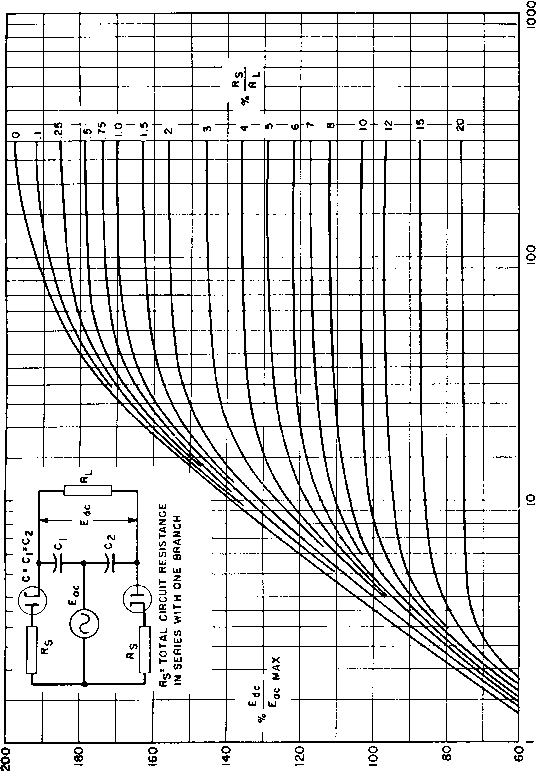 oil-insulated windings, whereupon the capacitance jumps 2 to 1 for a given size and spacing. There is a value of capacitance below which it is impossible to go because of space limitations in the transformer. What this value is in any given case may be estimated from the fact that the capacitance in ix{xi of a body in free space is roughly equal to one-half its largest dimension in centimeters. Except for the differences just mentioned, the design of filament transformers does not differ much from that of small 60-cycle power  riw Ш  Fig. 54. 15 kv filament transformer enclosed in insulating case. transformers. The load is constant and of unity power factor. Leakage reactance plays practically no part, because of its quadrature relationship to the load. Output voltage may therefore be figured as in Fig. 3(c) (p. 8). It should be accurately calculated, however, to maintain the proper filament emission and life. When a tube filament is cold, the filament resistance is a small fraction of its operating value. In large tubes it is often necessary to protect the tube filaments against the high initial current they would draw at rated filament \oltage. This is done by automatically reducing the starting voltage through the use of a current-limiting trans- former having magnetic shunts between primary and secondary windings. The design of these transformers is somewhat special, and is included in Chapter 8. High-voltage filament transformers are sometimes mounted in an insulating case, as in Fig. 54, with the tube socket on top. This arrangement eliminates the need for high-voltage wiring between the transformer and the tube, and provides the insulation for the socket. The problem of air pockets at the base of high-voltage bushings is also eliminated. It is still necessary to insulate well between windings and to fill the case fully with insulating compound in order to eliminate corona. 28. Filament Transformer Design. It is important that design work be done systematically to save the designers time and to afford a ready means of finding calculations at a later date. To attain these ends a calculation form, such as that in Fig. 55, is used. The form is usually made to cover several kinds of transformers, and only the spaces applicable to a filament transformer are used. Suppose that a transformer is required to supply filament power for four single-phase full-wave rectifiers having output voltages of 2,000, 500, 250, and 250 volts, respectively, with choke-input filters, as follows: Primary voltage 100 Frequency 60 cycles Four secondaries for the following tube filaments: 2-872 tubes: 5 volts 13.5 amp Insulated for 4-2000 v d-c 2-866 tubes: 2.5 volts 10 amp Insulated for + 500 v d-c 1-5U4G tube: 5 volts 3 amp Insulated for + 250 v d-c 1-5Y3GT tube: 5 volts 2 amp Insulated for -b 250 v d-c Ambient temperature: 40°C First comes the choice of a core. Data such as those in Fig. 43 are helpful in this, and so is design experience in the modification of such data by the specified requirements. The core used here is a 2-in. stack of laminations A, Fig. 44, which is described more fully in Fig. 56, and has enough heat dissipation surface for this rating. For silicon steel, an induction of 70,000 lines per square inch is practical. The primary turns can be figured from equation 4 by making the substitution Ф = BAc and transposing to E X 10 Ni =- (32) 4:A4:fA,B where Ac is the core cross-sectional area, or product of the core tongue width and stack dimension, and В is the core induction. In this transformer, with 90 per cent stacking factor, = 2 X 0.9 X 1.375 = 2.48 sq in., and the primary turns are found to be 216. 2 * of PUDohlngg 131-caiii Hp К.Т^ДО! - /<Jg /0 it. ft fA oB ..i/i f i,o*zgr 70, ООО Primary /00 Tolta Co Cy. Ina. т.. /. A 4Z7A.CT.2i2aZ T. 32 Z.S 7 /о A 2S VA.CT. -ВЛ Y. 33 T 2 A Z£ VA.CT. 2S0 7. 34 £ v .2 A /g VA.CT. .3g2> y. S5 V A VA.CT T. 36-T-A VA.CT. V. 37 7 A 7A.CT. V. за-2 1 TA.CT. L Plux Density. r Те = - Uwse/ln. Z/ I X :£ > 2 t. /2.sf.en.* /PC I I 2.3- i. t. efi. -X-x £- :-/?.t. W/Sa * -X-- -12-t. iHQjui * X X г t. -r-I- S-t. - -X-X- в-t. - r I = %. Total-. .ТЛ. + e-t.Loeeea. -= fSss prlt та. г prl. T / prl. A
2 Total D 47.? Spaoe + form TC .ISO TP .aw Wdff-Pohg.grad. Wdg{tota) .7.5-/ lllndow Ht. .nS Pohff.terap.Rlee J2 Coll teibp.Rlse Pri. Ind. Volte = VI Total Св. 1дяа /0.01 *л 75 OR /Z Cleararioe J2 See. Ind. Volte X Ng. . °C. Fe lobs °C. Total loeeee = Vp - IH = /00-3 - ?7 2LZ
-32. 2,1 -г - 2nd Trial* ft, - ?.i,/-,/4-X¥7 % /Z S.7.2.-.Z<J,ti.9i lth 2ал /zi. T. Hew Т^/Ир Fig. 55. Filament transformer design calculations. Below this calculation are set down the primary voltage and frequency, and the voltage, current, volt-amperes, and insulation voltage for all secondary windings. These are designated *Si to *S4 for identification. From the sura of the individual v-a figures, the transformer 1 ... 4 5 6 7 8 9 10 ... 38 |
|
© 2026 AutoElektrix.ru
Частичное копирование материалов разрешено при условии активной ссылки |