 |
 |
 |
| Главная Журналы Популярное Audi - почему их так назвали? Как появилась марка Bmw? Откуда появился Lexus? Достижения и устремления Mercedes-Benz Первые модели Chevrolet Электромобиль Nissan Leaf |
Главная » Журналы » Transformer elementary form 1 ... 5 6 7 8 9 10 11 ... 38 rating is found. To it is added an estimate of losses to obtain the input volt-amperes, and the primary current. Next an estimate of the regulation is made (10 per cent) and added to unity to obtain the multiplier 1.1 in the estimate of secondary turns near the top of the calculation form. From the currents listed, the wire size for each winding is chosen. Round enameled wire is used for CORE STACK PRIMARY WINDING CORE TONGUE 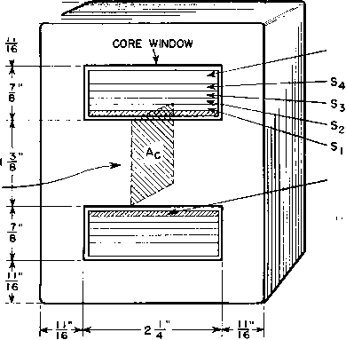 COIL FORM \ X2I,D. THICK WALL 2- LONG MICARTA TUBE Fig. 56. Dimensions and coil section of filament transformer. each winding except *Si, and for it No. 12 square wire is used to save space. The largest wire is placed next to the coil form to prevent damage in winding to the smaller wires. The next task is to find out whether the wdre chosen will fit in the core windoлv space. Winding height D is entered for each winding. For each secondary this is the wire diameter, because the wire is wound in a single layer. D for 5i is slightly larger than the wire dimension to allow for the bulge that occurs wlien square wire is wound. The twelve turns of &x occupy about 1 in. of horizontal winding space. The core window is 2/4 iri- wide. From this is subtracted % in. for clearance, leaving 2% in. total coil width. Margins on each side of *Si are therefore 4(2% - 1/4) = e in. According to Fig. 40 (p. 48) this provides over 8 kv breakdown strength, which is well above the 5-kv test voltage for Si. Other secondary windings have lower test voltages and wider margins, and hence have more than adequate cree age distances. The %6-in.-thick Micarta rectangular tube used for the coil form has a corona voltage of 2,700 rms, which affords about 23 per cent safety factor over the normal operating voltage at the tube filaments. Over Si are wound six wraps of O.OlO-in.-thick treated cloth, which has 2,600-volt corona limit. Winding 2 supplies a filament at 500 volts of the same polarity as <Si. Hence only 1,500 \olts direct current or 1,660 volts alternating current occur across this insulation. At the right of the small sketch in Fig. 55 are listed the number of wraps of 0.010-in.-thick treated cloth over each section of winding. These are added together to give the columnar figure of 0.150 for TC. The primary winding is wound without layer insulation and with an area space factor of 70 per cent. Cotton is wound in with the wire to form walls %e in. thick on either side of the primary; this accounts for the low space factor and for the 1%-in. winding traverse. The coil is finished with two layers of treated cloth, a layer of 0.010-in. fishpapcr for mechanical protection, and a 0.025-in. serving of untreated cotton yarn or tape to hold it together. The total winding adds up to 0.751 in., leaving 0.124 in. clearance, about the right allowance for winding slack for four secondaries. Mean turns are figured from equations 26 and 27, with 5 per cent incremental increase in 82, S3, and aS for leads. With the mean turn values the winding resistances, weights of copper, and IR and PR for each winding can be found. To Si, S2, and S winding resistance is added lead resistance, and the lower figure is the sum of the two in each case. Total copper loss is multiplied by 1.3 to correct for 75°C operating temperature. The core weight is 6.8 lb, and the grade of steel used has 1.17 watts per pound at 70,000 lines per square inch. This gives a core loss of 8 watts, and a total of copper and core loss of 20 watts. After these losses are divided by the appropriate ordinates from Figs, 44 and 45 (pp. 55 and 56) the coil temperature rise is figured at 48 centigrade degrees, which is safe for class A insulation. We know by now that the design is safe, but secondary voltages still must be checked. The method of equation 13 is used. Output voltages on first trial range from 0 to 4 per cent high. S2 voltage is correct but out of line with the rest. Changing So leads to a larger size makes the per cent voltage drops more nearly alike, and increasing the primary turns to 223 brings all output voltages to correct value within 1.2 per cent. Filament voltage should be kept within 2 per cent for these tubes, to allow for meter error. Primary л^oltage per layer is checked at the lower left; this is equivalent to 22.7 volts per mil of wire enamel, which is safe practice. If the design were deficient in any respect, even down to the last things figured, some change would have to be made which would require recalculation of all or part of the transformer; hence the importance of good estimating all the way along. The filament transformer outlined above had a center tap (C.T.) in each filament winding. Such taps are used with directly heated cathodes, especially when plate current is large, to prevent uneven distribution of filament emission. In windings for supplying filaments of small tubes, center taps are sometimes omitted. Ripple in the rectified output then increases, and transformer core flux density becomes asymmetrical. Whether these effects are permissible depends on operating conditions. Usually plate current is much smaller than filament current, so that center-tap leads may be smaller in copper section than start and finish leads. A certain amount of space is required for these leads; rectifier wiring is also more time-consuming when there are center taps. Nevertheless, the extra work and size may be justified by improved performance. An even number of turns, such as were used in the transformer windings described in this section, results in center-tap placement on the same coil end as the start and finish leads; if there were an odd number of turns, the tap lead would be at the opposite end. In a single-core, single-coil design, an odd number of turns cannot be center-tapped exactly. Usually the unbalance caused by the tap being a half-turn off center is not serious, but it should not be disregarded лvithout calculation. 29. Anode Transformers. Anode transformers differ from filament transformers in several respects. (a) Currents are non-sinusoidal. In a single-phase full-wave rectifier, for instance, current flows through one half of the secondary during each positive voltage excursion and through the other half during each negative excursion. For half of the time each half-secondary winding is idle. (b) Leakage inductance not only determines output voltage but also affects rectifier regulation in an entirely different manner than with a straight a-c load. This is discussed in Chapter 4. (c) Half-wave rectifiers carry unbalanced direct current; this may necessitate less a-c flux density, hence larger transformers, than full-wave rectifiers. Unbalance in the three-phase half-wave type can be avoided by the use of zigzag connections, but an increase in size over full-wave results because of the out-of-phase voltages. These connec- tions are desirable in full-wave rectifiers when half voltage is obtained from a center tap. See Table VII. {d) Single-phase full-wave rectifiers with two anodes have higher secondary volt-amperes for a given primary v-a rating than a filament transformer. Bridge-type (four-anode) rectifiers have equal primary and secondary volt-amperes, as well as balanced direct current, and plate transformers for these rectifiers are smaller than for other types. Three-phase rectifier transformers are smaller in total size but require more coils. The three-phase full-wave type has equal primary and secondary v-a ratings. (e) Induced secondary voltage is much higher. Filament transformers are insulated for this voltage but have a few secondary turns CORE 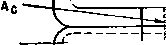 (KXXXX><SEC.v>W 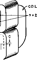 Fig, 57. Dimensions and coil section of anode transformer. Construction shown is for shell-type transformer with 2 Hipersil cores. of large wire, whereas anode transformers have many turns of small wire. For this reason the volts per layer are higher in anode transformers, and core windows having proportionately greater height and less width than those in Fig. 56 are often preferable. This trend runs counter to the conditions for low leakage inductance and makes it necessary to interleave the windings. Figure 57 shows the windings of a single-phase full-wave rectifier transformer with the primary interleaved between halves of the secondary. This arrangement is especially adaptable to transformers with grounded center tap. The primary-secondary insulation can be reduced to the amount suitable for primary to ground. This is called graded insulation. In large power rectifiers of the gas-filled or pool types, anode current under short-circuit conditions may be very great, and anode transformer windings must be braced to prevent damage. If the conductors are small, solventless varnish is useful for solidly embedding the conductors. 30. Leakage Inductance. Flux set up by the primary winding which does not link the secondary, or vice versa, gives rise to leakage or self-inductance in each winding without contributing to the mutual flux. The greater this leakage flux, the greater the leakage inductance, because the inductance of a winding equals the flux linkages with unit current in the winding. In Fig. 57, all flux which follows the core path Ic is mutual flux. Leakage flux is the relatively small flux which threads the secondary winding sections, enters the core, and returns to the other side of the secondaries, without linking the primary. The same is true of flux linking only the primary winding. But it is almost impossible for flux to leave the primary winding, enter the core, and re-enter the primary without linking part of the secondary also. The more the primary and secondary windings are interleaved, the less leakage flux there is, up to the limit imposed by flux in the spaces с between sections. These spaces contain leakage flux also; indeed, if there is much interleaving or if the spaces с are large, most of the leakage flux flows in them. Large coil mean turn length, short winding traverse b, and tall window height a all increase leakage flux. Several formulas have been derived for the calculation of leakage inductance. That originated by Fortescue is generally accurate, and errs, if at all, on the conservative side: 10ШЧ1Т(2пс + a) =-M- where Ls = leakage inductance of both windings in henrys, referred to the winding having N turns MT mean length of turn for whole coil in inches n = number of dielectrics between windings (n = 2 in Fig. 57) с == thickness of dielectric between windings in inches a = winding height in inches Ъ = winding traverse in inches. The greatest gain from interleaving comes when the dielectric thickness с is small compared to the window height; when nc is comparable to the window height, the leakage inductance does not decrease much as n is increased. It is often difficult to reduce the leakage inductance which occurs in high-\oltage transformers because of leakage flux in 1 See Standard Handbook for Electrical Engineers, McGraw-Hill Book Co., New York, 1922, 5th ed., p. 413. spaces c. A small number of turns, short mean turn, and low, wide core windows all contribute to a low value of leakage inductance. 31. Anode Transformer Design. Let the requirements of a rectifier 1,200 volts 115 ma rectifier d-c output Single-phase full-wave circuit with 866 tubes Primary 115 volts 60 cycles Rectifier regulation 5 per cent maximum Ambient 55C To fulfill these requirements, a reactor-input filter must be used. If 1 per cent is allowed for reactor IR drop, a maximum of 4 per cent regulation is left in the anode transformer. The approximate secondary output voltage is 1,200 X 2.22 = 2,660, say 2,700 volts. The center tap may be grounded. Suppose that a transformer like the one in Fig. 57 is used. The calculations are given in Fig. 58. The various steps are performed in the same order as in filament transformers. The grain-oriented type С core is worked at 38 per cent higher induction, \vith but 60 per cent of the core loss of Fig. 55; its strip width is 2/4 in., build-up % in., and window 1 in. by 3 in. for each core loop. Note the difference in primary and secondary \olt-amperes and winding heights. Since the primary and secondary are symmetrical about the primary horizontal center line, they have the same mean turn length. Losses and temperature rise are low. Regulation governs size. Secondary layer voltage is high enough to require unusually thick layer paper. This coil is wound on a multiple-coil machine. Winding height is figured on the basis of layer paper adequate for the \ltage instead of from Table VI (p. 39), but turns per layer are taken from this table. Since adjacent layers are wound with opposite directions of traverse, the highest voltage across the layer insulation is twice the volts per layer. Layer insulation is used at 46 volts per mil in the secondary; this counts the 1.7 mils of double enamel, which must withstand impregnation without damage. Anode leads and margins withstand 5 kv rras test voltage. Since the secondary center tap is grounded, two thicknesses of 0.010-in. insulation between windings are sufficient. Clearance of 0.253 in. allows room for in-and-out coil taping. Secondary leakage inductance, from equation 33, is 10.6 X 4,200 X 10.2(4 X 0.020 + 0.747) -- ----= 0.166 henry 4 X 2.375 X 10 At 60 cycles this is 6.28 X 60 X 0.166 = 63 ohms, which would be 240 ohms if the secondary were a single section, and which would increase regulation as set forth in Chapter 4. The regulation calcu- Corel. ins.
.Пшс Penalty 9i..<p Unee/ln. ly t. л^А^пх x-,x. -X-.X -X- sec. Total. A*. zxo ТА. + Eet.Lossee -x--Z . X. .X. . X. . X. -X-. X- -t. .t. -t. -t. -t. t. prl. V JJls. prl. л
T- TT? tfy t lotal D Spaeo -f Form. FP CT 1Йв( total) \ Window Ht. J.ooa Clearanoe . .si Me-Pohe.grad. /3.7 Pohe.temp.RleeZZ2I Coll temp.RlBe S2./ prl. Ind. Volte VI 360. Ind. Volta - Tj Total Ca. Loee. °C. . >t 7 OR C. Fb loee.7>7.tf6. .°C. Total loeeee . = Vp - IR = S-2.n - и.яз X H..
*wlth New T1/Ne Fig. 58. Anode transformer design calculations. lated in Fig. 58 is that due to primary IR calculated in the normal manner, plus Io times one-half the secondary winding resistance. When high voltage is induced in a winding, the layer insulation and coil size may often be reduced by using the scheme showm in Fig. 59. This is applicable to a plate transformer of the single-phase full-wave PRESSBOARD SPACER r(lF USED}
fin. type with center tap grounded. It then becomes practical to make the secondary in two separately wound vertical halves or part coils. One of the part coils is assembled with the turns in the same direction as those of the primary, and the other part coil is reversed so that the turns are in the opposite direction. The two start leads are connected together and to ground as in Fig. 59. It is necessary then to provide only sufficient insulation between windings to withstand the primary test voltage. Channels may be used to insulate the secondaries from the core. With higher voltages, it may be necessary to provide pressboard spacers between the secondary part coils, or to tape the secondary coils separately, birt margins must be provided sufficient to prevent creepage across the edges of the spacers. 32. Combined Anode and Filament Transformers. Anode and filament windings are combined into a single transformer mainly in low-power ratings such as those in receivers and grid bias power supplies. COIL FORM Fid. 59. Anode tran.sformer with CT. grounded. 115V. 50/60 CY.  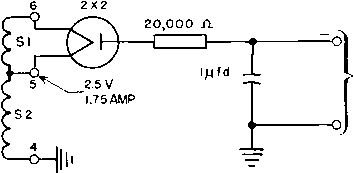 6.3V 0.6 AMP Fig. 60. Power supply transformer. 2 ma. D.C. LOAD 1700 VD.C. One widely used combination includes the anode and filament windings for a rectifier and a filament winding for the amplifier tubes. Figures 60 and 61 show how winding insulation sometimes may be graded to require a minimum of insulation and space. The high-voltage filament winding *Si is placed over the coil form to take advantage of its thick insulation. Layer insulation is sufficient between Si and S2, and between and (S3. Over and under the primary winding is 115-volt COIL FORM Fig. 61. Winding arrangement to save insulation. insulation. Thus Fig. 61 is a high-voltage transformer with no high-voltage insulation in it except what is incidental to the coil form. Combined anode and filament transformers are difficult to test for regulation or output voltage aside from operation in the rectifier circuit itself, because a-c loads do not duplicate rectifier action. Most transformers of this kind are used in rectifiers with capacitor-input filters or with fixed loads in which regulation is not important. Ratings are easier to predict. Anode secondary v-a rating is the product of rms voltage and current, but the corresponding portion of primary v-a rating depends on the rectifier and is found as mentioned in Sections 24 and 25. To this is added the sum of filament winding v-a ratings, and the primary current can then be calculated from the total volt-amperes. 33. Power Supply Frequency. Foregoing examples were based on a 60-cycle supply. Twenty-five-cycle transformer losses are lower for a given induction. It follows that induction can be increased somewhat over the 60-cycle value, but saturation currents prevent a decided increase. Larger size results, nearly 2:1 in volume. Otherwise 25-cycle transformers are not appreciably different from 60-cycle transformers. Power supply frequencies of 400 and 800 cycles are used mainly in aircraft and portable equipment to save weight and space. Silicon-steel core materials 0.005 in. thick arc principally used at these frequencies to reduce eddy currents. Losses at 400 and 800 cycles for three core materials are shown in Fig. 62. These losses can be the controlling factors in determining transformer size, because a given material saturates at nearly the same induction whether the frequency is 60 cycles or 800 cycles, but the core loss is so high at 800 cycles that the core material cannot be used near the saturation density. The higher the induction the higher the core heating. For this reason, class В insulation can be used in many 400- and 800-cycle designs to reduce size still further. If advantage is taken of both the core material and insulation, 800-cycle transformers can be reduced to 10 per cent of the size of 60-cycle transformers of the same rating. Typical 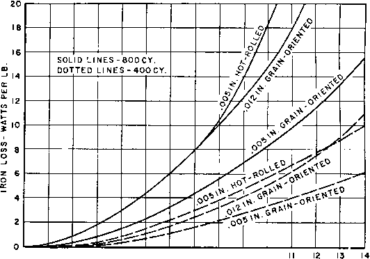 5 6 7 8 9 10 INDUCTION-KILOGAUSS Fig. 62. Silicon-steel core loss at 400 and 800 cycles. combinations of grain-oriented core material and insulation are as follows: Strip Class of Operating Frequency Thickness B-Gauss Insulation Temperature 60 0.014 15,000 A 95 °C 400 0.005 12,500 В 1400 800 0.005 8,500 В 140 °C In very small units, these flux densities may be used at lower temperatures and with class A insulation because of regulation. The special 4-mil steel developed for 400 cycles makes possible size reduction comparable to that for 800 cycles. The necessity for small dimensions, especially in aircraft apparatus, continually increases the tendency to use materials at their fullest capabilities. Many small 60-cycle transformers have core loss which is small compared to winding or copper loss. This condition occurs because inductance is limited by exciting current rather than by core loss. As size or frequency increases, this limitation disappears, and core loss is limited only by design considerations. Under such circumstances, the ratio of core to copper loss for maximum rating in a given size may be found as follows. Let 1 ... 5 6 7 8 9 10 11 ... 38 |
|||||||||||||||||||||||||||||||||||||||||||||||||||||||||||||||||||||||||||||||||||||||||||||||||||||||||||||||||||||||||||||||||||||||||||||||||||||||||||||||||||||||||||||||||||||||||||||||||||||||||||||||||||||||
|
© 2026 AutoElektrix.ru
Частичное копирование материалов разрешено при условии активной ссылки |