 |
 |
 |
| Главная Журналы Популярное Audi - почему их так назвали? Как появилась марка Bmw? Откуда появился Lexus? Достижения и устремления Mercedes-Benz Первые модели Chevrolet Электромобиль Nissan Leaf |
Главная » Журналы » Transformer elementary form 1 ... 6 7 8 9 10 11 12 ... 38 WeW.. EI = = KVWeiK - We) For a maximum, the rating may be differentiated with respect to W and the derivative equated to zero: whence We = so that Ws - K3/2, or copper and core losses are equal for maximum rating. Although this equality is not critical, and is subject to many limitations such as core shape, voltage rating, and method of cooling, it does serve as a guidepost to the designer. If a transformer design is such that a large disparity exists between core and copper losses, size or temperature rise often may be reduced by a redesign in the direction of equal losses. 34. An 800-Cycle Transformer Design. Primary 120 volts 800 cycles Rectifier to deliver 0.2 amp at --450 volts using 5U4G in single-phase full-wave circuit with O.b-fiM capacitor input filter. Figures 51 and 52 tell whether the product mCRl will produce the necessary d-c output without exceeding the rectifier tube peak inverse voltage rating and peak current rating. o>CRl = 6.28 X 800 X 0.5 X 10 X (450/0.2) = 5.65 For Rs assume a peak current of 0.5 amp. Average anode character- We = core loss Ws = copper loss Ki, K2, etc. = constants E = secondary voltage / = secondary current For a transformer with a given core, winding, volt-ampere rating, and frequency, We KiE. For a given winding, И^ = K2P. Also, for a given size, We + Ws = K, a quantity determined by the permissible temperature rise. Hence the transformer volt-ampere rating is approximately istics show 97 volts tube drop, or 97 0.5 = 194 ohms at peak current. Rs/Rl = 194/2,250 = 0.086. Add 5 per cent for transformer windings; estimated Rs/Rl = 13.6 per cent. Check on Peak Current from Fig. 52. noiCRb = 11.3 Ip = Ыр = 5 X 0.1 = 0.5 amp the peak value assumed. Rms current in tube plates and secondary windings is 2 X 0.1 - 0.2 amp. Output voltage, from Fig. 51, is 0.69 peak a-c voltage per side. Hence secondary rms voltage per side is 450 X 0.707 0.69 460 volts, and secondary volt-amperes = 2 X 460 X 0.2 - 184. The anode transformer must deliver 2 X 460 = 920 volts at 0.2 amp rms. Primary volt-amperes = 0.707 X 184 - 130. Inverse peak voltage is the peak value of this voltage plus the d-c output, because the tube filament is at d-c value, plus a small amount of ripple, while one anode has a maximum of peak negative voltage, during the non-conducting interval. Thus peak inverse voltage is 460 X 1.41 + 450 - 1,100 volts, which is within the tube rating. Choice of core for this transformer is governed by size and cost considerations. Assume that the core works at 8,500 gauss. The loss per pound for 0.005-in. silicon steel and grain-oriented steel is 12.2 and 6.6, respectively. (See Fig. 62.) But punchings have 80 per cent stacking factor, whereas the type С core has 90 per cent. In this thickness 0.005-in. grain-oriented steel compares still better with ordinary silicon steel than Fig. 62 would indicate and so will be used for the core. Let two type С cores be used with the following dimensions: Strip width % in. Window height % in. Build % in. Window width 1Ц, in. Total net core area 0.506 sq in. Core weight 0.75 lb Turns could be figured from equation 32, except that the induction is in gauss. Since many core data are given in gauss, equation 32 is changed for convenience to 3.49; X 10** Nr =- (34) where dimensions are in inches and В is in gauss. Primary turns are then 84 ELECTRONIC TRANSFORMERS AND CIRCUITS 3.49 X 120 X 10 = 122 800 X 0.506 X 8,500 Final design figures are: Primary 122 turns No. 26 glass-covered wire d-c resistance 1.8 ohms Secondary 900 turns No. 29 glass-covered wire d-c resistance 38 ohms Primary copper loss at 100°С = 3.35 watts Secondary copper loss at 100°С = 2.04 watts Core loss 6.6 X 0.75 - 4.95 watts Total losses 10.34 watts With an open-type mounting and mica insulation this transformer has a temperature rise of 75 centigrade degrees. 35. Polyphase Transformers. In large power rectifiers three-phase supplies are generally used. Accurate phase voltages must be maintained to avoid supply frequency ripple in the output. Delta-connected primaries are shown in Table VII for the various rectifiers; these are preferable to open-delta because phase balance is better, and to Y-connections because of possibly high third harmonics. Open-delta connections require only two single-phase transformers instead of three, but a similar saving may be had by using a single core-type three-phase unit which retains the phase-balance advantage. The main drawback to a three-phase core is its special dimensions. Often, to use standard parts, three single-phase units are employed in the smaller power ratings. But if the power is hundreds or thousands of kilowatts, the cores are built to order, and the weight saving in a three-phase core is significant. Two- and three-phase filament transformers are used with output tubes for large broadcast stations to heat filaments uniformly and reduce hum in the r-f output. 36. Design Chart. In preceding sections, it has been stated that special conditions require tailored designs. Windings for simple low-voltage 60-cycle transformers may be chosen from the chart of Fig. 63. This chart is based upon the following conditions: (a) Two untapped concentric windings; primary wound first. (b) Operating voltage in both windings less than 1,000 volts. (c) Power supply frequency 60 cycles. (d) Maximum temperature rise 40°C in 65°C ambient. (e) Resistive loads.
(/) Equal PR losses in primary and secondary. (g) Solventless resin impregnated coils. [h) Open-type assemblies like those of Fig. 15. (г) Grain-oriented silicon-steel cores. It was found that 40°C rise in the four smallest sizes resulted in excessive voltage regulation. For example, a small filament transformer would deliver correct filament voltage at room ambient temperature of 25 °C, but at 105°С this voltage dropped to less than the published tube limit. Hence the winding regulation in the two smallest transformers was limited to 15 per cent, and in the next two larger sizes to 10 per cent. In still larger sizes, the 40°C temperature limit held the regulation to less than 10 per cent. In using the chart, ratings rarely fall exactly on the v-a values assigned to each core. Hence a core is generally chosen with somewhat greater than required rating. Lower regulation and temperature rise than maximum then result. Wire size in quadrant I also increases in discrete sizes, and if the chart indication falls between two sizes the smaller size should be used. Instructions for Using Fig. 63. 1. Choose a core from Table VIII which has a v-a rating equal to or greater than that required. 2. From rated primary and secondary voltages, find number of turns for both windings in quadrant IV. 3. From rated primary and secondary currents, find wire size for both windings in quadrant 1. 4. Project turns across to quadrant III to obtain winding resistances. Table VIII. Transformer Size, Rating, and Regulation
30 20 108 6 4 3 г I .8 .6 4 3 AMPERES O.t .06 .04 .03 .02 .01 Ш OHMS 1000 600 400 гоо юо бо 4o зо го ю 6 4 з г i .8 .6 .4 .з г aio8.06.04.03 .ой .oi 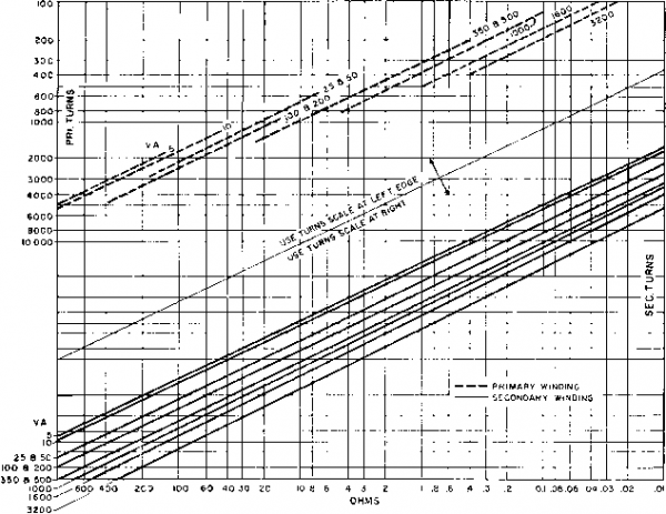 Fig. 63. Low-voltage 60-cycle transformer design chart. 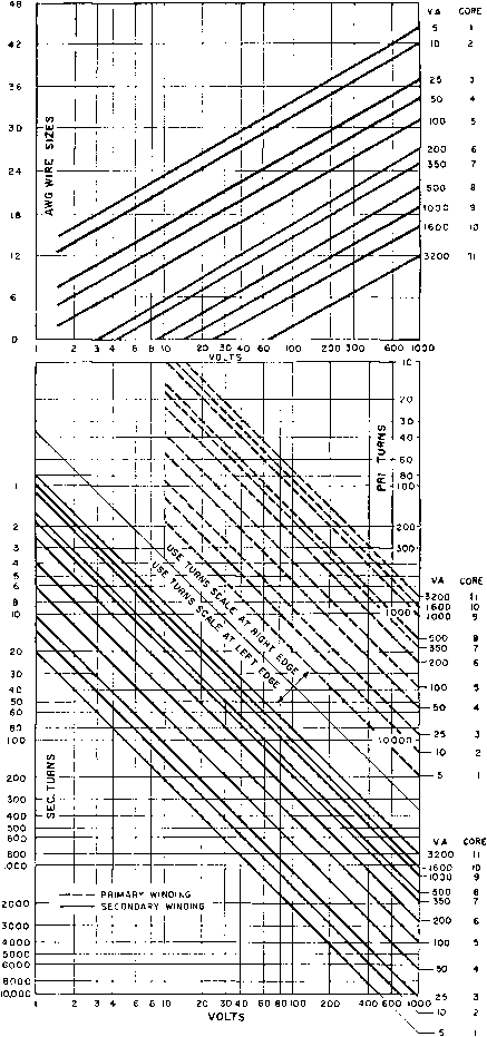 Ж Fig. 63. (Continued) Departures from the assumed conditions preclude direct application of Fig. 63, but the chart is still useful as a starting point in design. For some common modifications, the following notes apply: 1. For each additional secondary winding reduce core maximum rated volt-amperes by 10 per cent. Choose wire size from quadrant II. 2. For 50-cycle transformers, reduce core maximum rated v-a 10 per cent. 3. When permissible temperature rise is higher than 40°C, core maximum volt-amperes equal (v-a in table) X Vemperature rise/40°C. Example. A transformer is required for 115/390 volts, 60 cycles, to deliver 77 volt-amperes. This rating falls between the maxima for cores 4 and 5. Using core 5 at 115 volts, we read, from Fig, 63, for the primary, 440 turns of No. 22 wire and 3 ohms d-c resistance; for the secondary, 1,700 turns of No. 27 wire and 40 ohms d-c resistance. 37. Reactors. Reactors are used in electronic power equipment to smooth out ripple voltage in d-c supplies, so they carry direct current in the coils. It is common practice to build such reactors with air gaps in the core to prevent d-c saturation. The air gap, size of the core, and number of turns depend upon three interrelated factors: inductance desired; direct current in the winding; and a-c \olts across the winding. The number of turns, the direct current, and the air gap determine the d-c flux density, whereas the number of turns, the volts, and the core size determine the a-c flux density. If the sum of these two flux densities exceeds saturation value, noise, low inductance, and non-linearity result. Therefore a reactor must be designed with knowledge of all three of the conditions above. Magnetic flux through the coil has two component lengths of path: the air gap Ig, and the length of the core Ic. The core length Ic is much greater geometrically than the air gap Ig, as indicated in Fig. 57, but the two components do not add directly because their permeabilities are different. In the air gap, the permeability is unity, whereas in the core its value depends on the degree of saturation of the iron. The effective length of the magnetic path is Ig(Ic/fJ-), where p. is the permeability for the steady or d-c component of flux. Reactor design is, to a large extent, the proportioning of values of air gap and magnetic path length divided by permeability. If the air gap is relatively large, the reactor inductance is not much affected by changes in ju,; it is then called a linear reactor. If the air gap is small, changes in fi due to current or voltage variations cause inductance to vary; then the reactor is non-linear. When direct current flows in an iron-core reactor, a fixed magnetizing force Hdc is maintained in the core. This is shown in Fig. 64 as the vertical line Hdc to the right of zero Я in a typical a-c hysteresis loop, the upper half DBD of which corresponds to that in Fig. 21. Increment ДЯ of a-c magnetization, superposed on Hdcj causes flux density increment Д5, with permeability equal to the slope of dotted line ABrn. B is twice the peak a-c induction Вас- It will be recalled from Fig. 19 that the normal induction curve OBm. is the locus of the end points of a series of successively smaller major hysteresis loops. Since the top of the minor loop always follows the left side of a maj or loop, as Hdc is reduced in successive steps the upper ends of corresponding minor loops terminate on the normal induction curve. Dotted-hne slopes of a series of minor loops are shown in Fig. 64, 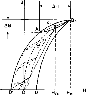 Fig. 64. Incremental permeability with different amounts of d-c magnetization. the midpoints of which are (7, C, C , and C . Increment of induction дБ is the same for each minor loop. It will be seen that the width of the loop AH is smaller, and hence }xa is greater, as Hdc is made smaller. Midpoints C, C, etc., form the locus of d-c induction. The slope of straight line ОС is the d-c permeability for core magnetization Hdc- It is much greater than the slope of AB. Hence incremental permeability is much smaller than d-c permeability. This is true in varying degree for all the minor loops. The smaller AB is, the less the slope of a minor loop becomes, and consequently the smaller the value of incremental permeability /хд. The curve in Fig. 65 marked д is the normal permeability of 4% siHcon steel for steady values of flux, in other words, for the d-c flux in the core. It is 4 to 20 times as great as the incremental permeability /ла for a small alternating flux superposed upon the d-c flux. The ratio of ix to /ид gradually increases as d-c flux density incr ases. Because of the low value of jua for minute alternating voltages, the effective length of magnetic path Ig + (Ic/pa) is considerably greater for alternating than for steady flux. But the inductance varies inversely as the length of a-c flux path. If, therefore, the incremental permeability is small enough to make 1с/}ла large compared to Ig, it follows that small 12,000 10,000 8,000 6,000 4,000 2,000
8 10 12 B-KILOGAUSS Fig. 65. Normal and incremental permeability of 4% silicon steel. variations in Ig do not affect the inductance much. For this reason the exact value of the air gap is not important wdth small alternating voltages. Reactor size, with a given voltage and ratio of inductance to resistance, is proportional to the stored energy LP. For the design of reactors carrying direct current, that is, the selection of the right number of turns, air gap, and so on, a simple method was originated by C. R. Hanna. By this method, magnetic data are reduced to curves such as Fig. 66, plotted between LP/V and NI/lc from which reactors can be esigned directly. The various symbols in the coordinates are: 1 Design of Reactances and Transformers Which Carry Direct Current, by C. R. Hanna, J. AIEE, 46, 128 (February, 1927). a-c inductance in henrys direct current in amperes volume of iron core in cubic inches Ach (see Fig. 57 for core dimensions) Ic = N = I, = cross section inches length of core in inches number of turns in winding air gap in inches (x id *)
о 20 40 60 80 100 120 Fig. 66. Reactor energy per unit volume versus ampere-turns per inch of core. Each curve of Fig. 66 is the envelope of a family of fixed air-gap curves such as those shown in Fig. 67. These curves are plots of data based upon a constant small a-c flux (10 gauss) in the core but a large Ac = cross section of core in square 1 ... 6 7 8 9 10 11 12 ... 38 |
||||||||||||||||||||||||||||||||||||||||||||||||||||||||||||||||||||||||||||||||||||||||||||||||||||||||||||||||||||||||||||||||||||||||||||||||||||||||||||||||||||||||||||||||||||||||||||||||||||||||||||||||||||||||||||||||||||||||||||||||||||||||||||||||||||||||||||||||||||||||||||||||||||||||||||||||||||||||||||||||||||||||||||||||||||||||||||||||||||||||||||||||||||||||||||||||||||||||||||||||||||||||||||||||||||||||||||||||||||||||||||||||||||||||||||||||||||||||||||||||||||||||||||||||||||||||||||||||||||||||||||||||||||||||||||||||||||||||||||
|
© 2026 AutoElektrix.ru
Частичное копирование материалов разрешено при условии активной ссылки |