 |
 |
 |
| Главная Журналы Популярное Audi - почему их так назвали? Как появилась марка Bmw? Откуда появился Lexus? Достижения и устремления Mercedes-Benz Первые модели Chevrolet Электромобиль Nissan Leaf |
Главная » Журналы » Preparation instrucnons requirements 1 ... 7 8 9 10 11 12 13 ... 43 bCL-std-skse: 14 JULY 1989 ICTTOD 508.3 RAIN SECTION II II-l APPARATUS II-l.l Teat-faGilitv A. Fop procedure I. the rain facility shall have the cabiiity Of p54Xii£ing falling rain acccnpanied by wind blowing at ths rats specified herein. The facility tenperattw-e shall be uncontrolled, except as regulated by water introduced as rain. The rain shall be produced by a water distribution device of such design that the water is emitted in the form of droplets having a diameter range predominant 1 ly between 0.5 and 4.5 millimeters (1-3.2c). The rain shall be dispersed coirpletely over the test item №en acconpanied by the prescribed d.nd. b. The wind source shall be positioned n,th respect to the test item so that it will cause the rain to beat directly, with variations ijp to 45° from the horizontal, and uniformly against one side of the test item. The wind source shall be capable of producing horizontal wind velocities equal to and exceeding 18 m/s (40ini/h). The wind velocity shall be measured at the position of the test item before placement of the test item in the facility. Kg rust or corrosive contaminants shall be isposed on the test Item by the test facility. c. A water-soluble dye such as fluorescein may be added to the rainwater to aid in locating and analyzing water leaks. d. For procedure II, the test setijp should provide a volume of water greater than 280 (+30, -0) L/m/h (7 gal/ft./h) dripping from a dispenser with drip holes on a 25.4 mn pattern, as shown in figure 506.3-1. e. For procedure III, the nozzles used should produce a square spray pattern or other overlapping pattern (for maximLim surface coverage) and droplet size predominantly in the 2 to 4.5 mm range at approxinately 375 kPa (40 psig). At least one nozzle should be used for each 6 ft of stjrface area and should be positioned 19 ±1 in. from the test surface. / II-l.2 Controls a. For procedures I and II, the rainfall rate shall be verified imediately before each test. b. For procedure I, the air velocity shall be verified imnediately before each test. 3/ From MIL-s-55286 and MIL-S-55541. kethod 506.3 U JULY 1989 WATER INLET HEIGHT ADJUSTABLE WATER LEVEL 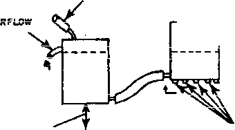 A г 1.5 mm (DIMPLES) WATER DROPLETS L5 DEEP DIMPLES PREYED INTO 0.8mm BRASS PLATE WITH 4.S.T..T. MILDSTEEL ROD WITH A S mm END RADIUS HOLES (0.S3mm OIA) DRILLED THR0U(*H DIMPLES IN aSmm BRASS PLATE 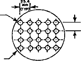 VIEW A-A 25.4mm(TYP) ПЛигщ 50a.3-l. t tall of Р1 рел вг for DpIp Г тЬ Step 1. Stabilize the teat item at standard aabient conditions per (ieneral Bequirements. 5.1a, in the test enaaber. if applicable. Step 2. Conduct a coaplete visual essBsination of U>e test item. HCfTE: Ho sealing, taping, caulking, etc., shall be used except as required in the test item drawings. Step 3. Docunant tbe results. Step 4. Prepare ths test itesa in accordanoe -ith Gsne~l Bequir snts, 5,2.2 and required test item configiB>ation. Step 5. Conduct an operatlcmal checkout in accordance with tbe improved test plan. Step 8. Bsccrd tba results for ccspliance sith (Ssnsral Bsquiroasnts. 5.2.8. Step 7. If the test item operates satisfactorily, proceed to II-3. If not. reaolve the problems and restart at step 1. II-3. FBOCEDDHES. The following test procedures provide the basis for collecting the necessary information concerning the test items waiertisnurieH. Proceed te the first procedure as specified in the test plan. lETKDD 506.3 c. For procedure III. the nozzle spray pattern and preseure shall be verified before each test. d. Qnless otherwise specified, water used for rain tests can be from local water supply sources. II-1.3 Test interruption. (Qeneral Bsquiromsnts. 5.2.4) a. wiqertesi intarrwtion. Intenniption cf a rain test is vsillksly tc generate any adverse effects, and normally the test slll be continued from the point of interruption. II-2 ITEPHATIOW РОР.Яет 11-2.1 Preliminary steps. Before initiating any testing, determine from the test plan: a. Which test procedures are required. b. The rainfall rate and wind velocity for procedure I. s. The other variables pllcable tc the desired procedure. II-2.2 Pretest standard astoient chedtout. All test items require a pretest standard anbient checkout to provide baseline data. Conduct the cbeckout as folic MIL-STD-eiOE U JULY 1080 II-3.1 ProgftfyPf I г PowlTtf r<4n Step 1. with the test item in tbe facility aitd in its nopmal operating ix>eition. adjust the rainfall rate as specified in tbe test plan. ПЪе sealed test item shall be either heated to a higher tenperature than the rain mater (see 1-4.2), or tbe wmter nmy be cooled. Tbe test item shall be restored to its normal operating configuration isaadiately before testing.) Step 2. Initiate the wind at the velocity specified in the test plan and maintain for at least 30 ndnutes. Step 3. If an operational check is required, the test item shall be operated for the last 10 ndnutes of the 30-minute rain. Step 4. Rotate the test item to expose to the rain source any other side of the test item that could be exposed to blovn rain in its deployment cycle. Step 5. Repeat steps 1 through 4 wtil all possible variations have been acconplished. Step e. Examine the test item in the test chanber, if possible; otherwise, remove the test item from the test facility and conduct a visual inspection. If a noticeable amount of free water has penetrated the test item, judgment nust be used before operation of the test item. It may be necessary to enpty water from the test item to prevent a safety hazard. Measure the volume of water. Step 7. Meas\jre and document юу free water found inside the protecUKl areas of tbe test item. Step 8. If required, operate tbe test item for conpliance with tbe requireomnts docunent. Step 0. Docunent the results. II-3.2 Procedure II - Drip Step 1. Install the test item in the facility in accordance with Gteneral Requirements, 5.2.2, in its operational configuration with all connectors and fittings engaged. (Tbe sealfKl test item shall be heated to a higher tenperatxjre than the rain water (see 1-4.2) and restored to its normal operating configuration inaiediately before testing.) Step 2. With the test item operating, subject it to water falling from a height of jproxiaately 1 mster (3 feet) at a uiiform rate (as produced fay a 75-nitt-high mter level in the dispenser) for 15 minutes (see figure 508.3-1). Tbe test set4> shall be arranged so that all of the upper sxsrface gets droplets on it at some time during the test. Test items with glass-covered instrunents shall be tilted at a 45*=* angle, dial up. №ТЮО 506.3 IDL-STD-SIOS 14 JULY lOeP Step 3. At the conclusion of the 15-minute expoeure, renove tbe test item from the test facility and remove sufficient panels or covers to allow the interior to be Smm. Step 4. Visually inspect the test item for evidence of mter penetration. Step 5. Measure and docunent any free water inside tbe test item. Step 6. Gonduet an operational cheek ox the test item as specified In the test plan, and doctnent the restilts. II-3.3 Procedure III - lfcterti<htness Step 1. Install the teat item in the test facility with all doors, lowers, etc.. closed. Step 2. Position the nazzlss ss required by the test plan or as i;x!i ted in Il-l.le. Step 3. Spray al 1 exposed s\s>faces of the test item with water for not less than 40 minutes per face. Step 4. After each 40-Biinuta spray period, inspect tba interior cf tha test item for evidence of free water. Estimate its voltsae and the probable point of entxy and docunent. Step S. Visually inspect the test iten for evidence of water penetration. Step 0. Conduct an operational check of tbe test it n as specified in the test plwi, Mid docuBHit Uie results. II-4 IHPDHMftTICTf TO BE ВВ00В1ЖР a. Test item Identification (manufacturer, serial nuiber. etc.). b. Previous test aethods to Alch tbm test Item has bem stjbjeeted o. Besults of each perfoxiance chedc and visual exaadnation (and photographs, if applicable). (1) Iretest. (2) During test. (3) Post-test. ШГтО 500.3 d. Length cf tlae reqxiired fcr each perfcpsance check. e. Status of the test item for each visual examination. f. Exposure dts>ations. g. fiainiall rate. h. Iftnd velocity. 1. Whiter and test item tenperatures. J. Vhiter pressure (if i >plioable) . k. Surfaces of the test item siibjected t rainfall. mrmv 506.3 5oe=3-i4 МЕТНИ) 507.3 HUMIDITY SECTION I I-l PURPOSE ...................... 507.3-1 1-2 ENVXHONbENTAL EFFECTS............... 507.3-1 1-3 GUIDELINES FOR DETEBMININQ TEST PROCEDURES AND TEST CONDITIONS .......... 507.3-2 1-4 SPECIAL CONSIDERATIOe............... 507.3-10 1-5 REFERENCES..................... 507.3-11 SECTION II II-l APPARATUS ..................... 507.3-12 II-2 PREPARATION FOR TEST................ 507.3-14 II-3 PROCEDURES ..................... 507.3-14 11-4 INFORMATION TO BE RECORDED............. 507.3-16 SECTION I I-l PUpPOSE. The hximidity teste are performed to determine the resistance of materiel to the effects of a mrm. hunid atmosphere. 1-2 ENVIBMraJENTAL Ш'УЬХЛ.Я. Moisture can cause physical and chemical deterioration of materiel. Temperature changes and humidity may cause condensation Inside of equipment. Typical problems that can result from exposure to a warm, humid environment are: a. Swelling of materials due to moisture absorption. b. Loss of physicad strength. c. Changes in mechanical properties. d. Degradation of electrical and thermal properties in insulating materials. e. Electrical shorts due to condensation. f. Binding of moving parts dxje to corrosion or foiUing of lubricants. g. Oxidation and/or galvanic corrosion of metals. h. Loss of plasticity. 1. Accelerated chemical reactions. j. Cbemical op electrochemical hreakdovn of organic surface coatings. k. Deterioration of electrical ccspcnents. j. Degradation of image transmission through glass or plastic optical elenants. m. Absorption of moisttore by explosives and propellents, n. Accelerated biclcgical activity, o. Deterioration of Iwgroscopic materials. 1-3 GMIDELIIIES FOB DETERMIiniia TEST PRDCEPUHES AMD TEST OOliDlTIOIB Ш1Е: The tailoring process as described in section 4 of this docunant should be used to detersd.ne the prciiate tests and test verifies = a. Applipation. This method is used ben the test item is likely to be deployed in a iHnrm. hvnld environment. Such conditions can occur year-romd in tropical areas and seasonal ly in midlatitude areas. b. Bsstrictiorj. Kone. c. Sequence. (See Gteneral Bequlremants. S.1.4.) The test procedures of this method are potentially damaging. The position of this nathod in the sequence of a test items life cycle is illustrated in General Baquirements, figure 2. The hunidity test should follow the initial logistic dymaic тхротш of the test itasa (after arrival at its initial point of disenbarkation). It is generally inappropriate to conduct this test on the sane test saoBle teed for salt fog or fungus tests. d. Test variations. The most iB(x>rtant ways the test can vary are in dxa*ation, tenperature-hunidity cycles, and ventilation. 1-3.1 Choice of test procedure(s) . This msthod consists ef three procedures. a. Procedure I - Katural. Procedure I slnulates natural environmental cycles and is conducted on test items which are open to the environment or freqijently ventilated. b. Pro<?ydtffe II - Induced. Procedure II simulates isiventilatad conditions that may occur during storage or transit and is appropriate for sealed items or items enclosed in sealed items. For the purpose of this test, a sealed item is one that could have a relatively high internal level of humidity and lacks continuous or frequent ventilation. It does not Include hermetically sealed items. Ttom internal htsnidlty nay be caused by these or other mechanic (1) Entrapped, highly huaid air. (2) Presence of free water. VEOKX) 507.3 (3) Penetration of moistupe through teat item seals. (4) Belease of water or Mater vapor from hygroscopic material vnthin the test it c. Procedure 11 -Aggravated. Procedure III exposes the test item to more extreme teaperature and hvraidity levels than those found in nature but for shorter durations. It is used to reduce the time aixlcost of testing. This procedure is used to identify potential problem aresis, and the test levels are, for all practical purposes, fixed. 1-3.2 Choice of ..related test conditions. Belated test conditions depend on the climate, duration, and test item configuration during shipping, storage, and deployment. Ibe variables coninon to all three procedTires are the tenperatis-faUBidity cycles, duration, and configuration. These are discussed below. Bequirements documents may inpose or Inply additional test conditions. The worst-case conditions should form the basis for selecting the test and test csiditions to vmm. a. Test teiiiwrature-humidity. The specific test tenperature-hisnldity values are selected, preferably, from the requirements documents. If this information is not available, determination of the test tenperature-humidity values for procedures I and II can be baaed on the world geographical areas in wdiich the test item will be used plisi any additional considerations. Table 507.3-1 and 507.3-2 are approximations of cycles and are to be used if chamber control of table 507.3-1 cycles is difficult to achieve. The curves are constructed with consideration of chanber limitations. A description of each category follows. (1) Hot-hvmiid. Severe (high) dewpoint conditions оссгя* 10 to 15 times a year along a very narrow coastal strip, probably less than 5 miles wide, bordering bodies of water with high surface tenperatures, specifically the Persian (Kilf and the Bed Sea. Most of the year these sane areas experience hot-dry conditions. Due to the relatively small area in which these conditions occur, most types of equipment need not be designed to withstand this environment. (2) (ksnstant high htaaidity. CcriStant high humidity is foxsti most often in tropical areas, althotjh it occurs briefly or seasonally in the midlatitudes. The constant-high-favmiidity cycle occurs in heavily forested areas where nearly constant tenperature and hijmidity nay prevail during rainy seasons with little (if any) so lair radiation exposure. Tropical exposure in a tactical configuration or mode is likely to occur tsider a jxsigle canopy. Exposed materiel is likely to be constantlywet or danp for aany days at a time, nbr-ld areas whsrs these ccnditions occur are the Congo and Amazon Basins, the jungles of Central America, Southeast Asia (including the East Indies), the north and east coasts of Australia, the east coast of Madagascar, and the (ibbean Islands. The conditions can exist for 25 to 30 days each month in the most humid areas of the tropics. The most significant variation of this csle is its frequency of occurrence. In equatorial areas, it occurs 1 ... 7 8 9 10 11 12 13 ... 43 |
|
© 2026 AutoElektrix.ru
Частичное копирование материалов разрешено при условии активной ссылки |