 |
 |
 |
| Главная Журналы Популярное Audi - почему их так назвали? Как появилась марка Bmw? Откуда появился Lexus? Достижения и устремления Mercedes-Benz Первые модели Chevrolet Электромобиль Nissan Leaf |
Главная » Журналы » Preparation instrucnons requirements 1 ... 11 12 13 14 15 16 17 ... 43 lOL-STO-eiOE 14 JULY 1980 1-2.3 Phyalcal ettectg, a. Clogging or binding of ncving parts cf nschanical ccspcnents and assesiblias. b. Blistering of paint as a result of electrolysis. 1-3 GUIDELINES FOB DETERMINIMO TEST PROCEDUBES AMD ТЕЭТ CONDITICTB NOTE: The tailoring process as described in section 4 of this document should be used tc detsrmine the appropriate tests and tsst vsriables. a. Application. Salt is one of the most pervasive chemical c< poisids in the world. It is found in the oceans, the atmosphere, ground surfaces, and lakes and rivers. It is impossible to avoid exposure to salt. In coastal regions, this exposure is intensified; in a marine environment, the exposure reaches a ашс1вяав. As a ccriSequsnce, all military materiel will be exposed tc seme fcrm cf salt during its life cycle that may affect its performance. b. Bestrjctions (1) The procedure in this method has deficiencies and limitations, such as: (a) The procedure may not duplicate the effects of a marine atmosidiere. (b) It has not been demonstrated that a direct relationship exists between salt fog corrosion and corrosion d\ to other madia. (c) It has net been desDnstreted that withstanding Use effects of Uiis test guarantees that the test item will prove to be satisfactory isxler all corrosive conditions. (d) This test has proven to be generally unreliable for coaparing tha service life of different materials ar coating conditions. (2) Salt fog may cause corrosion of Susceptible materials. Humidity and fvngus can also cause corrosion; however, their effects differ from salt fog effects and the tests are not interchangeable. c. Sequsnce. (See General Requiremants, 5.1.4) The salt fog test procedis>e is potentially damaging tc ssatsriel. In sicst cases, ths salt fog test should be conducted after other climatic tests, especially fungus and hunidity (althouigh it is general ly inappropriate to conduct the tests on the same test saaple. Sand and dust testing should follow salt fog testing. d. TfBt v ri tiona. Before conducting this teet, determine any required variations of the test procedure. The choices for varying the test procedure are primarily limited to the test dijration, cycling of exposure and drying periods, salt concentration, and test item configuration, as outlined in 1-3.2. 1-3.1 Choice 9f test procedure. Procedure I should be used only as a screening test. Its primary value lies in testing coatings and finishes on materiel. In a relatively short period of time, the procedure can be used to locate potential problem areas, quality control deficiencies, design flaws, etc., that result from exposure to a salt atoosiiere. 1-3.2 Choice of related test conditions a. Sal t concentration. Concentrations exceeding 20% are not unconmon, but a 5 i:.lX soliitlon is recomnended, since this has proven to have the most significant effect on material. b. Test 4 tern conf Kuration. The configuration of the test item during the exposure period of the salt fog test is an ioportant factor in determining the effect of the environnmnt on the test item. №less otherwise directed, the test item shall be configured as it would be during its storage, shipment, or use. The followring represent the most likely configurations that militao equipomnt would assvmn vAien exposed to salt fog. (1) In a shipping/storage container or transit case. (2) Outside of its shilling/storage container but provided viith an effective environsmntal control system that partly ecludes the salt fog environment. (3) Outside of its shii4>lng/storage container and set чр in its normal operating mode. (4) Modified with kits for special application or to conpensate for mating conponents that are normally present but are not used for this specific test. c. Duration. A minimLBi exposure period of 48 hours is recomnended, followed by a 4e-hour drying period. The exposure period may be lengthened to provide a higher degree of confidence in the ability of the materials involved to withstand a corrosive environment. d. Cycling. An alternative to the continxious salt fog exposure period is to subject the test item to alternating 24-hour periods of salt fog exposure and standard anbient (drying) conditions for a mininun of four 24-hour periods. This alternative provides more damage potential than does the continuous е1фоеи!>е. ISL-STD-SIOE 14 JULT 1060 1-4 gfgCAL pOM?IDgBAT0>IS 1-4.1 глИхге criteri*. In addiiion to the zailxire criteria of Qeneral Bequirenents. 5.2.7. the follc sir.g nsst bs ccr.sidered. АГу corrosion sust be analyzed for its inmsdiate or potential effect on the proper functioning of the test item. Satisfactory operation following this test is not the sole criterion for pass/faiI. 1-4.2 Sywinary of test. information required. The following infomation is required in the test plan for tbe adequate conduct of the test of section II. a. Test dis*ation. b. Test item oonfigwation. e. Coelie conditions (if required). d. Salt concentration if other than 5X. e. Additional guidelines. 1-5 a. AB 70-36, Besearch. Development. Test and Evalijation of Ifateriel for Extreme Climatic Corxiitlons b. MIL-STD-210, Climatic Information to Determine Design and Test Bequirenents for Militarv Systems and Equicaent. 0 January 1067. e= Army Msteriel Cmsnd Ps .let MEP-70e-lie, ВиЯпеегin* Design Handbook. Environmental Fectors. rate. (1) Nozzle pressure as low ал practical to produce fog at the required (2) vhificeB between 0.5 and 0.7S ma (0.02 and 0.03 inches} in diasiBtar. (3) Atomization of approximately 2.8 liters of salt solution per 0.2вга^ (10 ft) of chanber volume per 24 hours. кетнсю 500.3 SALT POQ SECTICSJ II II-l APPARATUS II-l.l Teat facility. The apparatus used in performing the salt fog test in this method shall include: a. A test tasbar with: (1) Sisniorting racks designed and constructed so that they will not affect the characteristics of the salt fog mist. All parts of the test chanber and the st4>portlng racks that come into contact ivith the test item shall be constructed of material or will be buffered ith material that will not cause electrolytic corrosion. Condensation shall not be allowed to drip on the test item. No liquid that comes in contact with either the exposure chasber or the test item shall return to the salt solution reservoir. Thm ехровгл*е chaser shall be properly vented to prevent pressure buildvp. (2) The capability to maintain tenperatures in the exposure zone at 35C (05°Ю. Satisfactory meUiods for controlling Uie tenperature accurately ai>e by housing the ajwfatus In a properly controlled ecnstantteerat-ure room, by thoroughly insulating the apparatjs and preheatir.g the air to the proper tesperetm before the atomization, or by Jacketing the apparatus and controlling the tenperature of the water or the air used in the jacket. The use of inn rsi< i heaters within the chanber exposure area for the purpose of maintaining the tenperature within the exposure zone is prohibited. b. A salt solution reservoir made of material that is r<cr< actiye with the salt solution, e.g., glass, hard ггЬЬвг, or plastic. c. A nmams for injecting the salt solution into the test chamber. Caution nust be exercised to prevent clogging of the nozzles from salt buildi). Atomizers used shall be of such design and construction as to produce a finely divided, wet, dense fog. AtOTuzing nozzles and the piping system shall be mads of material that is ncnreactive tc the salt solution. Suitable atcmisaticn has been obtained in chanbers having a yQitn of less than .3 (12 ft) under the following conditions: When chanbere with a volune considerably in excess of 0.34nP (12 f t*). are used the conditions specified nay reqxiire nodification. ШШ: A filter fabricated of noncorrosive nseterials sinsilar te that show in figTM 509.3-1 shall be provided in the SLSnply line and inmersed in the salt solution reservoir as illustrated in figure 509.3-2. d. Salt fog collection receptacles placed so that a clean receptacle at any point in the вхрожга^ zone will collect from 0.5 to 3 milliliters of solutimfi per hour for each SO sqisire csntissters cf horizontal collecting area (10 cm dissster) in an average test of at least 16 hours. A mininun of 2 receptacles shall be used, one placed nearest to any nozzle and one farthest from all nozzles: Receptacles shall be placed so that they are not shielded by the test item and will collect no drops of soliition from the test item or other sources. II-l.2 Controls a. Before injection into the test section, the salt solution shall be heated to within +6°C (+,10°F) of the test section tenperattjre at the time of injection. b. All veater used during the salt fog tests shall be from steam or distilled, demineralized, or deionized wter, and have a iI bet een 6.5 and 7.5 at 25°C, or have a resistivity of not less Ыш\ 250,000 о1шв/ап at 25°C. c. Test section air circulation: Air velocity in test cdtanbers shall be minimal (essentially zero). II-1.3 Test JnterriBtions. (See (ieneral RequirwflBnts, 5.2.4) a. Ohdertest interrutions. If an unscheduled test interrvption occurs that causes the test conditions to exceed allowable tolerances to rd standard anbient conditions, the test item should be given a complete visual examination, and a technical evaluation should be made of the inpact of the Interruption on the test results. The test raust be restarted at the point of interruption ar>d the taat item restabilized at the test conditions. b. Overtest lntems>tlons. If an unscheduled test interr4>tion occurs that causes the test conditions to exceed allowable tolerances away from standard anbient conditions, the test conditions should be stabilized to within tolerances and held at that level wtil a conplete visual examination атк1 technical evaluation can be made to determine the inpact of the interruption on test results. If the visual examination or terfjnieal evalmtion results in a concliMion that the test interrivtion did not adversely affect the final test results, or if the effects of the interruption can be nullified with confidence. pre-interr4>tion conditions should be reestablished and the test continued from the point where the test tolerances ware exceeded. TO NOZZLES RU8SER RETA!N!NG RING 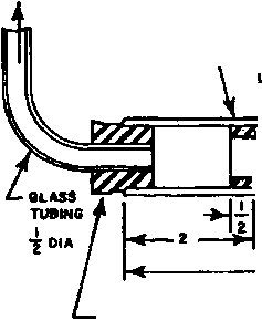  GLASS CLOTH DIAPHRAGM FILTER-GLASS WOOL CLOTH ROLL AMD INSERT GLASS TUBE t./4 ID RUBBER STOPPER DIMENSIONS (IN MCHES) ARE FOR GUIDANCE PURPOSES. FIGURE 509.3-1. SALT SOLUTION RLTER. TO NOZZLES 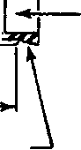 LARGE HOLE RUeSER STOPPER SALT SOLUTION RESERVOIR (REF) FLOW FILTER FIGURE 509.3-2, LOCATION OF SALT SOLUTION FILTER, II-2 PREPARATIOH TOR TEST 11-2.1 Prgliaalnarv stgng. Before initiating any testing, determine the required test conditions (See 1-3.2). 11-2.1 Preparation of jalt solution. The salt xjsed for this test shall be sodivai chloride containing (on a dry basis ) not more than 0.1 percent sodium iodide end not uDre than 0.5 percent total ispisities. Thiless otherwise specified, a 5 1.1 percent solution shall be prepared by dissolving 5 parts by weitfit of salt in 95 parts by weight of water. The soliition shall be adjusted to, and nmintained at, a specific gravity (figure 509.3-3) by using the measured teB>erat s>e and density of the salt solution. Soditsa tetraborate (borax) may be added to the salt solution as a pH stabilization agent in a ratio not to exceed 0.7g soditaa tetraborate to 75 liters of salt solution. The pB of the salt soluticai. as collected as fallout in the exposur>e chaaber, shall be maintained between 6.5 and 7.2 vflth the solution tneratt5>e at (-t-OSF). №ly diluted cheodoal ly pure hydrochloric acid or chemically pure sodiun hydroxide shall be used to adjisit the pH. The pH measurement shall be made electrometically or coloriamtrioally. II-2.3 rbat *> T. operation verification. Unless the chanber has been tjsed within five days, inrasdiately before the test, and with the expcsis chasber espty. adjust all test paraseters to those required for the test. Maintain these conditions for one 24-hour period. Continuously monitor all test parameters to verify that the test chanber is operating н*орег1у. 11-2.4 Pretest standard anbient checkout. All items reqtdre a pretest ehecout at room ambient ccnditioriS to provide baseline data. Crxiuct the checkout as follows: Step 1. Prepare the test item in its required configuration in accordance with General Baquirements. 5.2.2. Step 2. Record the room aabient conditiona. Step 3. Ccnduict a conplete vlsval examination of the test ibmm wdth attention a. High-stress areas. b. Areas <iere dlssladlar nmtals are in contact. C-. Electrical and electronic coqponents - especially those having closely spaced, unpainted. or exposed circuitry. d. Metallic surfaces. e. &iclosed volvnss where condariSaticn has occiirred or nsty occur. MTL-STD-eiOE U JULY 1989 CONCENT1UTI0N 4%NeC! g%WeC! S%NeC!
1.020 1.025 I.030 1.035 SPECIFIC GRAVITY < 1.040 1.045 FIGURE 509.3-3. VARIATIONS OF SPECIFIC GRAVITY OF SALT (NoCi) SOLUTION WITH TEMPERATURE, 509.3-9 f. Conponents or surfaces provided with coatings or surface treatments for corrosion protection. g. Cathodic protection systens; mechsnical systens subject to maiivmetion if clogged or coated with salt deposits. h. Electrical and thermal insulators. №jrE: Partial or conplete disassembly of the test item should be considered if a conplete visual examination is required. Care nust be taken not to damage any protective coatings, etc. Step 4. Document the insults. (Use photographs, if necessary.) Step 5. Conduct an operational checkout in accordance with the proved teat plan. Step e. Record the results for conpliance writh Qeneral Requirement, 5,2.1. Step 7. If the test item meets CSeneral Requirements, the approved test plan, or other applicable docunants, proceed to step 1 of the test procedure below. If not, resolve any problens and restart the pretest standard anbient checkout at the most reasonable step above. II-2.5 Preparation of the test IteaL. a. The test item shall be given a nanimun of handling, particularly on the significant sxjrfaces, and will be prepared for test imnediately before exposure. Vnlmee oih@rwie@ specified, tsst iteoe Shall be ires of surface contaiainaticn suc as oil, grease, or dirt, bich could cause a water break. The cleaning methods shall not include the use of corrosive solvents, solvents which deposit either corrosive or protective films, or abrasives other than a paste of pure magnesiun oxide. b. Arrange the test item configurations as specified In the test plan. c. Insert the test item into the test charrber (General Ssquirensnts, 5.2.2). II-3 PBPCEDUREI - AGGgtAVATED SCBg TMra step 1. Adjust the test chanber tenperature to 35°C (95 F) and condition the test item for at least two hours before introducing the salt fog. Step 2. Continuously atomize a salt solution of a conpoeition as given in II-2.2 into the test chanber for a period of 48 hours or as specified in the test plan. 1/ During the entire exposure period, the salt fog fallout rate and pH of the fallout solution shall be measured at least at 24-ho\ir intervals. 2/ Fallout shall be between 0.5 and 3 ml/80cni?/hr. Step 3. store the test item in a standard airbient atmosphere for 48 hours, or aa specified in the equiinent specification, for drying. Step A. At the end cf the dryir.g period, unless ctherrise specified, the test item shall be operated and the results docunented for conparison with the pretest data. Step 5. The test item shall be visually inspected in accordance with the guidelines given in II-2.4. If necessary to aid in examination, a gentle wash in rusming water not агтвг than 38C (100 F) may be used. П-4 тмрптаит1011 JO gg BggQlgg? a. Test item Identification (manufacturer, serial number, etc.). b. Previous test methods to which the test item was subjected. c. Results of each visual examination and performance checkout performed on the test item. d. Areas of the test item visumlly and functionally examined and an explanation of their inclusion. 6. Areas of the test item not visually and fmctionally examined and an explanation of their exclusion. f. Test dianber operational information (interruptions, time schedule, etc.). g. Test variables: (1) Salt solution pH. (3) Salt solution fallout rate (ml/cm/hr) . (4) Resistance of Initial water and type of water. h. Preliminsry failiire analysis. I/ (Cycling periods of 24 hours each (wet and dry) may be required instead of constant wetting for 48 hours or longer. 2/ More frequent intervals are recomnended. If fallout quantity requirements are not mst, that interval must be repeated. 1 ... 11 12 13 14 15 16 17 ... 43 |
||||||||||||||||||||||||||||||||||||||||||||||||||||||||||||||||||||||||||||||||||||||||||||||||||||||||||||||||||||||||||||||||||||||||||||||||||||||||||||||||||||||||||||||||||||||||||||||||||||||||||||||||||||||||||||||||||||||||||||||||||||||||||||||||||||||||||||||||||||||||||||||||||||||||||||||||||||||||||||||||||||||||||||||||||||||||||||||||||||||||||||||||||||||||||||||||||||||||||||||||||||||||||||||||||||||||||||||||||||||||||||||||||||||||||||||||||||||||||||||||||||||||||||||||||||||||||||||||||||||||||||||||||||||||||||||||||||||||||||||||||||||||||||||||||||||||||||||||||||||||
|
© 2026 AutoElektrix.ru
Частичное копирование материалов разрешено при условии активной ссылки |