 |
 |
 |
| Главная Журналы Популярное Audi - почему их так назвали? Как появилась марка Bmw? Откуда появился Lexus? Достижения и устремления Mercedes-Benz Первые модели Chevrolet Электромобиль Nissan Leaf |
Главная » Журналы » Preparation instrucnons requirements 1 ... 13 14 15 16 17 18 19 ... 43 MIL-STD-SlOE U JULY 1989 RETURN AIR 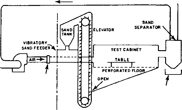 VARIABLE TEMP. SPEED CONDiTiONiNG FAN COIL SAND COLLECTOR NOTE= THE LAYOUT OF THIS SYSTEM IS NOT DRAWN TO SCALE; IT IS INTENDED TO ILLUSTRATE THE ARRANGEMENT OF THE COMPONENTS.THE SPEC! FICATIONS OF ALL COMPONENTS ARE NOT PROVIDED IN THIS TEST DESCRIPTION. THEY MUST BE CALCULATED BY THE ORGANIZATION SUPPLYING THE COMPONENTS. INDUSTRIAL VENTILATION. A MANUAL OF RECOMMENDED PRACTICE WILL PROVIDE DATA AND GUIDANCE FOR DESIGNING THE REQUIRED EQUIPMENT FIGURE 510. 3-2. Blowing sand test facility (horizontal flow) №ПЮО 510.3 5l0.3-ii c. Dehvnidif ication, heatins, шпа coo I ing of ehasber test voluas air for CHsntFol ef test conditions sliall be achieved by aaethods that do not alter the chemical composition of the aiir, aand, or water vapor within the chanber test volume air. d. Test facility design considerations. (1) The vibratory or Screw type sarid feeder shall be controlled tc emit the sand at the specified concentrations. The feeder shall be located in such a manner as to 1пвш^ that the sand is uniformly in suspension in the air stream when it strikes the test item, to sinulate the sane effects as in the field. NOTE: Uniform sand distribution is usxially easier to obtain when the sand-air mixture is directed domward, as in figure 510-3-1. (2) Becatee of the extremely abrasive characteristics of blowing sand at high velocity, it is not reconnended that the sand be recirculated through the fan or air conditioning equlpnent. Instead, it should be separated from the air downstream from the test chanber in a sand separator, collected in a separate receiver, and reintroduced into the sand tank or hopper. Тпл fan should recirculate only the Bwid-iree conditioning air. NOriE: The sand collected in the separator may be reused for other tests if, after analysis, it still conforms to the requirements of I-3.2d(2) of this method. II-l.2 Controls a. Test parfgrgt-ffrgi uiiess otherwise specified in the requirements docunent, tenperature and relative hunidity measin!>ements made during testing shall be continuous if measurements are in analog form, or at intervals of one every 15 minutes or less if measurements are in digital form. Al 1 instrisnentation used with the test chanber shall be capable of meeting the accuracies, tolerances, etc., of General Requirements, 5.1.1 and 5.1.2. Any slgnlfleant change cf the test item tenperature or chanber conditicr.s shall result in the t-est it m being reestablished at the required environmental conditions before continxjation. b. Relative hWtdtW Relative huaiidity in the test section shall be less than 30 percent throughout the condix;t of the test. c. Test variables. The test variables (tenperature, air velocity, and dust ccncentratioa) shall be omtinuouely monitored during the test. Hunidity shall be verified Just before or during each test. II-1.3 Test interruption. (See Gteneral Requlremente. 5.2.4). a. Undertestnterruption. The abrasion, penetration, and collection of dust are cumulative effects that are not affected by interruption. The test item shall be reestablished at the prescribed tenperature and the test continued from the point of interruption. b. Overtest interruption. Any interrvption that results in more extreme exposure of the test item than required by the equipraent specif ications should be followed by a conplete physical examination and operational check (where possible) before continuation of testing. If a problem is encountered, the test should be reinitiated with a new test item. II-2 PREPARATION FOR TEST 11-2.1 Preliminary steps. Before starting any test: a. Determine from the test plan which test procedure is required. c. Operate the test chanjber without the test item to make sure it is working properly. II-2.2 Pretest standard anfcient checkout. All test items require a pretest checkout at standard ambient conditions to provide baseline data. Conduct the pretest checkout as follows: Step 1. Position the test item in the test chanber as near the center of the test sections as practicable. The test item shal 1 have a mininun clearance of IS cm (6 inches) from any wall of the test chanber and from any other test item (if more than one item is being tested). Orient the test item so as to expose the most critical or vulnerable parts to the sand or dust Stream. NOTE: The orientation of the test item may be changed during the test if required by the test plan. Step 2. Prepare the test item in its operational configuration in accordance with General Requirements, 5.2.2. Step 3. Stabilize the test item at standard anbient conditions (Qeneral Reqvu.remente, S.la). Step 4. Condxxrt a conplete visual examination of the test item with special attention to sealed areas and minute openings. IfEraOD 510.3 Step 5. DociJssnt the z>es\ilts. Step 6. Conduct an operational checkout in accordance wath the approved test plan. Step 7. Becord results for conpliance with General Beqiiirements 5.2.1. Step a. !f the t-est it-era operates satisfactorily, proceed to step 1 of the test procedure. If not, resolve the problem and restart at step I of pretest checkout. II-3 PPOCSPUBES i 1-3.1 ?i4>cedure I. - BiowinK dust. The 1о11о п.пв test ргосеаш^ provides the basis for collecting the necessary information concerning the test item in a dust-laden environment. Step 1. With the test item in the chanber. adjxjst the test section tenperature to 23°C (73°F) and the relative hunidity to less than 30%. (Maintain less than 30% relative hunidity throughout the test.) Step 2. Adjust the air velocity to the required value, determined from the test plan. Step 3. Adjust the dust feed control for a dust concentration of 10.6 +7 g/nf (0.3 + 0.2 g/ft). Step 4. Ibintain the conditions of вЬтрв 1 ttai 3 for at least six hows. Step 5. Stop the dust feed, reduce the test section air velocity to that requiired to naantaln tbe climatic conditions, and adjust the tenperature to that determined from the test plan. Step 6. Ilaintain the step 5 conditions at least until stabilization. Step 7. Adjust the air velocity to that used In step 2 and restart the dust feed to maintain the dust concentration as in step 3. Step 8. If required, operate the test item in accordance with the 4>proved test plan. Gontinue the ex;x>sure fcr at least six hoiirs. Step 8. Turn off all chanber controls and allow the test item to return to standard anbient conditions. Step 10. Bemove accunulated dust from the test item by ortwhing. inping, or shakir.g, tskir.g care to avoid intrcduction of additicrAl dust into the test item. Do net remeve dxet by either air blast or уасиш eleMiirig. Step 11. Operate the test item in accordance ith the approved test plan. Step 12. Docvnent the results. Step 13. Inspect the test item giving special attention to bearings, grease seals, lubricants, etc. Step 14. Docunent the results. II-3.2 Procedure II - Blowing sand Step 1. Adjust the chanber tenperature to the high operating tenperature of the test item and saintain until tesperatuB>e stabilization cf the test item is achieved. Step 2. Adjust the air velocity to that required by the test plan. Step 3. Adjust the затк! feeder to obtain the sand concentration specified in the test plan, depending upon the application of ths tsst item. Step 4. Maintain the conditions of steps 1 through 3 for the duration specified in the test plan. Step 5. If operation of the test item during the test is required, perform an operatior,al test ef the item durir.g the last hour of the test and doc\jnent the results. If not, proceed to step 6, Step 6. Turn off all chanber controls and allow the test item to return to standard anbient conditions. Bemove accumulated sand from the test tnit by brushing, vuping, or shaking, taking care to avoid introduction of additional sand into Uie test unit. Step 7. Conduct an operational checkout of the test item in accordance with the approved test plan. step 8. Docvment the results. Step 9. Visually inspect the test item Iccki.ng for abrasion and cleggir.g effects and any evidence of sand penetration. Step 10. Conpare these data with the pretest data. II-4 IKFOiagVTION TO PE SEC0RDE3? a. Test item identification (menufacturs, serial nunbers, etc.). b. Previous test methods to which the specific test item has been subjected. c. Orientation and any change in orientation during test. d. Beaulte of each performance check (pretest, during test, and post-test). e. ViStsthsr the second e-hour test sas performed inanediately after the test item stabilized (see step 6 of amall-partiele procedure). f. Values of the test variables for each section of the test. g. Results of each visual Inspection. h. Duration of each section ef test. heraoD 510.3 ШЬ-8Т1>-810Е 14 JULT 1080 fnj> ngrggMrMTug Tg pSpggDnB AND TggT QQjjfilTPm NOTE: The tailoring prooess as described in section 4 of this docunent should be used to detenaine the appropriate tests and test variables. a. №pIication. This method applies to all militwy items desisned for use in or near flight vehicles, ground vehicles, cr equipment used tc naintain fxiel-handlir.g or fuel-using vehicles. b. Bestrictions. None. c. Sequence. It is recommended that the items used in this test first undergo vibration and/or tenperature testing. Vibration and tenperatiire stresses may i>educe the effectiveness of seals, thus producing f laasable atinosphere se.nsitivitie5 net observable on untested items. d. Test variations. The test variables are tenperature, pressure, humidity, test item configuration, and fuel-vapor mixture. SiETHDD 511.3 EXPLOSIVE ATMDSPHERE SECTION I I-l fWrCm......................511.3-1 1-2 ENVIBONMENTAL EFFECTS...............511.3-1 1-3 GUIDELINES FOP. DETEJaGNINS TEST PROCEDURES AND TEST CONDITIONS .......... 511.3-1 1-4 SPECIAL CONSIDERATIONS ............... 511.3-5 1-5 REFERENCES.....................511.3-5 SECTION II II-l APPARATUS.....................511.3-7 II-2 Pra JffiATION FOR TEST................511.3-7 II-3 PROCEDURES.....................511.3-8 II-4 INFOHMATIOM TO BE RECORDED.............511.3-10 SECTION I I-l IllwrOSE. Thie teet le performed to demonstrate the ability of equipment to operate in flammable atmospheres without causing an explosion, or to prove that a flame reaction occurring % lthin an encased equipment will be contained and will not propagate outside the test item. 1-2 ЕНУХВОМЦрТ], FKHLlS. Low levels of energy discharge on electrical arc from devices ss siaple as pocket transistor radios can ignite mixtures cf fuel vapor and air. A hot spot* on the surface of a hermetically sealed, appazntly inert equipment case caui ignite fuel vapor and air mixtures. Fuel vapors in conpartments can be ignited by a low energy discharge like a spark from a shorted flashlight cell, switch contacts, etc. 1-3.1 Choice of test procedures 1-3.1.1 Procedure I - Squtpnent operation ir.flaigaableatngHphere. This procedjre is applicable to al 1 types of sealed and unsealed eqxiipment. This test evalxjates the ability of the test item to be operated in a fuel vapor-laden environment tvithout igniting the environment. 1-3.1.2 rrocedvs ii - Explosion containaent. This ргосваш е is used to determine the ability of ths tsst itams case or other snclosures to contain an explosion or flame that is a result of an internal equipraent malfunction. 1-3.2 Choice of test conditions. The explosive atmosphere test is a conservative test. If the test item does not ignite the test fuel-air mixture, thex>e is a low probability that the item will ignite fuel vapor mixtures that can occur in actual use. Conversely, the ignition of the test fuel-air mixture by the test item does not isean that the test item will al nys ignite fuel vapors that оссш* In actual deployment. 1-3.2.1 Fuel for test. The fuel recomnended for explosive atmosphere testing shall be the single-conponent hydrocarbon n-hexane (i.e.. normal hexane). This fuel is used because its ignition properties for f laiiSisable atmosphere testir,g ar-s equal tc or better than the Similar properties of both IQ0./130 octane aviation gasoline and JP-4 Jet engine fuel. Optinun mixtures of N-hexane and air will ignite from hot-spot tenperatures as low as 222.8°C (433°F) while optiniLm JP-4 Jet engine fuel-air mlxtis>es require at least a 229.40 (445**F) tenperature level for autoignltlon and 100/130 octane aviation gasoline and air requires 440.6°C (825 for hot-spot ignition. Miniioura Spark energy inputs for ignition of optisaum fuel vapcr and air Siixturas are essentially the saaie for n-hexsue and for 100/130 octane aviation gasoline. Mush higher mininum spark energy input is required to Ignite JP-4 Jet engine fuel and air mixtures. 1-3.2.2 Fuel vapor jslxture. The fuel vapor mixture used in the explosive atmosphere test shal1 be homogeneous. 1-3.2.3 Test tenperature. The fuel vapor mixture is heated to the highest anbient air tenperature at which the test item is required to operate during actual deployment. Heating the anbient air to this tenperature gives the fuel vaor/air mixture its greatest likelihood for ignition. All testing should be done at this meixinun air tenperattjre. For forced-air-cooled equipment, the test tenperatts e shall be the highsst teaperature at which equi; asnt perfcmancs can be evalijatsd in the absence of cooling air, 1-3.2.4 Quantitv of fusl. ttilsss otherwrise specified, the fuel used shall be n-hexane, either reagent grade or 05 percent. The 95 percent n-hexane fuel actually is nearly 100 percent hexane, because the remaining 5 percent consists of hexane isomers. Fuel weight calculated tc total 3.S percent by vcluiue cf ths test atasssphers represents 1.8 stQlchioHsetrlc equivalents of n-hexane in air, giving a mlxtiB** needing only mininun energy for ignition. a. Required information to determine fuel weight: (1) Chamber air tenperature during the test. (2) Fusl tsspsraturs. (3) Specific gravity of n-hexane (see figinre 511.3-1). (4) Test altitude: e.g., 6100 meters (20,000 feet). Atmospheric pressure in pascals: 46.6 kPa (6.76 psia). (5) Net volume of the test chanber: free voluss* less test Item displacement expressed in liters or cubic feet. b. Calculation of the voltme of liquid n-hexane fuel for each test altitude: (1) In inetric uriitB: Volune of 95 percent n-hexane (ml) = [net chanber vol (Ijters)] [chamber pressure (pascals)j. (396 X 10 ) [chanber tenp (K)J [specific gravity of n-hexane] Volune of 95 percent n-hexane (ml) * Lost <?tHMrber vol IltIl [сДццфег pregsyre (pga) ] (45.89) [chanber teap (H)] iSpeciiic gravity of n-hexane] 1-3.2.5 Effect of hunlditv on flanmable atmosphere. Humidity is always present in an explosive atniosphei>e test. The effect of hunidity vpon the fuel-air mlxtin*e percent conposltlon need not be considered In the test if the anbient air dewpoint is 10°c (50**F) or less because this concentration of water vapor only Increases the n-hexane fuel concentration from 3.82 percent to 3.S5 percent of the test atmosphere. If the atscspheric presaxire is cycled from 1525 ssters (5Q0Q ft.) above the test level to 1525 meters below (a 34-percent change in pi>essure), the volune of n-hexane will decrease from 4.61 percent to 3.08 percent. This decrease will conpensate for the fuel eitrichment effect that results from mter vapor dilution of the test air sipply. 1-3.2.6 Altitude sigLilation. The Bsxintsi altitude at v*iieh the test tins will be expoeed to fuel vapors d\n>ing operation shall be the maximun test altitude, unless otherwiee specified. If the test facility is not at sea level and the test is for shipboard equipment, the test chanber shall be pressurized to sinulate sea level, unless otherwise specified. КЕТЮО 511.3 1 ... 13 14 15 16 17 18 19 ... 43 |
|
© 2026 AutoElektrix.ru
Частичное копирование материалов разрешено при условии активной ссылки |