 |
 |
 |
| Главная Журналы Популярное Audi - почему их так назвали? Как появилась марка Bmw? Откуда появился Lexus? Достижения и устремления Mercedes-Benz Первые модели Chevrolet Электромобиль Nissan Leaf |
Главная » Журналы » Preparation instrucnons requirements 1 ... 14 15 16 17 18 19 20 ... 43 0.67 0.65
1°c 20° с 30 С 35с l4l F 50°F 59°F 68-F Tpnpereture 77Т 86 F 95*F KETKOD 511.3 FIGURE 511. 3-1. Sp#elflo gravity of п.Нежапе. 1-4 SPECIAL COJEIDBtATIOH 1-4.1 Test Interruption. If there is an unscheduled tst interrxtion, the ehanfcer shall be rettJB?ned to gro\JBr>d level and pursed to remove the flamnable atmosphere. The test shall be reinitiated from the point of interruption using the sanm test item. 1-4.2 Overtest. Any interrviption in the test that results in a more extreme exposure of the test item than required by the equipment specification should be folloiSBd by a coizplets physical inspection of the test item and an operational cheek prior to continuation of test. An engineering jxjdgnsnt shal I be made lAether to continue testing with the specific item given the overtest, to obtain a new item, or to consider the test conpleted. 1-4.3 Failure analysis. All failures (see 1-4.4) and incidents iere the test items do not nmet the equimnt operating requirenents shall be analyzed to determine the cause and Inpact of such occurrences. Corrective actions shal1 be proposed or inplenented ая required to meet equipment performance requirenents. 1-4.4 Fajlyre criteria a. Proc-edur-e I Ignition of test fuel vapcr and air envirennsnt ccnstitutes failure of the test. b. Procedure II - Propagation of flame to, or ignition of, a flammable atmosphere surrounding the test item when the test atmosphere within the enclosure or case of the test item is intentionally ignited constitutes failure of the test. 1-4.5 Susaaery of information required. The following information is required in the test plan for the conduct of the tests of Section II: a. Test altitudes. b. Test tesqper-at-ures. c. Fuel voluRie and/or weight. d. Test item configuration. 1-5 BEFgppiCgg a. Haskin, W.L, Explosion-Proof Testing Teehniques. 1963. ASD-TDR-62-1081-. DTIC msiber AD-400-483. b. Zabetakis, M.G.. .A.L. Furno, and G.W. Jones. Minirainn Spontaneous Ignition Tenperatures of Cowbustibles in Air. industrial and Engineering chemistry 46 (1954), л к f о-i6i f а. УЕтХ> 511.3 511.3-е c. Whshburn, E.W., ed. International Critical Tables of Nurorical Data. Chemistry, and Technology. Vol. III. New York: National Research council/McGraw-Hill. 1928, pp27-29. d. Kvschfea, J.M. Sxasary of Ignition IVopertieg of Jet Fuelg and Other Aircraft Confcustible Fluids. 1975. AFAFL-TR-75-70, pp9-14. DTIC nurnber AD-A021-320. e. A2TM E 380-79. Standard for Metric Practice. Step 4. A thermocoiple shall be placed on the most massive conponent of the test item. Step 5. At least two thermocouples shall be placed on the inside of the test chanber walls. n>ese thermocotples (from steps 4 and S) should be Instrisnented for monitoring outside the test cdianber Ьеп the chanber is sealed. 11=2.2 Procedure II - Explosion eontaiPit- Step 1. The equipment, or a model of the equipment of the same volune and configuration, shall be placed within the case and the case installed in the explosion chanber. METHOD 511.3 EXPLOSIVE ATMOSPHERE TEST SECTION XI II-l APPitftATUS. A test chainber capable of producing the required test conditions shal 1 be used. Appendix A describes one type of chanber that nay be used. II-l.l Fuel. Ibless otherwise specified, n-hexane (i.e., norsal hexane) of at least 95 percent pwity Shall be ied. 11-2 PREPARATION FOR TEST. The test item shall be prepared in accordance with Qeneral Requlremente, 5.2.2. II-2.1 Procedure I - Operation in explosive atmosphere Step 1. The test item shall be Installed in the test chanber in such a nanner that normal electrical operation is possible and mechanical controls may be operated throxjgh the pressure seals from the exterior of the chanber. External covers of the test Itetti shall be removed or loosened to facilitate the penetration of the explosive mixture. Large test items may be tested one or more units at a time by extending elecU>ieal eonneetiws throi the cable port tc the r-enairrfisr cf the associated equipsant located externally. Step 2. The equiinent shal 1 be operated to determine it is functioning properly and to observe the location of any sparking or high tenperature conponents which could cause an explosion. Step 3. Mechanical loads cn drive assesblies and servonschanical end electrical loads on 8 ltches and relays m.ay be slnulated vben necessary if proper precaution is given to duplicating the normal load in respect to torque, voltage, current. Inductive reactance, etc. In all Instances, it is preferable to operate the equipment as it normally functions in the ayetmm during service use. Step 7. Perform steps 4 and 5 of II-2.1. II-o PBOCEDUi 11-3 л ProcedTj I - Operation in explpsive atmoaere Step 1. Perform the preparation for test. Step 2. Seal chanber with the test item motsited inside. Step 3. Raise the a.ibient tenperature cf air inside the chasber tc that determined in 1-3.2.3. Whit vntll tenperatures of the test item and test chanber inner walls comes to within ll°C of chanber anbient air tenperature. Step 4. Adjust the chanber air pressure to simulate the test altitude plus 1000 meters, as given in 1-3.2.6. plus adequate additional altitude tc allow for introducing, vaporizing and mixing the fuel dth the air. Step 5. Inject the required quantity of n-hexane into the test chanber as determined by 1-3.2.4. Step 2. Make provision to circulate the fuel-air mixture into the case being tested. In the case of forced-air-cooled equipment, the cooling air oust contain the proper fuel-air mixture. For equipment not using forced-air cooling, it is necessary to drill the case for insertion of a hose from a blower. Take adequate precautions to prevent ignition cf the anjbient mixture by backfire or release of pressure through the simply hose. Any modlfication to facilitate Use introdiistion of i nitable vvpov shall not alter the case internal volisne by more than SX. Step 3. Provide a positive means of igniting the explosive mixture within the case. The case may be drilled or tapped for a spark gap, or a spark gap may be RDunted internally. Points of ignition should not be aore than 0.5 inch from any vent holes cr flams arresting devices, and ss many cf such ignition sources should ba Installed within the case as there are vent holes or flame arresting devices. Where the design of equipment makes this inpractlcal, xjse as many points of ignition as are practical. Step 4. A thermocoile inserted into the ease and attaMd to a sensitive galvanotneter outside the test chaieber may be used to detect ё>ф1ож1опв vnthln the case. Step 5. Insure that the air within the test chanber has a water vapor dewpolnt lower than 10°C (500F). Stsp 6. If the site atmospheric pressure at the test location is less than 833 nitflg, make provisions to pressurize the test ehaafcer to at least 033 sasHg. Grcurtd level pressures referred to in II-3.2 step 5 shall consist of pressures from 633 to 800 mnoHg, inclusive. Step 13. Docunent test results per II-4. II-3.2 Procedure.II - gxplSPn cQptainfflent test Step 1. PerfcFm preparation for the test as given in II-2.2. Step 2. Seal the chasber with the test item inside. Step 3. Baise the anbient air tenperature inside the chanber. Step 4. libit vntil tenperatures of test item and test chanber inner walls come within 11°G of chanber anbient air tenperature. Step 5. C%ange the chanber air pressure to 1500 meters of slnulated altitude above the station anbient pressure (i.e., grovmd level). Step 6. Inject the required quantity of n-hexane into the test chanber to obtain cptisun fuel-vapcr/air sxture at staticn asibient pressure cr as given in 1-3.1.4b for n-hexane. Step 6. Circulate the test atmcsiiere at least three, but not more than ioxir, minxjtes to allow for conplete vaporization of fuel and the development of a hcntcgsneous mixtvBe. Step 7. Operate the test item. Operation shall be continixjus from step 7 through step 9. Make and bi>eak electrical contacts as frequently as reasonably possible. Step S. Slowly increase ths air pressure in the test chan±>er by bleeding air intj the chamber, Sinulate change of altitude at a rate no faster 100 meters per mintite. Step 9. Stop the air pressure change at 1000 meters below test altitude or at grovvtd level, vbichever is reached first. Step 10. Check the potential explosiveness of the air-vapor mixture by atteiK>ting to ignite a sanple of the mixture by a spark-gap or glow plug ignition source having sufficient energy to ignite a 3.82-percent hexane mixtxire. If ignition does not occur, return the chanber to anbient atmospheric pressxire, purge the chanber of the fuel vapor, and reinitiate the test at the most recent test altitude. Step 11. If the lower limit cf sisulatad altitude reached in step 9 is 3000 meters or greater above sea level, reduce the value of the test altitude by 3000 meters. If the station anbient pressxire altitude (i.e., grovnd level) was reached, go to step 13. If the station anbient pressure was not reached, continue to step 12. Step 12. Using the new value of test altitude from step 11, conduct steps 5 II. Step 7. Circulate the test аышйршагв lor at least thrra jt no sore than Isasr minutes to allow for the conplete vaporization of fuel and the develcment of a Ьотэепеош mixttn wthin the test item and within the test chanber. Step 8. Bleed air into the chanber to return the pressure altitude to station ambient pressure (i.e., ground level). Step 9. uiergize the internal case ignition soxsr-cs. Step 10. Confirm the occurrence of an е1ф1о81оп within the test itmn using the installed thernoocovple. If no explosion occiss, purge the chanber and the test item of all air/fuel vapor and return to step 2. Step 11. If the explosion inside the test items case did not propagate to the fuel/air mixturs outside the test item: (a) Bepeat steps 5 through 10 four times if the test items case is not in excess of one fiftieth of the chamber volume, (b) If the test item volise is eфJal to Or ater tJban One-fiftieth of the chamber volune, purge the chamber and test item of air/fuel vapor and repeat steps 2 throi 10 fom* timee. Step 12. Check the potential explosiveness of the air/fuel vapor mixttae by attempting to ignite a sample of the mixture by a spark or glow plug. If chanber sanple does not ignite, purge tbe chanber of all air/fuel vapor mixture, and 4 .. Л-тшЛ. Ф^ш^ шшЛ. О step 13. Document the test resiilts. II-4 INFDBMATICW TO BE BECOBDED a. Test item identification (mar.ofacturer, serial nuiber, etc.). b. Test procedure nuiber. c. Cianber pressts>e and tenperatures at each test point (sinulated altitixle). d. For Procsdurs II, th© locatior.s of glow plugs or spark gaps ir.stalled inside test items. e. For Procedure II, the energy requirement for the glow plug or spark gaps for operation. f. The quantity of fuel required at each test point. g= The off/on cycling rate for !# feeefe equipeent. APPENDIX A ШГтЬ 511.3 E3£PLC IVE ATK PHE!ffi (ШШт. FLAMMBLE ATMOSPHERE TESTIN9 A-1 This appendix deacrlbee one test wnber capable of producing the f laimable atnoephere conditiona required for this test nethod. A-i.i Goimonent ошрЬв. The facility shall consist preferably of a steel test chasber and associated рифе, ignition systesi. VjsI sstering systesi, power source, end any other equipaaent necessu to neet the requirenents for test naethod 511.3 for f lamoable atmosphez testing. A-1.2 DesKn and construction. The explosive atnosphere testing facility shall be a portable, self-contained unit or a pemanent installation consisting of a well-lighted test ehaober equipped nth a stem for mixing and circulation of explosive atr/fusl vapor mixtures, a msans of ignition of alr.vapor mixture, an explosion relief valve system (flgxire Al is a drawing of a differential presstjre explosion-relief valve), and a vacuun puqp-to permit the simulation of altitude. Adequate controls and instrunentation shall be provided. The facility shall be aesenbled on a chassis or frame and could be mounted on pneumatic-tired wheels for portability. The desi may conform in general to figure A2 and shall be capable of conpliance with ths requirements cf this method. A-1.2.1 Chanber. A practically sized test chanber should provide a minimum clear working space three feet in diameter and five feet long and should be capable of maintaining any desired pressijre altitude within performance limits specified in A-1.3.5. A-1.2.1.1 Qpenirjis Ths chasber shall have pressxjre relief valves and shall be enable of Gonformanee writh the м>р11еаЬ1е req\ilremente of A-1.3. Pressure-tight Jacks for transmission of power to and from the test item shal 1 be provided, together with openings for the insertion of sealed nachanical controls, as required. Observation windove shall be provided in both sides of the chanber. A-1.2.1.2 Floor. A removable floor, having a mininun area of 0.75 square meter (8 aq>.ere feet) and capable of supporting 4880 kilograas per square meter (100 pouvis per square foot) within the chariber. A-1.2.1.3 LilOttlwl. The test chanber shall be lighted with two 150-watt lanps of explosion-proof design, one located at each end of the chanber, to provide imiform illxjmination. A-1.2.1.4 Stuffing-boxes. Two stuffing boxes shall be provided to facilitate ths penetration of cabling connectors and control shafts. Low Pressure ReJief Velve for Air Pressu-e Release and Control of Main Valve Aetion Wnen a negative PrtsEur? Does !kjt Exist Within the Explosion Facility Needle Valve for Manual Control of Facility Pressure Release Valve 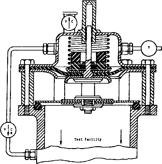 eedle Valve For Autosetic Control Of Facility Pre eure Release Valve This Valve is Designed for the Release of Internal Facility Pressure tar the Controlled topllcatlon of a negative Force vfaich Lifts the Valve Off its Seat vhen an Explosion Occura vithin the Test Facility FIGURE Al. An emaple of differential pressure etploaion-relief Talve. ы < (Л flemovable Shelf Hinff >d Access Door в PimctratHorie (U esich tide) ahnll be prorlded for 250 Control Rode. --j PeiMtratione shall l e provided with Packing Glands as required Explosion-Pressure Release Systitm Clbserration Windows Control and Instrunwfnt Panel (Electrical Panel Other Side) Heirovable Panels <A11 Sides) 2 liich .?>0 Pipe Penetrations shall be provided for: Compressed Air, Vacuum, nd Hydrnul.ic Fluid All Equipment Necessary to Produce, Conditions Speciri !d shall be installed below th Test Section Facility shall be leHigned to Wlthatand TranepDrtation by Sling or Forkllft Dimensions in Inches 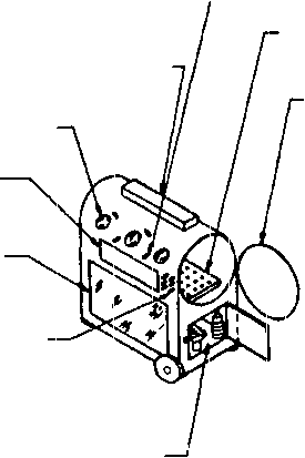 36 Min 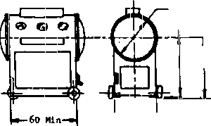 5-1 Appro X 9--- I - 36 Approx FIGURE A2. atiaiibfii:..LUMULiLiJUiauhfirAJjuUiiK. ai VO .I 1 ... 14 15 16 17 18 19 20 ... 43 |
|
© 2026 AutoElektrix.ru
Частичное копирование материалов разрешено при условии активной ссылки |