 |
 |
 |
| Главная Журналы Популярное Audi - почему их так назвали? Как появилась марка Bmw? Откуда появился Lexus? Достижения и устремления Mercedes-Benz Первые модели Chevrolet Электромобиль Nissan Leaf |
Главная » Журналы » Preparation instrucnons requirements 1 ... 16 17 18 19 20 21 22 ... 43 TABLE 512.3-1, Wbter pressures at various deptha.
NOTE: The equivalent head of sea veter is 0.975 times the head of fresh vater for the sams pressvoe difference. a. Iteterpenetration. Determine which of the following is applicable: (1) Unconditional failure. Any evidence of water penetration into the test item enclosure following the inmersion test shall be a basis for failure. (2) Acceptable water penetration. №t@r penetration of not mors than 4 cs? per 28,000 cm (1 ft) of test item enclosure 2/ shall be acceptable, provided the following conditions are met: (a) The water has no inmediate effect on the operation of the test item. (b) The teat item in its operational configwatlon (transit.storage case open or renoved) shall successfully conplete the induced tenperature/humldity (procedure II) of nethod 507.3 for the geographical area in vihich it is designed to be deployed. b. Operational fai 1 ure. Failure of the test item to satisfy its ivmetlonal reфJiгeп!eпt shall constitute an irrBisrsion test failure. c. Safety. The test item nust be safe to operate following the imnersioh test. 1-4.2 Additional considerations a. Wien testing a shipping/storage container or transit case without the test items enclosed, all dunnage, packing, padding material, etc, that may absorb Mater shall be removed, if possible, before the test. 2/ This quantity of water (4 cm) is approximately the quantity required to raise the relative humidity of one cubic foot of air from 50% at 21°C (70°F) to saturation at 49°C {120°F). The 49°C val-oe is realistic for equipment expoged to high-tenperatiffe and solar-radiation effects. 512.3-4 - * ц , . .- X a. ML-S-55286, Shelter. ElectricalVjuipment S-280( )/G b. MIL-S-55541. Shelter. Electrical Equlpnent S-250( )/G КЕТЮО 512.3 b. Extreme caution must be exercised when using the test item handles, protrusions, etc., to pull the test item under the water. This could produce unrealistic stress and leakage into the test item. 1-4.3 Stmmarv of test inforrnation recruired. The following information is required in the test plan for adequate conduct of the tests of section II: a. Test procedure nuober. b. Physical size of the test item (to determine test facility requirements). G. Tiedo an precautions (to prevent urirealistic stress). d. Test item configuration. e. Conditioning tenperature and duration. f. Covering/insBsrgion depth. g. Duration of immersion. h. Mditional guidelines. METHOD 512.3 SECTiai II II-l APPARATUS II-l.l Test-facility a. The required test apparatus should ir.clixle a water container that can achieve a covering depth of Im (3=3 ft) (or other required depths) of water over the tDpenaost point of the test item and maintain the test item at that depth. Also required is a chamber or cabinet capable of heating the test item to the required tenperature. b. A water-soluble dye such as fluorescein may be added to the mter to aid in locating and analysing п1ег leaks. 11-1.2 Controls a. The tenperature of the water shall be 18° +.10°C (64° +18°F). b. The teiqperatme of the test item shall be 27° l.2°C above the teiEper-ature of the water. c. The temperature of the water shal 1 not change more than З^С (SF) throughout the duration of the test. II-1.3 Тезt interruption (See General Requirements. 5.2.4) a. Undertest interruptions. An interruption that results in less severe conditions than specified should be treated as a no test*. The test item should be dried and stabilized at standard ambient conditions and the entire test procedure repeated from the beginning. Any failure discovered during an tmdertest condition should be treated as a failure. b. Overtest interruptions. Any interruption that results in more severe conditions than specified should be followed by a conplete examination of the test item and an operational check (vhere possible) before continuation of testing. If no problem is evident, the test should be restarted, preferably ith a new test item. II-2 PREPAPATICHi FOR TEST II-2.1 Preliminary steps. Before intitiating any testing, determine from the test plan: a. The ininersion depth and time and, if applicable, the preheat tenperature and duration. ШТНОО 512.3 b. The овала to be used to secure the test item at the appropriate depth. c. The test item configuration. II-2.2 Preteat checkout. All test iteme require a pretest checkout to provide bsLsellne data. Conduct the checkout as fol lows: Step 1. Prepare the test item in accordance with General Requlraments, 5.2.2. Step 2. Examine the test item for evidence of free water. If ariy is ioxsid. dry tha test item cospletely before continuing. Step 3. Visually exaaiine the test item, giving special attention to areas around seals. Step 4. Document the resijdts. Step 5. CcPiduct an operational check in sccrdance with the requirements dccuaint. Step e. Docunent the results. Step 7. Proceed to step 1 if no problems are loistd; otherwise, correct the problem and restart at step 1 above. II-3 PB0C3>URE I - Baaicleakajte Step 1. Three times, immediately before the test, open and close (or remove and replace) any doors, covers, etc.. that would be opened during normal use to insure that any seals are zvnctioning properly and are not adhering to the sealing вш ! aces. Step 2. Condition the test item as in 1-3.2b. The test items sealed areas ( Aiere practicable) shall remain open throughout the heating cycle. Also, equipment occasionally incorporates valves or venting devices vAiich nay or nay not be opened in nornal service use. If the test item incorporates such a device, it should be opened throughout the heating portion of the test. Step 3. MBasvs*e and record the iBinerslon wetter teaperature. If not in accordance with II-1.2b, adjust as required. Step 4. Close all sealed areas and valves, assenble the test item in its test configuration and, as quickly as possible, immerse the test item in water so that the ippermost point of the test item is Im ip.lra (3.3 ft 3.0 in) below the surface of the water, or as otherwise required by the test plan. Step S. Measure and record the water tenperature at 30 minute intervals following inmersion of the test item. MIL-ST!>-81< 14 ШЛ 19в& Step 6. The test item shall remain inmersed for 120 ± five minutes. Step 7. Remove the test item from the water. Step 8. №p6 the exterior surfaces cf tha test itw dry, giving special attention tc areas eroistd seals and relief valves. Step 0. If applicable, equalize the air pressure inside the test container by activating any manual valve(s). Step 10. Open Ute test item and examine ше interior and contents for evidence of and qiamtity of lealiage and for ртоЬаЫе areas Ьега the leakage occurred. Step 11. Document the results. Step 12. Conduct an operational check of the test item, if applicable. Step 13. Docvanent the resxuts. Step 14. Соорш^ Uie results with the baseline data obtained in II-3.3. II-4 IMFpRMftTIOW yo pg ffiCORDED a. Test item identification (manufacttarer, serial тмЛвг, etc.). b. Previous test methods to which the test item has been stibjected. c. Amount of leakage into the test item. d. Point(s) of leakage. e. tfeter and test item trpsratures. f. Test item configuration g. Depth of imnersion. n. Dilation of Imersl. 1. Restate of performance checks (pretest and post-test). hSTHOD 513.4 ACCELERATION SECTION I I-l PURPOSE ...................... 513.4-1 1-2 ENVIRONNENTAL EFFECTS...............513.4-1 1-3 GUIDELINES FOR DETmWCNING TEST PBOCEDUKES AND TEST CONDITIONS..........513.4-2 1-4 SPECIAL CONSIDERATIONS ............... 513.4-9 1-5 REFERENCES ..................... 513.4-10 SECTION II II-l APPARATUS ..................... 513.4-11 II-2 PREPARATION FOR TEST................ 513.4-11 II-3 PROCEDURES ..................... 513.4-12 II-4 INFORMATION TO BE RECORDED............. 513.4-13 SECTION I I-l PURPOSE. The acceleration test is performed to assure that equipment can structurally withstand the g forces that are expected to be induced by acceleration in the service environment, and function without degradation during and following exposure to these forces. 1-2 ENVIB0NME3frAL fcjfE.CTS. Acceleration generally increases the forces acting on equipment and the Ьаг^мше used to mount the equipment. An exception is acceleration that induces forces in opposition to gravitation forces, in *iich case the equipment can approach or attain a state of weightlessness emd become reverse loaded in excess of the opposing gravitational forces. The forces induced by acceleration can cause: a. Structural defl@ctior.s that interfere with equipment operation. b. Permanent deformations and fractures that disable or destroy the equipment. c. Broken fasteners and mountiTig hardware that cause equipment to become loose projectiles. d. Electronic circuit boards to short out and circuits to open xjp. e. Inductances and capacitances to change values. f. Relays to open or close. g. Actuators and ether mechanisms tc bind. h. Seals to leak. i. Pressure emd flow regulators to chemge value. KETrlOD 513.4 J . Рифв to cavitate. k. spools in servo valves to be displaceu arid cause erratic and dangerous control systess response. 1-3 GtUIDELIllES FOR DETTERMIWIWG TEST PROCEI>URES AMD TEST COMDITIOMS NOTE: The tailoring process as described in section 4 of this docxsnent lOiould be used to determine the appropriate tests and test variables. a. Ads 1 ication. ТЫв test method is applicable to equipnent and devices tbat are installed in aircraft, helicopters, manned aerospace vehicles, air-carried stores, and ground-launched missiles. b. Restrictions. None. c. Sequence. The high temperature test should be conducted prior to acceleration. d. Test variations. The tests vary in acceleration, axis of acceleration, duration, test apparatus, and on/off state of item. 1-3.1 Choice of test procedures. There are ti-o test procedures. Procedure I (Struct\jral Test) is used to demonstrate that equipomnt will structurally withstand the loads Induced by in-service accelerations. Procedure II (Operational Test) is used to dencnstrate that equipment will operate without degradation during and after being subjected to loads induced by in-service acceleration. Equipomnt to be tested should be subjected to both Procedure I and Procedvire II tests ijnless otherwise specified. 1-3.2 (Д1о1се of test conditions. Acceleration values for individual eqxiipnant items should be obtained from the aircraft structural loads analyses. №en the applicable aircraft is unknown, the values of tables 513.4-1 and 513.4-II and tbe following paragraphs nay be used. For the purpose of these tests, the direction of forward acceleration is always considered to be the direction of forward acceleration of the host vehicle. The test item is tested in each direction along three mutually perpendicular axes for both test procedures. One axis is aligned with the forward acceleration of the vehicle, one axis is aligned with the spanwise direction of the vehicle, and the third axis is perpendicular to the plane cf the other two axes. Figure 513.4-1 shows the six acceleration test directions. TABLE 513.4-1 SintgestedQ levela for Procedure I - Structural teat Test Level Vehicle Category Forssard Acceleration A in gs 1/ Direction of Vehicle Acceleration See Figure 513.4-1 Lateral Fore ! Aft Doiwi Left : Bight
:wir.g/ ISponson Aircraft! Mounted Stores  7.5A 1 9.OA ! 4.9A ! Е.бА ! 5.6A !Fuselege : 5.25A ! 6.OA ! 6.75A i 4.1A : 2.25A : 2.25A : (-GUid-LsiS.c.ed . 8/, 3/ tMLasilee : ! 1.2A : 0.5A ! 1.2A ! 1.2A ! 1.2A ! : I ! ! 7/ ; 7/ ! 7/ 1/ Levels in this colum should be ueed when forward acceleration is unknown. When the foriMBurd acceleration of the vehicle is knoiwi, that value shall be used for A. 2/ Fcr carrier-based aircraft, the adniiiur. valtie to be xjsed for A is 4, representing a basic condition associated with catapult launches. aL For attack and fighter aircraft, add pitch, yaw, and roll accelerations as applicable. 4/ For helicopters, forward acceleration is unrelated to acceleration in other directions. Test levels ar-m based on dsrent and near future helicopter design requiresants. 5/ Mien forward aeeeleration is not !шомп, the high valtje of the acceleration range should be used. 6/ A is derived from tbe thrust curve data for maximum firing tenperature. 7/ Wiere A is the maximun maneuver acceleration. в/ In some cases, the maxlnun maneuver acceleration and the maxlnun longitudinal acceleration will occur at the saras tiras. \№яп this occurs, the test item should be tested with the appropriate factors using the orientation and levels for the maxlnun (vectorial) acceleration. JsETBOD 513.4 TABLE 513.4-II. Suggested G levels for Procediira II - Qpepatlonal taat. Vehicle Category Test Level Forward Acceleration A in gs 1/ Direction of Vehicle Acceleration (See Figure 513.4-1) : Lateral Fore Up : Dowi : Left t Right I Aircraft 2/. 3./ l.OA ! 3.0A ! 4.5A I 1.5A I 2.OA 2.OA S Helicopters 2.0 ! 2.0 ! 7.0 ; 3.0 ! 4.0 ! 4.0
1/ Levels in this colism should be xjsed when forward acceleration is unknown. ben the forwerd acceleration of the vehicle is known, that value shall be used for A. 2/ For carrier-based aiicraft, the miniaui value to be used for A Is 4. representing a basic condition associated wdth cat 9ult launches. 3/ For attack and fighter aircraft, add pitch, yaw, and roll accelerations as applicable. 4/ For helicopters, forward acceleration is lAirelated to acceleration in other directions. Test levels are baaed on current and near futia>e helicopter deaign requlremente. Ъ/ wien forward acceleration is not known, the high value of the acceleration range should be used. 6/ A is derived from the t-hrxst curve data for saxisLss firing testeratis. 7/ Where A is tbe maximLsn maneuver acceleration. 8/ In some cases, the maxinun maneuver acceleration and the maxinun longltxjdinal acceleration wri.ll occur at the same time. When this occurs, the test item shoiild be tested vith the appropriate factors xising the orientation and levels for the naxiBum (vectorial) acceleration. Down 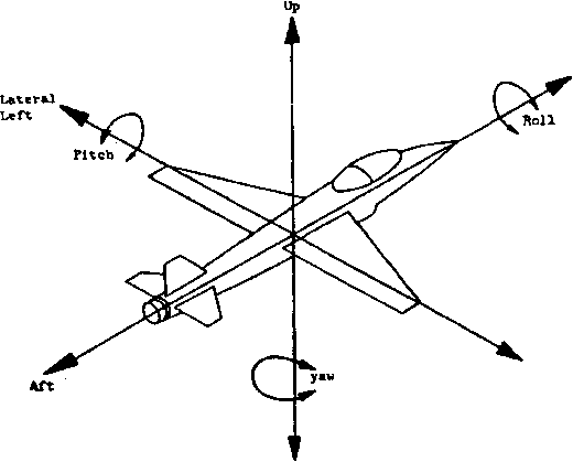 Fore Lateral Right FIGURE 513.pirectlon* of vehicle acceleration 1 ... 16 17 18 19 20 21 22 ... 43 |
||||||||||||||||||||||||||||||||||||||||||||||||||||||||||||||||||||||||||||||||||||||||||||||||||||||||||||||||||||||||||||||||||||||||||||||||
|
© 2026 AutoElektrix.ru
Частичное копирование материалов разрешено при условии активной ссылки |