 |
 |
 |
| Главная Журналы Популярное Audi - почему их так назвали? Как появилась марка Bmw? Откуда появился Lexus? Достижения и устремления Mercedes-Benz Первые модели Chevrolet Электромобиль Nissan Leaf |
Главная » Журналы » Preparation instrucnons requirements 1 ... 19 20 21 22 23 24 25 ... 43 ICL-STD-eiOE 14 JULY 1080 Port Staging Area < (PSA) 375 miles ---------> Corps Storage Area (CSA) 125 miles <-------> Forward Supply Point (FSP) 16 miles Using Unit -> < - 16 miles Trvcks, Semitrailers TviiD-VSieeled Trailers <-------------> TwQ= Sieeled Trailers or KB48 Cargo Carrier FIGURE 514.4-6. Typical Bdssion/iield tranaportation BeenaSrio. 1-3.3.2 Category 2 - Large asseirtolv transport. 1-3.3.2.1 Appl ication. In some cases, it may not be practical or efficient to test large shelters or systems on a shaker. In stjch cases, transportation conditions may be sinulated using the actual transport vehicle as the viraation exciter. Tnm assersfclage may consist of equipment mounted in a truck or trailer, cr equipeasnt mounted in a shelter it>lch le then mounted on a truck, trailer, or dolly set. The exposure consists of traversing the transport vehicle over a prepared test course until the test item has received exposure representative of anticipated deployment scenarios. The assemblage shall be mounted into the transport vehicle for iich it was designed in its deployment configuration. If the asseniblage is to be contained in a shelter, it Shall be installed urithin the shelter in the deployment conflgvs*ation. The shelter should be mounted and secured on the transport vehicle(s) that is normally used for the shelter under actual transport. Provide instrumentation to measure the vertical axis acceleration time history on the shelter floor and at any other locations of ecnseim. 1-3.3.2.2 Test level. The vibration levels and intensities received by the test item during this test are based vpon the course profile and vehicle speeds as specified in procedwe II. VarioLS road surfaces are tc be used, each traversed at speeds *iich will prodjoe the desired vibration intensity. Transport vehicle speeds Ш>е limited either by the vehicles safe operating speed over a specific course profile or by the speed limit-set for the specific course. 1-3.3.2.3 Test duration. The test duration shall be as specified in procedure II or \sitil the test item has received the exposure representative of the anticipated deployment Bcenarios, wichever is loriger. 1-3.3.3 Category 3 -joose cargo transport. 1-3.3.3.1 Application. Ibis test is intended to simulate the unrestrained collision of the test item with the bed and sides of the transport vehicle as well as with other cargo. The loose cargo environment includes conditions experienced by packaged and unpackaged items trarispcrted as vsnsecured cargo cn a vehicle traversing irregular surfaces. The cargo has the freedom to bounce, scuff, or CQlllde wdth other items of cargo or % ith the sides of the vehicle. This environment is simulated in the laboratory by inparting motion to the test item and al lowilng It to collide wdth restraints established wiithin the test setup. The test conditions for this environment are established, to a large extent, by the equipment used to inpart the action, and the arrangement of the restraints as described in procedure III. This test has few tailoring cptior.s and the selection of the test equlTsent oust be based \фоп the desired end result. 1-3.3.3.2 Test levels. The basic movement of the bed of the test equipment wiiere tbe test item is placed is a 2.54-cm diameter orbital path at 5 Hz. such as can be obtained on a standau*d package tester operating In the synchronous mode. (In this mode any point an the bed of the package tester п. 11 SDve In a circular path in a vertical plane perpendicular to the axes cf the shafts.) 1-3.3.3.3 Testonditions. The test conditions for this procedure arm based on the results of a methodology study (Beference 56) that determined that testing of packaged itens on a package tester In a circular synchronous mode with a pljmood-covered bed at 500 rpm provides a гевшопаЬ1е sitsulation of the loose cargo transportation environment. A test dviration of 45 minutes represents a scenario of 240 km (all three axes simultaneously) of truck transportation (wfcich enconpasses the severity and duration of the two-wheeled trailer and tracked vehicle environments), over the various road profiles found in the transport scenario from the Corps storage area to a using isiit (see figure 514.4-6). Until fiirther stijdies have been conpleted, or specific data are available, general purpose, unpackaged eqiJiiaent will be subject tc the same test Gonditicr.s. 1-3.4 Qpepatlonai environinants 1-3.4.1 Category 4 - PropelIsr airenraft агк8 turbine snginss. 1-3.4.1.1 Background information. Service vibration frequency spectra for equipment installed in propeller aircraft consist of a broadband background with superinposed narrow band spikes. The background spectrtm results from various random sources (see 1-3.4.2) with many periodic (not pure sinusoidal) conponents dv to the rotating slemsnts (engines, gearboxes, shafts, etc.) associated with turboprcps. The spikes are produced by the passage of preeswe fields rotating urtth the propeller blades. ТЪеае occur in relatively narrow bands centered on the propeller passage frequency (nuiber of blades multiplied by the propeller rpni) and harmcmics. The spectrum for equipment mounted directly on turbine engines is similar to the propeller aircraft spectrum except the prinary spike frequency is the rotational speed of the rotor(s). Most current propeller aircraft and many turbine engines are constant-speed machines. This means that rpm is held constant and power changes are made through fuel flow changes and variable-pitch blades, vanes, and propellers. These machines produce the fixed frequency Spikes of figure 514.4-7. These spikes have an associated bandwidth because there is minor rpm drift and because the vibration is not pure sinusoidal (i-4.5) . There are indications that future turboprop or propfan engines will not be constant-speed machines. All reciprocating engines and many turbine engines are not constant-speed. Also modern tis>boian engines usually have two and sometimes tm>ee mechanically independent rotors operating at different speeds. The spectre of figure 514.4-7 aust be modified if used for these. These vibration environments can be approximated in the laboratory by the source dvaell test described in 1-4.2.2. Many vibration problems in this type of environment are associated with the coincidence of equlpnient vibration modes and the excitation spikes. The notohss betvasen spikes are lesd in intelligent design as safe regtor far critical vibration modes. Thus source dwell tests adnimize the likelihood that equipment will be overstressed at non-representative conditions and that reasonable design provisions will not be subverted. 1-3.4.1.2 Test level, whenever possible, flight vibration measvsemants ahould be used to develop vibration criteria for laboratory testa. In the abaence of flight measiaementg, the tegt levels of table 514.4-II can be used with the spectra of figure 514.4-7. The turboprop levels are based on data from various C-130 and P-3 aircraft measurements and are fairly representative of the environments of these aircraft. The decline of spike acceleration spectral density with frequency is based on relatively recent data analyzed in a spectral density format. Engine levels are based on data measured on several e-Lu-rent Air Force aircraft engines. №ТдаО 514.4 All equipment items protected from vibration by isolators should also pass the mininun InteBrity test requirements of 1-3.4.9 with the test item hard-mouited to the fixture. 1-3.4.1.3 Test dtgation. Test durations should be developed from flight meaisurements or field data. If field data are not available for development of tbe test durations, tests should be conducted for one hoxjr per axis at the test levels listed in table 514.4-II. modified according to the guidance in 1-4.3, 1-4.6 and 1-4.7. These levels represent maxinun actual operating conditions and are functional test levels. 1-3.4=2 Cate*ory 5 - Jet aircraft 1-3.4.2.1 Васкйгогдк! information. The vibration environment for equipment installed in jet aircraft (except engine-mounted) stems from four principal mechanisms. These vibrations are random and, except where the elaistic response of primary aircraft 8truct\s is the soiirce, broadband. These sources are as follows: a. Engine noise Inpinging on aircraft structures. b. Turbulent aerodynamic flow along external aircraft strtxrtures. c. Pressure pulse inpingemeni due to repetitive firing of guns. d. Airframe structural motions due to maneuvers, aerodynamic buffet, landing, taxi, etc. The guidance provided in this section considers sources (a) and (b) above. Method 519 covers source (c). <3eneral airframe motions (d) cannot be adequately covered by general criteria. They are the result cf responses of flexible struettses to vuious transient events. Two exaaples of such respcr.ses are the rebound cf wings ar.d pylons when heavy stores are ejected, and the separated flow or shed vortex excitation of flight surfaces during sustained maneuvers. Ths vibration spectra are characteristic of the particular airframe involved and nust be evaluated through measured data. Airframe structural motions are usually inportant for the outer regions of flexible striictures (i.e. outer 1/2 ef wings. enpenr.age, pylons, etc). They ar-e usually not iiBx>rtant for fteelage-movvited eqtiipnent. = Jet-noise-induced vibration is usxjal ly dominant in vehicles which operate at lower dynamic pressures, i.e., limited to sijbsonic speeds at lowier altitudes and
у Fj = fundamental excitation frequency; Fj source frequency (i 1-4). 2F, . F, F. s 4F 2/ When panels and racks are not available for equipment installed on vibration isolated pemels or racks, or when the eqiiipment is tested with isolators removed, ijse fuselage or wing forward of propeller* category wdth levels redijced 4 dB. 3/ Increase test levels 6 dB for equipnent mounted on fieelage or wring skin within one propeller blade radius of the plane of the propeller disc. For all other skin mounted equipment, increase levels by 3 dB. AJ Bandwidth of vibration around each F will equal 1.5% F. for constant-speed excitation. When excitation is net constant-speed, bandwidth will encospass operating speeds for cruise and high power operation. 5/ F, - 58 Hz for n 8t C-130 aircraft. transonic speeds at high altitudes. Aerodynamical ly induced vibration veually predominates in vehicles which operate at transonic speeds at lower altitudes or stpersonic speeds at any altitude. When equipment is used in люге than one application, the vibration criteria should be enveloped and test criteria based on a worst-case conposite. Only functional tests are performed for tactical missiles. TABLE 514.4-II. Smgested .fxjnctional test conditlonsfor .propelleg, aircraft and, turbine,engine equipment (see figure 514.4-7). . Propeller Aircraft Spectrum -6 dB/OCT 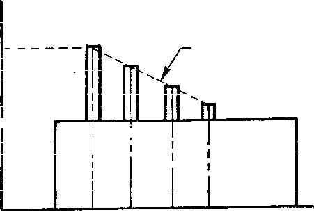 0.01---- 15 Fi F3 FU о 0.03 Frequency (Hz) Turbine engine spectrum 2000 2000 FIGURE 514.4-7. Suggested vibration spectre for-propeller aircraft end equipment on turbine engines bETHOD 514.4 MIb-STD-810E 14 JULY 1989 1-3.4.2.2 Test levels. In the absence of satisfactory mBasurements of field environments, functional test levels approximating jet-noise-indueed and flow-induced vibration my be derived from table 514.4-III and figure 514.4-8. Aerodynamic and jet noise portions are not additive. Use wrst case. 1-3.4.2.3 Testjluration. Test durations should be developed from flight measurement or field data. If field data are not available for developnent of the test durations, then the test levels of table 514.4-III and guidance discussed in 1-4.3, 1-4.6, and 1-4.7 apply. These levels represent maximum actual operating conditions and are functional test levels. The requirementg of 1-3.4.9 also apply. 1-3.4.3 Category 6 - Helicopter aireraft/lnatalled. 1-3.4.3.1 Background information. Helicopter vibration is characterized by broadband random with superimposed strong vibration peaks, as depicted in figure 514.4-9. These peaks are generated by the rotating components in the helicopter, such ais the nain and tail rotors, engines and gear meshing. Ths operating speeds of these conponents under flight conditions are nearly constant, varying by only about five percent. The relative levels of these peaks differ throughout the helicopter, depending on the proximity of the sources, geometry of the aircraft, and location of the test itera. Thus, the need for measured data is especially acute. An obvious requirement for helicopter equipment design is to avoid a nstch or near match between an items resonant frequencies and the excitation (aource) frequencies at the installed location. The major peaks in the helicopter vibration spectrum are usually associated with the main rotor. However, each type of helicopter will have different sources within different areas of each aircraft. Since the vibration environment is dominated by these source frequency peaks, it is logical to use some of these frequencies for exposure in the laboratory test. Normally about foiff frequencies are chosen for the tests. For equipment mounted on engines, refer to 1-3.4.1. For equipment exposed to gunfire vibration, refer to Method 519. TABLE 514.4-I1I Broadband vibration test valuea for jet aircraft equipment. Criteria Aerodynamically induced vibration (figure 514.4-8) I/ Functional test level 3/, 4./ % = Kiq) Jet engine noise induced vibration (figure 514.4-8) 1/ Functional test level 2/, 3/. 4/. 5/, 6/ = CO.48 cos- G/К) [D Vi/k)-+Df(Vf/А)-1 DEFINITIOtK К = 1.18 X 10 for cockpit panel equipment and equipment attached to structure in conpartments adjacent to external surfaces that are smooth, free from discontinuities. (K = 2.7 x 10 if q is in Ib/ft) К = 6,11 X lo~ll for equipment at-t-ached to structis e in coirpartments adjacent to or iirmediately aft of external surfaces having discontinuities (cavities, chines, blade antennas, speed brakes, etc.) and equipments in wings, pylons, stabilizers, and fuselage aft of trailing-edge wing root. (K = 14 X 10 if q is in lb/ft~) q 57.46 N/.1* (1200 Ib/ft) or maximum aircraft q. *sichever is less. = engine core exhaust diameter, meters (feet). (For engines without fans, use maximian exhaust diameter.) Df = engine fan exhaust diameter, meters (feet). R = minimum distance between center of engine aft exhaust plane and the center of gravity of installed equipment, meters (feet). Ш engine core exhaust velocity, meters per sec (feet per sec). (For engines without fans, use maximum exhaust velocity without afterburner.) Yf = engine fan exhaiist velocity, meters per second (feet per sec). 0 = angle between R line and engine exharjst axis, aft-vectored, degrees. A = 1850 if engine exhaust velocities are in feet/sec. A = 564 if ertgine exhaust velocities are in meters/sec. . 10(0.6 = Kg/60}. = 10 (0.6 - 0.0075 lb) Values of are restricted to the range 0.25 to 1.0. 4/ For 70°< 0<180°. use в = 70° to conpute W. 5/ For engines with afterburner, use w. which is four times larger th3.n cotrputed using maxinsjn V, and Vj Without aiterbifl>ner. 6/ For instrument panel equipment, reduce the 0.04 G/Hz value of figure 514.4-8 by 3 dB andreduce the calculated value by 6 dB for functional testing. Endurance is 0.04 g2/Hz. TABLE ?14.4-III. Broadband vibration test values for jet.aircraft equipment. - Continued NOTES 1 / Worst саяе aerodynamic or jet engine induced vibration should be identified and enveloped. 2/ If aircraft has more than one *r.gine. shall be the sum of the individually conputed values for each engine, 3/ To account for the effect of equipment inertia on vibration levels. may be multiplied by a nags loading factor M based on equipment veeight in kilograms (Pounds). This does not apply to equipment v*iich is on isolators. сок 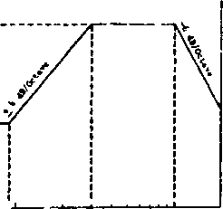 Ушт ЭОС ТгшЩ?№г,су Иг) 1000 Figure 514.4-8. Suggested vibration levels for high per f orroance aircraf t. FK)TES: a. For povger plant induced vibration: = 0.05 X Mj g VHz; (If Wj < 0.04 g/Hz, use 0.04 g/Hz) . b. For aerodynajTiic induced vibration: W- = K(q)2/Hz: (If W, <0.04g2/Hz. use 0.04g2/H2). for values of q and K, see Table 514.4-1II. c. Duration: The test duration Should be based on the in-service duration of expoSiire. The amplitudes quoted are the naxinum anticipated mission levels. The test duration may be reduced by collapsing (normalizing) the in-service levels to these levels. d. The test levels shovm should be considered as equipment excitations. e. Aerodyriamic and power plant indjced excitation should not be considered additive; for testing рш*ро8е8, neorst case conditions should be identified and used. f. Kg = test item weight. 1 ... 19 20 21 22 23 24 25 ... 43 |
|
© 2026 AutoElektrix.ru
Частичное копирование материалов разрешено при условии активной ссылки |