 |
 |
 |
| Главная Журналы Популярное Audi - почему их так назвали? Как появилась марка Bmw? Откуда появился Lexus? Достижения и устремления Mercedes-Benz Первые модели Chevrolet Электромобиль Nissan Leaf |
Главная » Журналы » Preparation instrucnons requirements 1 ... 20 21 22 23 24 25 26 ... 43 ю к 0.02
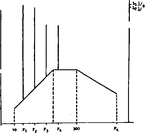 rrequene/ (S&} NOTE 1/ Li, L, and G-Levels are determined frcm TABLE 514.4 - IV FIGURE 5U.4-9. Suggested vibration spectrua for equipment mounted on hellcoptera. 1-3.4.3.2 Teat levels. For the reason stated above, the test levels for equipment installed in helicopters should be derived from field measurement, wftien measured data are not available, the test levels can be selected from figure 514.4-9 amd table 514.4-IV. These levels are an attenpt at enveloping potential worst-case environmsnt-s. They do not represent environments xjnder 4*iich vibration sensitive equipment should be expected to perform to specification. Costs for many devices are a strong function of the performance required in a particular vibration environment. Consequently, performance vibration levels should be tailored to particular applications and are not appropriate for a ffieneral standard. For testing purposes, the aircraft сш1 be divided into three zones, shown in figure 514.4-10. All equipment locations included in a vertical projection of the main rotor disc should use the source frequencies of the nain rotor in determining the values of Lj, Lg, Lg. and L4 (see table 514.4-IV). For equipment that will be located in the horizontal projection of the tail rotor disc, use the source frequencies of the tail rotor in determining the values of Lj, L2. L-j, and L. The fundamental main and tail rotor source frequencies. Fj, for many helicopters are given in table 514.4-V. All equipment located on drive train conponents such as gear boxes and drive shafts should use the source frequencies of that drive train conponent (i.e.. gear mesh frequencies, shaft rotational speeds). These drive train source frequencies must be determined from the drive train areas for the helicopter of interest. 1-3.4.3.3 Test dviratiQn. Test dLPations shall be derived from the field measurements and actual flight characteristics and durations. 1-3.4.4 Category 7A - Assenbled external stores. Jet aircraft. Assembled jet aircraft stores will encounter three distinct vibration environments: captive flight, buffet nanexjver. and free flight. 1-3.4.4.1 Captive flight. Extensive measin?ement programs have shown that the vibration experienced by an external ly carried store on a jet aircraft arises from three distinct sources: a. Aerodynamic boundary layer turbulence. b. Buffet maneuvers. o. Aircraft-induced vibration. In general, store vibration is primarily cajsed by brosuiband aerodynamic boimdary layer turbulence and is relatively independent of the carrying aircraft and mounting location on the aircraft. Instead, vibratory excitation is mostly influenced by store shape, mounting configuration and dynamic pressxire. This source of vibration is distributed along the entire surface of the store and is difficult to simulate by point input of vibration, such as from a vibration shaker, unless the store is relatively stiff. Thsrsfops, an acoustic test (Method 515) is recoiimsnded for this environmsnt. с- Г 00 о Drive Train Source Frequencies Predominate 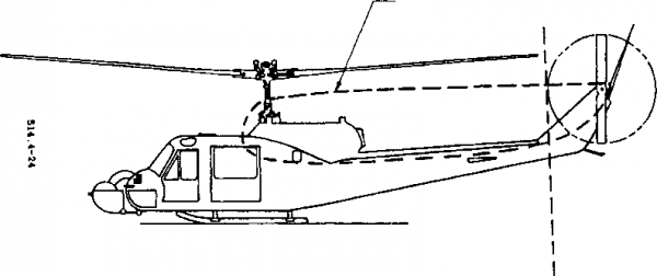 Miiin Rotor !3ource Frequencies Predominate Tail Rotor Source Frequenclee Predominate FIGURE 511.A-10- ZlBMfiJUlCJCQbJiaLltinajilCBtaCt.. шь-зто-аюЕ 14 JULY 1989 TABLE 514.4-IV. Suggested fxinctional teat peak levels for equipment installed on helicopters. Peak Vibration Level Equipment Location Source Frequency (Fx) Ranges (Lx) at Fx-Gs
(2): NOTES: (1) Fx = Source Frequency of Interest = Fj. F2, F3, or F Fi = Fvmdamental Source Freqincy F- = 2Fi F, = 3Fi F4 = 4Fi 1фоп determining values of Fj, Fj, F3. or F. (figure 314.4-9) select the appropriate source frequency range for each vshen determining peak vibration levels. The sovrce frequency ranges are not presented in order of F,=F-. (2) Ft, Fq, F:, F4 must be determined from drive train areas for the particular helicopter . 1ЙТЕ (1) is then applicable. KErraOD 514.4 ROTARY WING AIRCRAFT MAIN ROTOR Fj (HZ) У TAIL ROTOR Fj (HZ) 2/ 0H-58A 0H-58D UH-eo CM-47D CH-47C AH-1 UH-1 AH-64 OH-e СЯ-54 500KC> LYNX 11.8 28.3 17 11.3 12.3 10.8 10.8 19.3 31.9 18.5 41 21.7  1/ These frequencies are presented as the nviitoer of rotor blades times the rotor rotational speed. 2/ Rotor rotational speed. 3/ CH 47 has two main rotors and no tail rotor. TABLE 514.4-V. Fdamental aouree frequenciea (F). MIL-STD-eiOE lA JULY 1989 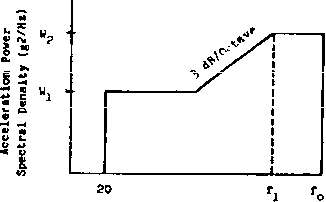 SOTE: Use table 51i*.4-VI to define tf and Frequency (Hr) FiaUHE 514.4-11. Беяропае threahoid ppectrtm for aaaeiiibied external gtore garried on Jet alreraft in ths absence of flight Haasurements. КЕТЮО 514.4 The lower-frequency portion of the asseniDled store vibration spectr-UBn eomes from either aireraft-induced vibration or buffet папеиуегя. Aircraft-Induced vibration generally is present during the entire captive flight phase for a store. Its frequency range is covered by the response threshold spectrum shovm in figxjre 514.4-11. 1-3.4.4.2 Buffet maneuver. Becent flight test programs on the F-16 and F-15 with various externally carried stores have shown intense vibrations associated with buffet na-neuvers. Other similar aircraft, such as F-14. F-18, or next generatian fighters, have the potential to produce intense vibrations during high-performance naneuvers. The buffet naneuver envelope is generally bounded by speeds of 0.8 to 0.9 Mach and altitudes of 3 to 10 kilometers (9,840 to 32,800 ft). Although the vibration levels during high-performance mameuvers are very intense, they generally do not last for more tham 10 seconds, reaching their peak in less than a second and rapidly deteriorating in 5 to 10 seconds. For the purpose of establishing test durations, a commonly used assunption is that an aircraft store may experience as much as 30 seconds of maneuver buffet vibration for each hoxjr of captive-cauriage flight. Buffet maneuver vibration energy is concentrated in the low frequency range, typically between 20 to IQO Hz, dominated by the stores structural chsiracteristics. Depending \xpon the store location on the aircraft and configwation on the rack, pylon, and aircraft, additional distinct responses may be predominant in the store response due to compliance of the pylon interface. Due to these factors, vibration levels should be derived from in-flight vibration measurement. The maneuver buffet and aer-odynamic vibration tests may be combined or performed separately if necessary to duplicate both rigid body and bending modes. 1-3.4.4.3 Free flight. For stores that are deployed by separation from the aircraft (free flight) such as bombs and missiles, a free-flight functional test is reconnended Men the free-flight vibration anplitude is greater than the captive-flight levels. In general, if the free-flight dynamic pressure is greater than the captlve-f 1 lt levels it can be assisned that the associated vibration level will also be higher. In this case, if measured free-flight data da not exist, the factors Aj and A2 from table 514.4-VI should be set equal to one. The value of q should be the mucinun value attainable during free flight. The duration of this functional test, per axis, should eqml the maxinun free-flight time expected at maxinium vibration levels. 1-3.4.4.4 Test levels. The test levels and specta for the three vibration environments, captive flight, free flight, and buffet, can be selected from table 514.4-VI and figures 514.4-11, 12, and 13- The use of these tables and figias Is suggested only when there is an absence of satisfactory flight measurements. Due to normal mounting orientation of external stores and the corresponding low vibration levels in the longitudinal axis, the store excitation shall be applied only in the vertical and lateral axes. 2.00 - 1.00 H CM 0 с Ю .10 -  f.= First Body Bending Mode Frequency of Store 1000 2000 Frequency (Hz) Test tiase - 10 ainutss based upon folloHing assunptions: Average maneuver - 6 seconds Total captive flight life of 150 hours, with a total of 100 buffet maneuvers in the lifetime. riaUKE 514.4-12. Maneuver vibration, response jpectrun. 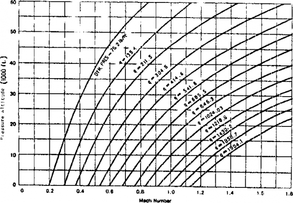 ПОУПЕ bU.t- 1 a.thflMmlbglMMaiOlLaAAJlunaikMlolAlaeh Numhf /tf fiH/fftfrt. TABLE 514.4-VI. Vibration,criteria for,external stores., carried on airplanes. Paramstric Equations for Figures 514.4-11 and 514.4-14
Location, Ccnfiguraticn, Special Adjustnsnts single stores Stores carried side Ь side stores carried behind other Stores Factor Aft half of air fired missiles Aft half of all other stores Forward half of all stores Bl 1 B2 4 Blunt noSed stores, II/ Single and side by side Behind other stores All other stores C, 2* 1 1 Free fall nunltions with non-Integral finned sheet metal tail cones Air fired missiles All other stores 8 1 4 FireboMbs (jelly filled) All other stores -1 Ч 1/2 1/4 1 1 1 ... 20 21 22 23 24 25 26 ... 43 |
|
© 2026 AutoElektrix.ru
Частичное копирование материалов разрешено при условии активной ссылки |