 |
 |
 |
| Главная Журналы Популярное Audi - почему их так назвали? Как появилась марка Bmw? Откуда появился Lexus? Достижения и устремления Mercedes-Benz Первые модели Chevrolet Электромобиль Nissan Leaf |
Главная » Журналы » Preparation instrucnons requirements 1 ... 21 22 23 24 25 26 27 ... 43
DEFINITIONS q = maximum captive flight dyneunic pressjre in Kg/n? (lbs/ft ). (See Note 1) и = average store weight density in Kg/n/- (lbs/ft*) (total wight / total volume t = local store average skin thickness where R is msasured - meter (inches) R = one-half the average of the najor and minor diameters - meter (inches) for a store with an eliptical cross-section (for cylindrical sections use local geometry; for conical sections use smallest Ij calculated using geometry within one foot of equipment mounting point: for oast irregular shaped cross-section, R shall be one-half the longest inscribed chord; for inonocoque irregular crcss-ssction. fj = 300 Hz) NOTES ; 1. For endurance test, q = ьаьв Kgs/m- (1200 lb/ft- ) or maxiniuni q, vmiehever is less. 2. Free fall stores with tail fins, jse fj = 125 Hz: f2 = CxCt/RJxlO ♦ 1000 Hz. 3. For generalruse fuzes which oan be used in several stores; use Wj = 0.04g /Hz: 2 = 0.15 g/Hz: fj = 100 Hz: fg = 1000 Hz. 4. Acceptance range for parauneter values: 40 lP(.i50 wereP is in Ib/ft- 0.001<.t/R<0.02 vshere t&P. are in inches. or if calculated values fall outside these limits, use these limit values. 5. For circular and elliptical cross-sections. f = 500 Hz for all other cross-sections. TABLE 514.4-VI (Continued) Representative parameter values to be used for captive flight Wnien specific tAhLE 5i4.4-VI iContinijed) 6. С - I where t&K are in inches С = 2.54 X 10 were t&R are in meters 7. If fl200 Hz is calculated, use 2000 Hz. S. И 5 X 10 if q is in lbs/ft 9. N Maximum number of anticipjated service missions for store or equipment. (N>3) 10. T = Test time per axis, hours (ТИ) 11. Blunt nosed refers to configurations with separated aerodynamic flow at or Just aft of the store nose. Optical flats, corners, sharp edges, bluffs, and op>en cavities are potential sources of separation. Any nose other than smooth, rounded and gently tapered is suspect. The engineers responsible fer store aerodynamics design and perfornance should make this ueterminaticn. 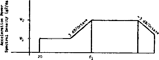 Frequency (Ht) FIGRIRE 514.4-14 Suggested vibration test levels for equipment installed in external stores carried on jet aircraft. 1-3.4.4.5 Test duration. The test duration should be developed from flight mBasvmements, flight characteristics, and flight dwations. If these data are not available, then test duratior.g can be obtained from the information given in 1-4.3, 1-4.6 and 1-4.7. 1-3.4.5 Category 7B - Equipment, installed in externally carried stores. 1-3.4.5.1 Background, information. Equipment installed within an externally carried store mil experlenee a broad-band vibration spectгШп that depends chiefly on the captive-carry regpor.ge of the store. Vibration t@stir.g, v*er.ever possible, should be based on in-flight measiA>ements. If satisfactory flight пваяш*егавп*я are not available, functional tests may be derived from figure 514.4-14 and table 514.4-VI. Note that the test levels for equipment installed in stores are the Same as the response test levels of assembled stores. The response of the store is the input vibration to an item installed in the store. If buffet-maneuver and free-flight conditions can occur- for the store into woiich the equitent will be installed, vibration test spectra need to be developed for each condition. 1-3.4.5.2 Test levels. If sufficient measured data do not exist, use figtire 514.4-14 and refer to 1-3.4.4. Vibration testing of equipment to be Installed in externally carried Jet aircraft stores should be input-control led testing (see I- 4.2.6). 1-3=4.5.3 Test dm-ation. Refer to 1-4.3, 1-4.6, and 1-4.7 for test dis>ation and endurance test criteria. 1-3.4.6 Category 7C - Assembled external stores, helicopters. 1-3,4.9.1 Баскягоипа„-iniormaiion Conplex periodic waveforms characterize the service vibration enviroranent encountered by assembled stores externally carried on helicopters. Lb.llke stores carried on fixed-wing aircraft, externally moimted helicopter stoics receive little aerodynamic excitation, particularly d)en conpared with the rotor-induced vibration. Thus, most of the vibratory energy reaches the equipment through the attachment points between the aircraft and the store. Some excitation, however, is added along the entire store structure due to periodic rotor-induced ргезаш е i iuctuations. The result is a еощр1ех response, miqije to the particular aircraft-store configuration. Therefore, realistic testing depends almost totally upon the use of in-flight vibration теазш етепЛв. This environment is Simulated by exposing the test item to a low-level broadband random spectrum with discrete vibration peaks at the frequencies and first three fundamentals of the aircraft main rotor (source dwell testing - see 1-4.2.2). 1-3.4.6.2 Test level. As stated above, because of the strong dependency of the vibration level on the aircraft-store cont!ir.ation, the use of msasured data taken on the store itself is recomnended for setting the levels. The resulting teat spectrum shall include exposure based upon the source dwell concepts of 1-4.2.2. The suggested vibration conditions from table 514.4-IV and figure 514.4-9 can be lised for initial testing prior to acquisition of field data. NErraOD 514.4 1-3.4.6.3 Test duration. The test dxiration shall be developed from flight test data. Exposure periods shall be developed by constructing a life cycle based on the measured flight environment, equipment life requirements and aircraft mission profiles. If flight test data are not available, test durations can be selected from infornation provided in 1-4.2.7, 1-4.3, 1-4.6 and 1-4.7. 1-3.4.7 Categorv 8 - Ground mobile. 1-3.4.7.1 Background information. The ground mobile environment consists largely of broadband random vibration resulting from the interaction of vehicle suspension and struetiB es with road and surface discontinuities. The natjre of the terrain, vehicle speed, vehicle dynamic eharaeteristics, and auspenslon loading all affect vibration responses. In general, the vibration spectrum of wheeled vehicles and trailers is predominantly random, with peaks and notches, considerably higher and lower than the mean level, at various discrete frequency bands. There is presently no analytical model of this environment suitable for generalized test application. This environment can be simulated by a wide-bsmd random vibration test similar to the minimum integrity spectrum for aircraft as given in 1-3.4.9. The use of a smooth spectrum similar to figure 514.4-16 generally will produce an overtest at some parts of the frequency spectrum. The spectra of 1-3.3.1 and figure 514.4-4 are typical of Mcieeled vehicles and trailers axxl again could produce unrealistic test conditions for installed equipment, Шеп these mjrves are used, consideration must be given to the structures response at the location uiiere the equipment is installed, as it relates to the major structural meni>ers Sijpporting the cargo bed. The track-laying vehicle environment (figure 514.4-5) is characterized by the strong influence of the traek-iaying pattern. The mDvemBnt of the vehiole, its suspension system, and road discontinuities produce a broadband random excitation vshich is further extended or excited at frequencies associated with the track i>attern. This environment is best simulated by superiirposing narroi>and random over a broadband random base. 1-3.4.7.2 Test levels. As dlscxjssed above, generalized test levels for vsiiseled vehicles and twro-viee 1 ed tracks have not been develoi>ed which would be applicable to a specific case. The information, levels and curves presented in 1-3.3.1 and 1-3.4.9 must be adapted for a specific test item. Whenever possible and justified by the program requirements, the actiial vibration environments should be measured before testing the equipment and the results used to formulate a more accijrate sp>ectrvim shape and level. Nijneroue test levels have been developed for tracked vehicles. The spectra given in table 514.4-AIV represent the enviroruBent for aarainition in the \№gmarin hull pack for the MlAl main battle tank. This rack was found to produce the sssst severe vibration environment of any of the racks in that tank. Similarly, table 514.4-AV is the spectrum for the hull rack of the Ml tank wtiich produces the most severe vibration environment of any of the 105-nin racks in the Ml or M60 series of tanks. Tables 514.4-AVI through AXI are the spectra for amnunition and various other itena of installed equipeasnt at various locations in the M1C9 sel f-pr-opel lad howl tsar. Similarly, tables 514.4-AXII through 514.4-AXV present the spectra for items of installed equipment at various locations on the MllO self-propelled howitzer. Vibration spectra for varioi4S locations on the Ml 13 armored personnel carrier are given in tables 514.4-AXVI through 514.4-AXX. For installed equipraent in the turret and hull areas of the M60A3 tank, the vibration test levels are presented in tables 514.4-AXXI and 514.4-AXXII respectively. 1-3.4.7.3 Test duration. The test duration oust be related to the test items service scenario. Appropriate test durations are given in 1-3.3.1 and 1-3.3.2; the test durations for the various tracked vehicle spectra are presented on the respective tables. 1-3,4.8 Category 9 ~ Shipboard vibration. 1-3.4.8.1 Background information. Equipment installed in ships will receive vibration stresses resulting from natural environmental inputs to the ships superstructure, and local unit transmissibilities (amplifications) within the equipment ajid its mounting stPUCtlSe. Vibration testing of shipboard equipraent should address both the levels cf environmental inputs and the susceptibility of equipment/mounting resonances to input frequencies. Shipboard vibration spectra have a random conponent induced by the variability of cruising speeds, sea states, maneuvers, etc., and a periodic conponent inposed by propeller shaft rotation and hull resonance. Equipment mounted on masts (such as antennais) can be expected to receive higher input than equipment mounted on the hull or deck. 1-3.4.8.2 Test level. Whenever possible, measvn>ements should be used to develop the test criteria. In the absence of Shipboard measurements, levels foisx! in figure 514.4-15 should be used. The random vibration test of shipboard equipment should follow either the Basic Transportation Test (1=3.3.1) or the Bench Handling Shock Test (Method 516.4, Procedure VI). .001 PSD g2/Hz Frequeney (Hz) FIGURE 514.4-15. Threshold performance random vibration soectrw for equipment Installed in ships (non-combat). In order to verify structural integrity and the conpatibi1ity or equipment/ mounting resonamce frequencies wth shipboard input frequencies, a sinusoidal vibration test should t>e conducted in accordance with MIL-STD-167 for Type 1 (Environment Vibration). In the event that actvial shipboard vibration data recorded on candidate vessels show levels or frequency ranges different from those for MIL-STD-ie?. Type I. ths test levels should be tailored to envelope the highest values for each frequency, with appropriate consideration given to the fatigue life of the equipment. 1-3.4.8.3 Test duration. The test durations for shipboard applications should be based t4>on the anticipated deployment scenarios. For tests wnich utilize the test levels from figise 514.4-15. the test duration should be two hours along each of three orthogonal axes. 1-3.4.9 Category 10 - Miniimm Integrity teat. 1-3.4.9.1 Baekground inforaation. Vibration levels of figise Э14.4-16 ssd 514.4=17 and durations of table 514.4-VII are not based on application environaents. Rather, exjjerience has show! that equlpoent *iich withstands these exposures ftstctions satisfactorily in general field use and that equipment tested to lowar levels does not. These exposure are sometimes called Junk tests artd provide reasonable assurance that equipment can withstand operations and handling during field installation, removal and repair. These exposures ere based on typical electronic boxes. Wien bexms or asselles are too large, unnecessarily high loads are induced in mounting and chassis structures while higher frequency vibrations experienced by electronic devices are too low. In these cases the mininun integrity test should be applied to subassentolies. Maxinun weight of an item or subassembly should be approximately 36 kilograms (80 pounds). Minimum integrity tests should be applied as a basic test for itmas which are not designed for any of the other vibration environnents of table 514.4-1. Note that a secured-cargo test from 1-3.3.1 is probably also needed since all material is siibject to transportation environments. Minimum integrity tests should be applied as a sijpplemental test for: a. Items tested on vibration isolation devices (1-4.8). b. Items tested hardmounted to levels and durations less stringent than the applicable mininun integrity test. 1-3.4.9.2 Test level. The test levels shosei in figures 514.4-16 for general use and in figure Figure 514.17 for helicopter equljasent. 1-3.4.9.3 Test duration. The suggested test durations are provided in table 514.4-VlI. TABLE 514.4-VII. MinimLim integrity test durations
с 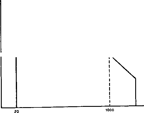 O.OHl--- 6 db/OCT 2000 Frequency (Hs) FIGRJRE 514.4-16 Minimm integrity test-general. о a о и с о 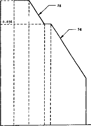 14 33 52 Frequency (Hi) I FIGURE 514.4-17. Minlmun! Integrity test-hellcoptars. 514.4-40 1-4 SPECIAL CONSIDERATIOMS 1-4.1 Conbined temperature, vibration test. To expose materiel to realistic service stresses, a conobined tenperature-vibration test may be necessary. The high and low tenperatures that materiel is expected to endure while being transported are usually specified in the requirements docunents in terms of the climatic categories described in MIL-STD-210 or AR 70-38. These same criteria are presented for ijse in Methods 501.3 (High Tenperature) and 502.3 (Lew Tenperature). The tenperature values selected for those tests can be xjsed for confined tenperature-vibration testing. 1-4.2 Test techniques 1-4.2.1 Random vibration. The majority of vibration experienced ay eqiupment in operational service has been determined by analysis tc be br-cadbarid in spectral content. That Is, all frequencies are present at all times In various conblnatlons of Intensity. Controlled experiments have demonstrated that random vibration effectively simulates broadband in a test situation. Therefore, most of the tests in this method use random vibration. Random vibration spectra are defined in terms of aueleratlon spectral density (also referred to as power spectral density, or PSD) profiles, vtiidh relate energy density levels to specific frequency bands. The vibration is defined over a relevant frequency range. The use of g-rms values alone to describe vibration tests is not valid, since a g-rms valvie does net chaoacterise a specific viteation profile. An infinite ccsi;inaticn cf frequency bandwidths end spectral shapes ossi satisfy one g-rms value. Therefore, vibration measurements and test spectra should always relate energy content to specific frequency bands. As traditionally applied In the test laboratory, random vibration is characterized by a gaussian energy distribution, but other forms of broadbwd excitation (mechanical or electro-hydraulic) may be enployed if the desired spectral control cam be achieved. 1-4.2.2 Source dviella. In some cases, the vibration environment is characterized by periodic excitation from reciprocating or rotating structures and mechanisms (e.g., rotor blades, propellers, pistons, gunfire). This excitation may be transmitted through fluids (air or liquid) or structures. When this form of excitation predominates In a critical frequency band, source dwell vibration is impropriate. A source dwell excitation is characterized by broadband random, narrowband random, or one or more sine waves. This teczviique differs from the traditional sinvBcidal г спвпс-в diNell test. A rescr.ance dwell endiasizes those frequencies at !Ф.1сЬ the test item resonates. A source dwell enphasizes those frequencies which predominate In the platform environment. Obviously the source dwell spectrum provides a more 1 ... 21 22 23 24 25 26 27 ... 43 |
|||||||||||||||||||||||||||||||||||||||||||||||||||||||||||||||||||||||||||||||||||
|
© 2026 AutoElektrix.ru
Частичное копирование материалов разрешено при условии активной ссылки |