 |
 |
 |
| Главная Журналы Популярное Audi - почему их так назвали? Как появилась марка Bmw? Откуда появился Lexus? Достижения и устремления Mercedes-Benz Первые модели Chevrolet Электромобиль Nissan Leaf |
Главная » Журналы » Preparation instrucnons requirements 1 ... 23 24 25 26 27 28 29 ... 43 47. Hardy. V. S. Surface Ship Vibration (A Sunmarv of Vibration on Surface ships Prior to 1966). Washington: Naval Ship Research amd Development Center, 1967. Docunent No. NSEADS H 2338. 48. Alma, H= F. and N. W. НхшИ. Surface Ship Vibration (A Бшяпагу of Vibration Data on Sxirface Ships Collected between 1 Jantarv 1966 and 31 March 1970). Vteishington: Naval Ship Research атк1 Development Center, 1970. Docjment No. NSRADC R 2338. Supplement A. 49. Steinberg, D. S. Vibration .alvsis for Electronic Equipssnt. New York: Vftley, 1973. 50. Hagen, A. Vibration Test Besults on Mast and Hull of 1Ж-1053 Class Ocean Escort Vessels. Washington: Naval Ship Research and Development Center РШ-380. 1974. Docvnent No. SAD-31E-1962. 51. Kallas, D. H. Review of M.ilitarv Sta.n.dard mtL-STD-167 (Ships! Revision A Applied to Surface Vessels. Februeuy 1965. Lab Project 9300-15. Tech Memo No. 2. DTIC No. AD-463-939. 52. Chalmers, R. H. Environmental Conditions for Shipooard nard% are. Joijnal of ..EnvironmBntal Sciences, 24:5 (Septenfeer/CctubeF) , pp. 13-22. 53. Guidelines toJxtilitarv Standard MIL-STD-167-1 (Ships). Mechanical Vibrations of Shipboard Equipment. March 1965. Docunent No. NAVSEA 0900-LP-090-3010. 54. Fackler, W. C. Inter-action Equivalences. IN: Equivalence Techniaviss for Vibration Testing. Shock and Vibration Monograph SVM-9, Oiapter 5. Wteishington: Shock and Vibration Information Center, 1972. 55. International Test Operating Procedure (ITOP) 1-1-505. Vibration Testing. 4 Mar 1987. DTIC AD No A17842i. 56. Connon. Willia-T. K. (Ill), Methodology Investigation. Final Jieport. Ground Vehicle-loose Cargo Vibration Schedules. January 1987. DTIC AD No B114ei9L. dB = 10 loglOS where W. = measured acceleration power spectral density in g/Hz vnlts Wq = specified level in g/Hz imlts. Confirmation of these tolerances shall be made by the use of an analysis system providing at least 100 statistical degrees of freedom. Fcr all prccedvs>@s using broadbf random vibration wiUi random peaks, sinuBoidal peaks, or soiirce dwell, analysis systems shall be less than or equal to 10 Hz in bandwidth up to and including the frequency of the highest peak in the test spectrxsn. II-l.1.2 Ana lysis/control systems. Digital analysis systems are preferred for vibration control and analysis, because they have аес-ш ае1ев in excess cf staridard analog 3r.alysis and control systems. Digital systems should have the following capabilities: SECTIQH II II-l APPARATUS. Any vibration-Inducing machinery capable of satisfying the test conditions is acceptable. II-l.l Data-analvsia/vibration control systems 11=1.1.1 Tolerances. Tks acceleration poneer spectral density of the test control signal shall not deviate from the specified requirements by more than 3dB over the entire test frequency range. However, deviations of -6dB in the test control signal may be granted for frequencies greater than 500 Hz dije to fixture resonance, test item resonance, or facility limitations. The cumulative bandwidth over wnich this reduction shall be allowed cannot be greater than 5X of the test frequency range (see figure 514.4-18). In no case shall the acceleration power spectral density be more tham -6 dB below the specified requirements. No deviation shall be granted for freqtiencies below 500 Hz. Wien the test cannot be controlled within ±3 dB from the specified requirement, at the risk of the tester, the test may continiie. The risk shall be to assume no overtesting is occurring, test results are valid, and appropriate corrective action will be taken in ac-ccrdance with the r.ature of the test. Tolerance levels in terms of dB srm defined as: с a, t 500 ATj Frequency (Bz) Reference 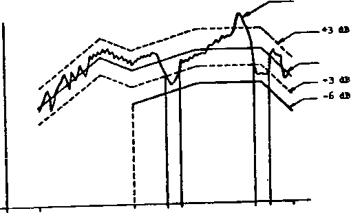 luFi sSi ef Test W FI9URE 514.4- 18. gvapy* f acceptable performance within tolerence. ll~l--2.1 On-line contiguous filter systems. On-line contiguous filter, equalization/analysis systems must have the following characteristics: В 25 Hz, maxisun betveen 20 and 200 Hz В 50 Hz, naxinun between 200 and 1,000 Hz В > 100 Hz, maxinun between 1.000 and 2.000 Hz or (pf,) (Hz/second) maxinun, 4)ichever is 6 smaller. II-l.2 Test pet VP II-l.2.1 Procedure 1 II-l.2.1.1 Category - gfigjc transportation. Mount the test item on the vibration equipment using restraints and tie downs typical of those used in actual transport. I I-l. 1.2.2 SWBPt frequency aVafcemg. 3 ept frequency analysis systens nust have the followrine characteristics: a. Constant bandwidth (1) Filter bandwidth as follove: Б s 2§ ХИ, iBaXioiss between 20 and 200 Kz В = SO Hz, maxinLBn between 200 and 1,000 Hz В 100 Hz, maxinun between 1,000 and 2,ООО Hz (2) Analyser averaging time => T 2 ВС 1 second, maxinun, shsre T s Trje averaging time and RC = analyzer time constant. (3) Analysis sweep rate (linear) = R = В or B (Hz/second) maxinun, imiehever is smaller. 8 b. CongtSf), percentage landwjth analyzer (1) Filter bandwidth = pf, *= one-tenth of center frequency maxinun (O.lf,), 4\ere p = percentage arid fj, * analyzer center frequency, (2) Analyzer averaging time в т = SO. mininun (3) Analysis sweep rate (logarithmic) = H - 11-1.2.2 Category 4 - Propeller Aircraft тпе test item shall be installed in a vibration fixtcpe veiieh simulates the actual application configLSfation. To the extent practical, the vibration test setup should incorporate actual .scunting and installation provisions from the carrying aircraft. Fixture designs which utilize the maximum amount of platform structure possible will allow the best item to respond to the laboratory excitation in a manner more closely duplicating its response in the actual field environment. II-l.2.1.3 Category 5 - Jet aircraft and tactical missiles. (See II-l.2.1) II-l.2.1.4 Category 6 - Helicopter/aircraft/installed. The test item shal 1 be attached to the vibration exciter by means of a fixture capable of transmitting the vibration conditions specified. The fixture shall be designed by utilizing actual racks, panels or platform structures of the helicopter to minimize the introduction of unrepresentative response within the test item. II-l.2.1.5 Category 7Д - Assembled external stores. Jet aircraft 11-1.2.1.5.1 Fixtures. Svispend the store from a strix:tural stpport by means of its normal ncunting lugs, hooks and sway braces simulating th© operational nsountlng configuration. Include launcher or mounting rails where applicable. Rigid body store suspension modes shall be between 5 and 20 Hz except that the highest rigid body mode shall be no higher than one half the lowest test frequency. In some instances in the past stores have been hard mounted to large shakers. This has proven to be inadequate and should not be attenpted. Vibration shall be transmitted to the store by meams of a rod or other suitable mounting devices running from vibration shakers to the surface of the store. The tie points on the store surface shall be relatively hard and structurally supported by the store internal structure or supported by an external fixture (usually a ring around the local store diameter) attached to the store. sejDarate driving points will be required to drive the verical and lateral axes. Separate driving points at each end in each axis are also recomnended although aligning a single driving point in each axis with the store aerodynamic center has also been successful. II-l.2.1.5.2 Acce1erometers. Accelerometers to monitor the vibratory response of the store should be mounted on two relatively hard points or rings within the store, one in the nose section and one in the aft section. For stores such as bombs with nonintegral tail cones, the aft-ssction mounting point should be in the aftmost section of the main body of the store. At each mounting point or ring, two accelerometers should be movinted--one in the vertical and one in the lateral plan. (Longitudinal direction is along the axis of the store; the vertical direction is defined as perpendicular to the longitudinal axis and contained in a plane passing through the mounting lugs). 11-1.2.1.6 Category /и - Equipment installed, in external ly. carried stores. (See II.1.2.1) II-l.2.1.7 Category 7C-seirbledexternal stores, helicopters. Testing shall be acconplished in three mutually perpendicular axes with the mounting lugs in the up position. The test item should be attached to the fixture by its normal mounting means (e.g., suspension lugs for 2.75 inch FFAR laimcher). The vibration fixture shall utilize, if feasible, actual aircraft conponents for acconplIshing this test attachment. 11-1.2.1.8 Category 8 - (3round ncbile. The test item shall be attached to the vibration generator directly or with a fixture, and securely held by its normal means of attachment. Tbe fixture shall incorporate actual service structures as much as possible to minimize unrealistic response characteristics during test exposure. Any connection to the test item, such as cables, pipes, vidres, and the like, shall be arranged so that it inpcsss restraints and nass similar to those present siier. the equipment is installed in the operational configuration. Excitation shall be applied through the three orthogonal axes of the test item. II-l.2.1.9 Category 9 - Shipboard. Equipment should be mounted in its normal configuration with normal shock/vibration isolator mounts used throughout the test. II-l.2.1.10 Category 10 - Mininaro integrity. The secured cargo transportation test phase shall be acconplished as indicated in 1-3,3.1. The additional vibration exposure shall be acconplished with the test item secured to the fixture/exciter. Items which are mounted on vibration isolators should be tested with the isolation removed. The items shal 1 be tested in each of three orthogonal axes. II-l.2.2 FreceduFq II - Categorv 2 = Large ia5eu bly transport. The test set xsp uses the actual transport vehicle a,nd test track to sinsilate service conditio.ns. Secure the test item on the traxisport vehicle for normal transportation. II-l.2.3 Procedure III - Category,3 -Loose cargo transport II-l.2.3.1 Package-test. The test sett ijses a package tester as depicted in figure 514.4-IS. The fixturir required is as shown a-id will not secure ths item to the bed of the package test-er. A vertical ispact wall and sideboards as depicted i.n Г1 ш>е 514.4-19 shall be installed to contain the test items on the bed of the package tester. The fence opposite the vertical inpact wall is not intended as an inpact surface, but is used to restrain the test item from leaving the tester. The distance to this restraining fence should be sufficient to prevent constant inpact, but still prevent one or more of multiple test items from walking away from the others. The height cf ths test enclosure (sideboards, inpact vsal 1 and restraining fores) should be at least 5 cm higher than the height of the test Item to prevent ijireallstic inpacting of the test item on the top of the enclosure. KETIK)D 51 Ы m m M 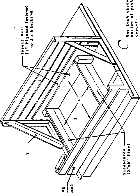 и -a-in в о i-i e :
HETTOD 514.4 II-l.2.3.2 Test bed. The test bed of the package tester shall be covered with a panel of 1/2-inch plywood, with the finished side \jp and the grain parallel to the drive chain, (marine plyviDod Is гееопЕПеПаёи ЪёсайШе it Is generally iiiore durable.) The plywood shall be secured with bolts or six реглу nails, with tops of heads slightly below the sijrfaee. The bolts or nails shall be spaced at sufficient intervals around al 1 four edges and through the center area to prevent oilcanning of the plywood. II-2 FpgTlOl..fOR TPST 11-2.1 General preparation Step 1. Perform life cycle analysis described in section 4 of this standard Step 2. Identify test categories which are applicable and pertinent from the life cycle analysis. Step 3. Determine test conditiors for each applicable and pertinent category. Step 4. Select appropriate test apparatijs, data collection and analysis equipment. Step 5. Prepare the test item in accordance wiith General Bequirements, paragraph 4 and as specified for the test category. step 6. Exaaslne the test item for physical defects, eto. and йосштпЬ the results. Step 7. Conduct an operational check and docunant the results. Step 8. Proceed to the required test procedure if no problems are found; otherwise, correct the problems and restwt wath Step 6 above. 11-2,2 гоотФжт III - Loose eartfo transport. Using suitable wooden sideboards, the test item shall be constrained to a horizontal motion of 5 cm (free space) in a direction parallel to the axes of the shafts, a distance more than sufficient to insure the test item will not rebound from sideboard to sideboard (i.e., the distance between sideboards shall be equal to the width of the test item plus 5 cm. Initial positioning of the test item wrLll be such that there are 2.5 cm cf space cn either Side. If sere than one siailar Itea is tested siBSJltaneously, 2.5 cm of additional free space per additional item should be used between side boards, the initial spacing should have 2.5 cm betvnen test items and 2.5 cm to the sideboards; the total free space should not exceed the length of the longest horizontal axis of the test item (to prevent test item rotation). Multiple similar test items shall not be separated by sideboards unless specified in the requirements documents. II-3 FHOCEDURES 11-3.1 Procedure I II-3.1.1 General ocedurs Step 1. Coirplete steps 1 thro\jgh 8. II-2.1. Step 2. Inspect the test item to establish pretest criteria and physical condition. Step 3. Verify the test items functionality. Step 4. Mount the test item on the vibration equipment as required by the applicable paragraph of II-l.2.1. Step 5. Expose the test item to the test level and duration as determined from 1-3.3 or 1-3.4 and II-3.1.2. The test item shall be operated as if it vwere in op>erational usage. (see 1-4.10, 1-4.11 and 1-4.12) Step 6. Inspect the test item and conpare it to pre-test data and physical condition. Verify the test item functionality and record the results, (see 1-4.11) Step 7. Repeat steps 2 through б (see 1-4,6) for each axis (see 1-4 = 2 = 5) arad each test. Step 8 Document the test results in accordance with I1-4. II-3.1.2 Special considerations II-3.1.2.1 Category 7A Assembled external stores,Jet aircraft Step 1. Apply broadband vibration to the store using an input spectrxsn shape of the store-mounted forward accelerometer response spectrum from 1-3.4.4. The input level should be 6 dB down from the calculated response level of the forward accelerometer. Step 2. Identify those frequencies at v*iich the store-mounted accelerometers, in the direction of applied vibration, exceed the applied input vibration by 6 dB or greater. There may be different frequencies for the forward and aft accelerometers. Step o. Peak or notch the applied input spectrvBn until both the forward-eind aft-mounted accelerometers in the direction of applied vibration at their respective frequencies identified above equal or eKceed the required test levels determined from 1-3.4.4. It may be necessary to move the points of attachment between shaker and store until locations are found where both ends of the store are simultaneously excited to their respective test levels. SOTE: The off-axis accslsronster resporss (those accelsromstsrs 90 degress to ths applied vibration) should be examined. For each frequency where the response of a off-axis accelerometer is above In-axis response levels, the following actions are suggested. For each of these frequencies, calculate the ratio of required to observed levels for each accelerometer which was in the direction of vibration (in-axis) and those perpendicular (off-axis) accelerometers which have excessive level: Average these ratios for each frequency. Ths input vibration spectrum may then b© adjijsted so that at each of these frequencies, their respective average value is equal to unity. II-3.2 Procedure II - Large assembly .transport. Step 1. Conplete steps 1 through 5, II-2.1. Step 2. Inspect test item to establish pretest criteria and physical condition. Step 3. Verify the test items functionality. Step 4. Place the shelter cn the transport y6hicls(s) that is ncrnsilly ijsed to transpюrt vehicle. Step 5. The shelter shall be sec\n:*ed in its normal manner to the transport vehicle. Step e. Install instrumsntation in ths shelter to msasure the vertical axis acceleration history on the shelter floor. Step 7. Drive the trailer/shelter combination on the Munson Test Course at Aberdeen Proving (Sround, Aberdeen, Maryland or an equivalent course. Step S. The trailer.sheIter oontination shall be driven five times over the followdng sections of the course at specified speeds: NOTE: The speeds will be utilized as specified unless the speed poses an unsafe driving condition, in which case the maximum safe operating speed will be utilized. 1 ... 23 24 25 26 27 28 29 ... 43 |
|
© 2026 AutoElektrix.ru
Частичное копирование материалов разрешено при условии активной ссылки |