 |
 |
 |
| Главная Журналы Популярное Audi - почему их так назвали? Как появилась марка Bmw? Откуда появился Lexus? Достижения и устремления Mercedes-Benz Первые модели Chevrolet Электромобиль Nissan Leaf |
Главная » Журналы » Preparation instrucnons requirements 1 ... 24 25 26 27 28 29 30 ... 43 (a) Coarse wBishboard (6-Inch waves spaced 72 inches apart) -5 MPH (b) Belgian block - 20 Н (c) Badial washboard (2-inch to 4-inch waves) - 15 №H (d) 2-inch washboard - 10 HRl (e) Э-inch spaced bump -20 КРЯ Step 9. Inspect the she Iter/test item and conpare to pre-test criteria and physical condition, (see 1-4.11, 1-4.12) Step 1С. Verify the test iteraa fmetionality. (see 1-4.11, 1-4.12) Step 11. Pocunient the test in accordance with II-4. II-3.3 Procedure III - Loose cargo transport. II-3.3.1 Gteneral information a. Configmstion. The test item(s) is placed on the plywood-covered bed of the package tester in its packaged configuration or as otherwise prepared for loose-cargo field transportation. The test item shall not be operated during this test \jnless specified in the requirements documents. b. Orientation. The orientation of the test item should represent its issst likely shipping orientation, and the longest horizontal axis should be parallel to the throw axis of the package tester. For palletized items, the pallet skids should be pairallel to the throw axis of the package tester. If the shipping orientation is unknown, the test item should be tested with its longest axis parallel to the throw axis of the package tester. Any changes to the orientation of the test Item due to the movement of the package tester (except as noted in (3)) shall not be corrected. c. (Cautions. Since proper rotation of the table should cause the test item to rebound against the impact wall, any item not doing so should be rotated 180 in the horizontal plane in an atteopt to change any movement caused by test item weight distribution. N6 test will be started on an area of plywood on viiich the top ply is danaged or нот through. II-3.3.2 Detailed procedure Step 1. Conplete steps 1 through 5, II-2.1. Step 2. Inspect test item to establish pre-test criteria and ixiyslcal condition. ШТЮО 514.4 Step 3. Verify the test items functionality. Step 4. Prepare the package tester/test ©quipment in accordanee with provisions of II-2.1. Step 5. Place the test item which has been prepared for field transportation on the bed of the package tester/test equipment. Step 6. The package tester/test equipment shall be operated to provide the test level and duration as specified for category 3. 1-3.3.3. Step 7. Inspect the test item and conpare to pre-test criteria and physical condition. If applicable, verify the test items functionality. (see 1-4.11. 1-4.12) Step 8. Document the test in accordance with II-4. II-4 INFORMftTIOM TO BE RECORDED a. Test item identification (manufacturer, serial number, etc.). b. Prior test history of the specified test item. c. Inspection and test procedure, including inspection requirements, test criteria, instrumentation, data requirements, and failure criteria. d. List of all test equipment, including vibration generating and analysis eqviipment, mounting arrangements, id fixtures, e. Orientation of test item, including axes of applied vibration. f. Location of accelerometers used to control and measiire vibration. g. Resonant freqxiencles, including those selected for tsst, as applicable. h. Isolation characteristics, including sway anplitudes and transmissibi 1 ity versus frequency. i. Applied test levels, durations, and frequency ranges. j. Besults cf all perfcrnsnce nssasjrensents. including cver-all test results, k. Analysis of each failure aund corrective action proposed. 1. Analysis bandvfidth. KETKOD 514.4 APPENDIX A (UND VEHICLE BESPONSE VIBRATION DATA itopendix A provides measured vibration data from military vehicles as indicated on the individual tables. Table 514.4-Al represents the cargo environment at the floor of a composite of two-wheeled trailers, the l/4-ton, M416 and the l-i/2 ton. M105A2. The data include differing Vehicle load conditionB traversing over specially designed courses ranging from paved highway to offroad conditions at various vehicle speeds. As seen, in figxa-e 514.4-IV the sctectrum is characterized by broadband random with peaks and notches at various discrete frequency bands. The break points of the peaks and notches are given for establishing the spectrtim shape. TwD-wheeled trailers of significantly different size and design may provide substantially different input to the cargo loaded on the bed than given in table 514.4-AI and spectra should be adjusted accordingly. Table 514.4-AII represents the cargo environment at the cargo bed of a conposite of tactical wheeled vehicles, the 5-ton Мв13 and MB14 trucks, M36 2-1/2 ton truck, CUCV M1009 1-1/4 ton truck, and the 12-ton M127 semi-trailer. The data include differing vehicle loading conditions traversing over specially designed courses ranging from paved highway to oiiroad conditions at various vehicle speeds. Again the spectrun is broadband random with peaks and notches at varioijs discrete frequency bands. Break points are provided for establishing the spectrim shape. Tactical wheeled vehicles of significantly different size and design provide substantially different input to the cargo loaded on the bed than given in table 514.4-AII and spectra should be adjusted accordingly. Table 5i4.4-AIII represents the enviroranent at the floor of the M548 tracked vehicle. The data utilized for establishing these spectra veers derivsd from measuremgnts of the vehicle operating at various speeds over special ly design eo\n ses ranging from paved highway to offroad conditions. This environment contains a low level of broadbamd random ijpon vhich is superimposed narro A)and random discrete frequency bands. The broadband random base is from the basic movement of the vehicle, suspension system and road discontinuities. The narrowband random excitation is associated with the track-laying pattern and road sm*face. Tables 514.4-AIV through 514=4-A3QtII represent the environments of several coiribat vehicles (MlAl tank. Ml tank, M109 self propelled howitzer, MHO self propelled howitzer, M113 armored personnel carrier and M60A3 tank). In Tables 514.4-AIII through 514.4-AJDHl, the term test phase is defined as the vibration environment at one or more vehicle speeds. The test phases are used to insupe that there is no overlap of vehicle speeds within a given phase. TABLE 514.4-AI. RaLndom vibration program data for smcxsed сгз'Ш.о transportation, conposite two-unhealed .trailer. Test duration per axis: 96 minutes per 32 miles Vertical Axis Transverse Axis Longitudinal Jxis
КЕТЮО 514.4 RNB = 1.27 514.4-Аеб
heraoD 514.4 5-SOO Ht Tcsil Thfcshold EbAlB и£ШхХ TABLE 514.4-AiiL QMdaijuuidua=mi=cmdmLyituaLmjuux [Ql[JUШ£l£aIxa.IшшQПiUia[LJшJLxlibi£l£ AmpI Sweep BW artowband 3 Ajnpl Sweep BW Ampl Swticp Swcc]{> Sweep BW BW Ampl BW HW Ampl BW Ш1й im. ij!zjtizi im im oii-im VER-nCAL axis; (12 minutes per test phase) 1- (M 00 о >
fRi\NSVlERSE AXIS (12 minutes per test phaise)
LONGITUDINAL AXIS (12 minuiLes per teist p>has ) 60-70 0.01182 82-94 0.0II5S 106-1X1 0.02Ю6 142-17(1 0.0Ш 188~2M 0.1301 6 6 12 18 18 90-105 0.0074 9 120-140 0.0116 12 150-175 0.0084 15 159-195 213-264 282-336 0.0177 0.0400 0.0512 27 27 212-260 0.0223 24 284-352 0.0284 36 376-448 0.0201 36 2(i5-323 3!tS-440 0.0204 0.0132 30 45 Tb eamageralioD facilor шшш 2.0. > § I S 5 2 § 8 i s e> e e e v Q e о D 2 r. e N N m ift 2 S S S 1 s = s s s s s о d e о S Я s I я S s a 2 я S! e> л deed 21 8 к i3 8 = 51 s г eoee CN I I vt e I I v> ! ii I e e I о о s s s $ = I i s a в Ц a e d e e vt * >e о s : s s <n о r- - 0> ?) SDKS S S S 8 3 e e d e if = 1 i я s ! S 8 О Г4 f>4 s d о d I ? S 1 I I ! i 9! ? S 8 Я S a ж СЧ m Oi S S S 8 e e ё о V> чг о О r<4 С n СЧ V г S X га m <е >п > о - - гм Л г- W> W1 . е е о е d d d < fe I s - о I я I S %l 8 i g 2 OS deed
о METHOD 514.4 § 5-500 H Floof TiMl Ltvtl TABLE 5i4.4-A,v. Ш11а^а1;1ш1лшйш=Шк=аш1ш^аЬШ19а12а1Ш1т^ aшalшШailLUaшш[UijlJ[LMUiшk-iшlLIa£k Test duration per axis: 115 minute!! p<!r SOCIO rnileis Ho. tm Smmm ШЛ Ampl SwMp BW Ш1Х fclinmrbind 3 Ampl Swcicp BW Ш XItU) Ampl (torn VEIimC/iL AXIS (415 minuteis ркт test phase) vO 00 < vO О И NmmwlMinl 4 BW BW Ampl NiLiTowband il Swiwp BW BW Sweep Ampll BW > о
TRANS/ERSE AXI!> {AS minuteii p<er test phase)
LONGITUDliNAL AXIS (IS minutes per test phase)
99-123 1311-1(18 \u)-m 237-2!>l 0.0036 0.0131 0.04)2 0.0862
TIm exa(g*nlioB (tctoir was 2.0. 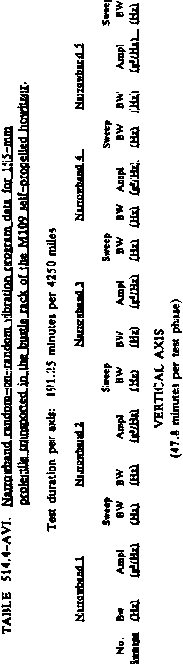 i s I f s i A 6 r- e N V 5 ж S * * s: Й S I S Я I e Й e © © fM e S T * T <o Ф СЧ <e M M M CO h 11 S Й Я S2 -5 ! 7 r 3 I о о 84 N 9 s e о I T 7 S <B ~ <e Ш e л In - ra - СЛ n ft f 2 £ о л r*- g 5 1 Л X 2 S £i S S Й s г s - n m 1й
mm s s s s г s d d d d 3 S T T M л к s S i w 2 m in d d d d M N S 7 T T 7 <b lb ё r in ю m ra ra J, e J a s I к 5 S 8 e e e с d с - N If OOOO > > > > ? ? S 8 8 5 d d e = Я Я S P P P P - Г- rj 8i§i I §§§§ I METHOD 514.4 51Л,Л-А71 1 ... 24 25 26 27 28 29 30 ... 43 |
|||||||||||||||||||||||||||||||||||||||||||||||||||||||||||||||||||||||||||||||||||||||||||||||||||||||||||||||||||||||||||||||||||||||||||||||||||||||||||||||||||||||||||||||||||||||||||||||||||||||||||||||||||||||||||||||||||||||||||||||||||||||||||||||||||||||||||||||||||||||||||||||||||||||||||||||||||||||||||||||||||||||||||||||||||||||||||||||||||||||||||||||||||||||||||||||||||||||||||||||||||||||||||||||||||||||||||||||||||||||||||||||||||||||||||||||||||||||||||||||||||||||||||||||||||||||||||||||||||||||||||||||||||||||||||||||||||||||||||||||||||||||||||||||||||||||||||||||||||||||||||||||||||||||||||||||||||||||||||||||||||||||||||||||||||||||||||||||||||||||||||||||||||||||||||||||||||||||||||||||||||||||||||||||||||||||||||||||||||||||||||||||||||||||||||||||||||||||||||||||||||||||||
|
© 2026 AutoElektrix.ru
Частичное копирование материалов разрешено при условии активной ссылки |