 |
 |
 |
| Главная Журналы Популярное Audi - почему их так назвали? Как появилась марка Bmw? Откуда появился Lexus? Достижения и устремления Mercedes-Benz Первые модели Chevrolet Электромобиль Nissan Leaf |
Главная » Журналы » Preparation instrucnons requirements 1 ... 27 28 29 30 31 32 33 ... 43 1-3.1.3 Froceuxsre III - Mission profile. A raission profile test can be used viien a close correlation is desired bstvssen test tine and acovstic stress exposis-e tims in serviee. This is not an accelerated test since testing is performed at real istic stress levels. 1-3.1.4 Procedure IV - Cavitv resonance test. Aircraft compartments or stores that open during flight can expose cavities to the airstream. Standing waves often become established in such cavities at the rescr>ant frequencies cf the cavity. The resulting acoustic noise is very intense. 1-3.2 Choice of test conditions. The choice of test conditions depends on a. The procedure chosen. b. The availability of msasured data on the test items operational acotetic environment. c. The location of the test item with respect to the noise source. d. whether the noise зош'се in the operational environment is localized or distributed. e. The mission prof lie(s). f. The predicted life-cycle history of the item. 1-3.2.1 Spectrvm .shape. The spectrum shape shall be determined from measured data. If available (see Т-4Л). If data uf e not available, use the spectrum given in figure 515.4-1, with two exceptions: For assenbled. externally carried aircraft stores, use the spectrum given in figure 515.4-2. For cavity resonance testing, use the spectrun given in figure 515.4-4. 1-3.2.2 Acoustic test level. The acoustic tsst level should be determined from measured dat, if available (see 1-4.1). Otherwise, use the values suggested by table 515-4.1 a. Procedures I, II, and IV - The most severe acoustic stress conditions shall be used as test conditions. b. ProceduBf III The measwements shall be taen for the entire mission, including periods of low stress. For this procedure, the test level is varied over time, but the test does not exactly duplicate a mission in this respect. Test levels should be determined using three techniques described in 1-3.2.3.1. > a. S i о = w> g О uj 0£ -9 H - 3 dB Octave -3 dB Octave Upper Limit Lower Limit -to dВ Octave !0 dB Ocuve -1-1- 250 1 250 1/3 Octa\e Band Center Frequenc> (Hz) 8000 FIGURE 515.4 1. Siiygftwted 1/ octave band aoectra for eoustleal nelse test. КЕТЮО 515.4 MIL-?TD-B10E 14 J.-LY 1989 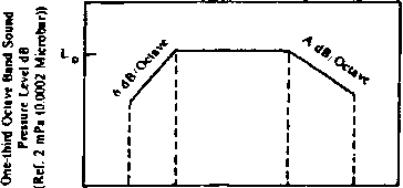 100 300 f о 2000 Frwjuency (H?) Note: See table 515-3-11 for definition and calculations. fo = 600 log (X/F) ♦ С Д = б dB/oetave w&en Tq > !iOQ Kz h = 2 dB/octave when fn i 00 Hz FIGURE 515,4-г. Qnfi-third ggtavc band spectrum for acouatlc teating of aaaeabled externally carried aircraft aiorea. 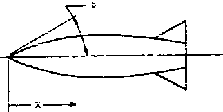 FIGURE 515.4-3. TvPea atore profile 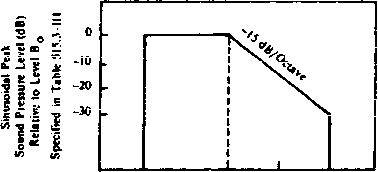 FIGURE 515.4- !. 10 300 1000 2 COO Cavity reaonance Acouatic teyt leVela 1-3.2.3 Test duration. Fop procedure III, test duration should be determined as described in 1-3.2.3.1. For all other procedures, determine the test duration by referring to table 515.4.1. 1-3.2.3.1. Dynamic .pressure histogram. For airborne equipment, the test mission profile should be based on the dynamic pressure histogram. Test cycle duration should eqxjal the average duration of the missicns used to develop ths histogram. The percentage of time spent at each dynamic pressure band level in the test cycle should be in proportion to the relative contribution ot the same level to the histogram. The test cycle, therefore, resembles a service mission with varying test levels as a function of time. The test cycle is then repeated until the desired number of missions has been аюсШШхаЪеа. Each mission profile should be expressed in a dynamic press\A>e versus time profile rather than Mach number amd altitude profiles. The dynamic pressure profile for each mission is analyzed to develop a histogram of mission time spent at various ranges of dynamic pressure. This is acconplished as follows: Using the highest measured value cf dynamic prssurs (rGgardlsss of missicn) ~~ g sum al 1 of the mission time for which dynamic pressures were within five percent of ijiQ- Then, sum all of the mission time for wiiich dynamic pressures were between 0.95 g and 0.90 gnjx- Continue this process of suiming mission time for five percent increments of dynamic pressure until all values of measured dynamic pressure are included. For test рш*ройея. the ргеяяш*е levels can be determined using the midpoint-dynamic pressure value of the appropriate five percent dynamic pressure band. This value will be assumed to be constant for the amount of flight time iwithin this band. Т-ТПЛ ГТ .-....Ь 4... 1 я....... tm... ..1............ w.. , . Л. J X. ... ж 1 л. A. ж X . .-х 1 w u\j xi-aj iwctt. iiie i u .l doiie 3ui ij4s auj UB ueu мгчгх xts* uxiif {/ширине их the test a.nd the available acoustic noise source. For enviroranental wsorthiness tests the 1д>рег limit on figure 515.4-1 can be ignored and the tolerances on figure 515.4-2 can be -3 dB to plus infinity. For qualiflcation testing the tolerances should be as shown on figure 515.4-1 and for figure 515.4-2 they can be -3 dB for each one-third octave band. 1-3.2.5 AcoTgtic source. The fluctuating pressure environasnt sxperisncsd in service is a conplex combination of progressive wave and reverberant acoustic fields. Because of practical limitations, equipment testing is generally acconplished in ]:*everberant laboratory facilities. If am appropriate laboratory facility is not available, a jet engine may be able to provide the required acoListic field. 1-3.2.5.1 Reverberant testing. This technique ia used hen the pressure fluctuation source is distributed. Such a source is turbulent boundary layer flow along a vehicles skin. Reverberant testing is also used for equipment located in closed spaces inside a vehicle exposed to strong localized acoustic sources.
1/ In the qualification teat, the pureesure levels and ex;poeure times for categorleii A thru Gl are for the fiLjnctional test. No sepairate endurance test is i>eqiiired. 2/ Reference 20 цРа (2x10 * dynea/cm?). 3/ Already adjuste<l for a reverberant test envlronmtmt, ее 1-3.2.5.1. 4/ U:se only 10 miniijtes of exposure for environmental wiorthiness test. If ffaggeste<l dijration is less than 10 nninutes, use shorter durationi. I- 00 (Ж о 1-3.2.5.2 ProgreBBive wave testinn. ТЫв technique 1в used to sinulate a strong localized acotetlc source. The acoustic energy sweeps over the test item like ripples spiading on water. This test environment is propriate for externally-carried conponents on all types of vehicles vnich are directly exposed to localized acoustic sources such as rocket or jet engines. A reverbemuit test enviroraaent can be <ned to approxiiaate a progressive eve environnent but the level should be adjusted to account for the difference in vibration efficiency of the two types of fields. 1-3.2.5.3 Cavitv resonance testing. It is reconnended tbat sinusoidal acouBtic епвт>ву be used in the cavity resonance tvSt. 1-4 SPECIAL о(Ш1швкР1ат 1-4.1 Acceptable measured,jiata. Measured operational or flight test data can be in either of two forms: (1) atcoufftic pressure levels, or (2> vibration response of the test item in the field environment. For either form of toe data, the data shall be analyzed ш1пв a constant percentage baridwidth no greater than one-third octave ith minimLR of 50 statistical degrees of freedom. The data shal 1 be over a frequency range of at least 20 to 2,000 - and preferably to 10,000 - Hertz. 1-4.1.1 Acoustic operational or flight test data. The levels and spectra measured in flight cannot be xjeed directly aa tbe test conditionB for tbm flight conditions under tNhich they wex measured. Tbey nust be adjusted (recognizing that Mromamia noise is less efflclKit than reverberant acouitle noise at frequencies before the first structural resonance and more efficient x>ve that frequency) to conpensate for the differences between flight twbulent boundary layer pressu fluctuations and a reverberant acoustic test envlronnant. The parametric relationships specified in tables S1S.4-II and S1S.4-III can be used tc extFapclats tc ctheF operational cr flight conditions. 1-4.1.2 Vibration operational or flight test data. Vibration can be used indirectly to establish acoListic test levels. Ths test item is InstwiiBntated with accelerometers mounted identically as those used in operational or flight testing, e acoustic test Levels and spectra are varied until the reproduced vibration matches the p >eviously meastsed operational or f ligbt test data within SfSithcd 514.4 tclsrsnces for random vibration, nils acoustic test environmsnt an ha considered as the operational or flight environment. The parametric relationships specified in tables 51S.4-II and 515.4-III can be used to extrapolate to other conditions. 1-4.2 Test interruption. In the event of an unprogrampsd test interrvption, the caxise of the ifiterrHption should be analyzed to determine the likelihood that environmental stress conditions present at the interriptlon could occur in serviee. Ibe teat ahould be resieed at the point of Interrtptlon tjelng the same specific test item. If the test item has been damaged, it may be necessary to start the test over using a new test item. TABLE 515.4-II Functional test bpi/. 5/, 6/. 7/ = 20 Log (qj) + 11 Log (X) + 7 Log (1-cos ) + O+HdB f 2/. 3/, = 600 Log (X/R) + С Endurance test boi. 1/. §/. I/. = 20 Log (q2/qi) + 2.5 Log (N/3T) + functional level dB
lower) (lbs/ft-*) local radius of store in inches -200 locations within one D of either aft end of store or aftward of re-entrant angle; 400 all other locations naximum store diameter in inches local nose cone angle at X eqxials 1 / Tan = (R/X) (Figure 515.4-3) 72 unless measured data shows otherwise 96 unless measured data shows otherwise 84 -uTilesB measioed data shows othermse 0 for 0.85 < M > 0.95; -3 dB for all other values of M Mach nunfeer Representative parametric values to be used for captive flight vixen specific parameters are not available:
Suggested acoijstic, test levels for assembled externally-carried aircraft-stores. NOTES 1. Raise computed L level by 3 dB for a store carried in a ТШ cluster rack; by 6 dB for a UEJR cluster rack. 2. If calculated f is above 2,000 Hz use гфрег frequency limit of 2,000 Hz. If calculated f is below 200 Hz use 200 Hz. 3. Bound off fjj ip epds to a one-third octave band center frequency. 4. For stores which do not have circular cross-sections the radiijs used in the formulas shall be the radius of the circle iwhich circunscribes the cross-section of the store. 5. For locations on flat nose stores (80° < S<.S0®) iier X < IOC: Ftmctional test Lq = 20 Log (qj) - б Log (x) * E * H Enduranoe test Lq = 20 Log (qj) - e Log (X) + E * 2,5 Log < /3T) * H 6. For long cylindrical section, > 2D, use for locations aore than one D aftward into the cylindrical section: Functional test L = 20 Log (q,) + F + H Enduranoe test Lq = 20 Log (qj) ♦ f ♦ 2.5 Log (ы/ЗТ) ♦ H 7. For changing redlts section either aft ef a long cylindrical section or ti>en X > 100 on a flat nose store, redefine X so that X = 1 at beginning of this section: Fimctional test L - 20 Log (qi) t ii Log (X) ♦ F * H EndLrance test Lq = 20 Log (qg) + 11 Log (X) + F + 2.5 Log (M/3T) ♦ И f = 0.13(M-0.25) (2.4-11/2) Hz 0.57(L)(C) + (2.4-lP72)l2 Definitions fj} resonance frequency for the N mode (wiiere N = 1,2,3,4, etc.) N * mode пглЬег i С > speed of soxjnd at altitude of flight (m/s) ! L = length, radiiM, of opening exposed to airstream (meters) M >: Msch пглЬег a second set of resonance frequencies attall be identified by using the distance pvamitep, L, as the depth of the cavity. ? ! q >: flight dynamic pressure when cavity is open (lbs/ft) ! H * nunber of operational hours store is flown with cavity open. If HO, ! endurance test is not required. I T s duration of test in hours (minlBSJsa T 1 hour) TABLE S1S.4-III Sugtfeated eavitv гевопапсе acoxistic teat., ! Parametric Eqfuations for figure 515.4-4 : Functional Teat Level : Bq 20 Log (q) * 110 dB (Bef 20M Pa (0.0002 mlcrobar)) ! Endurance Teat Level ! Bo * 20 log(q) + 2.5 Log (H/T) ♦ 110 dB (Bef 20УРа (0.0002 mlcrobar)) S 1 ... 27 28 29 30 31 32 33 ... 43 |
|||||||||||||||||||||||||||||||||||||||||||||||||||||||||||||||||||||||||||||||||||||||||||||||||||||||||||||||||||||||||||||||||||||||||||||||||||||||
|
© 2026 AutoElektrix.ru
Частичное копирование материалов разрешено при условии активной ссылки |