 |
 |
 |
| Главная Журналы Популярное Audi - почему их так назвали? Как появилась марка Bmw? Откуда появился Lexus? Достижения и устремления Mercedes-Benz Первые модели Chevrolet Электромобиль Nissan Leaf |
Главная » Журналы » Preparation instrucnons requirements 1 ... 28 29 30 31 32 33 34 ... 43 1-5 R a. Dreher, J.F., E.D. Lakin, E.A. Tolle, Vibroacoustic Environment and Jest Criteria for Aircraft Stores During Captive Flight. Shock and Vibration Bulletin 39, S\pplement irii 1969), pp 15-40. b. ureher, J.F., Effectg.of Vibration andJlcoustie Noise on AireraftVStrее Conpatibility. In: Aircraft Conpatibi 1 ity Synfxjsixmi. Eglin AFB, Fla. Noventoer 1969. Proceedings. Volt 6. pp 245-272. c. Burkhard, A.K. Acoustic Testing to Simulate the Flight Vibration Envirorjasnt of Aircraft Stores. FebrtJBay 1974. AFTDL-TR-TS-llO, DTIC nvS$er AI>=S18-543L. d. Burkhard, A.H., Captive Flight Acoustic Test Criteria for Aircraft Stores. Shock and Vibration Bulletin 43 Part 3 (January 1973), pp 113-126. e. Meeker, B.D. and W.D. Everett, LS Navy Ejcperience on the Eifeets of Carrier-Aircraft Environment on <3uided Missiles. 19.pa 80 NATO AC3AHD Conference Proceedings No. СГГГО. f. Heller, H., G. Holmes, and E. Covert, Flow Induced-Pressure Oscillations in Shal low Cavities. Decentoer 1970. AFFDL-TR-70-104. DTIC nunber AD-880-496. g. Smithi D= i id L. Shaw, Prediction of Pressure Oscillations in Cavities Exposed to JVerodynamic Flow. October 1975. AFFDL-TR-75-34. DTIC number AD-A018-518. 1-4.3 Retest recTuirementa. When failupee occur dviring qualification, the failure will be fixed as appropriate. The test will be restarted and rtjn through the conplete qualification cycle to verify the fix. Parts 4ilch survive a conplex qxjaliiication cycle are considered to have passed and are repaired only il required to finish the retest. 1-4.4 Overtest. An Interrwtion in the test that results in a more extreme exposure of the test item than required by the equipnent specification should be followed by a conplete physical iruspection of the test item and an operational check prior to continuation of the test. An engineering Judgment shall be made nhether to continus testing with the specific item given the overtest to obtain a new item, or to cor,sider ths test conpleted. 1-4.5 Failure analysis. Al 1 incidents where the test item does not meet the equipment operating requirements shall be analyzed to determine the cause and inpact of such occurrences. Corrective actions shall be proposed or inplemented as required to meet equipment performEtnce requirements. METHOD 515.4 ACOUSTIC NOISE STCTION II II-l APPJgATUS. Acoustic noise tests can be performed using a reverberant test chanber of sufficient power and size. A reverberant test chamber should have a volune at least ten times the test item volume. With the chaniber enpty, the distribution of overall sound pressure levels should be uniform to within -2 and 4 dB of the deeired value. If no test ehassber is available, ths noise field behind a Jet er.gine car. be used for acoustic noise testing, provided desired isiiformity of test enylronnent can be achieved. The spectrum and overall level should be measxired and the test item placed in a suitable location to achieve best approximation to desired test conditions. It is difficult to achieve as uniform an acoustic environment as with a reverberant test chamber. This approach may be suitable primarily for development, test-analyze-fix, and environmental WDrthiness tests. However, because of the difficulty in controlling test conditions, this approach is not always suitable for qualification testing. II-l.l Controls. The acoustic test facility shall be able to produce acoustic noise at the desired levels and frequency range. Frequencies outside the desired frequency range nay be inadvertently produced by the acoiistic test facility but do not need to be controlled. The acoustic envirorjnsnt shall be within the tolerances for the particular test procedure. II-2 PREPARATION FOR TEST. step i. Choose unich test procedxire shall be conducted (1-4.1). Step 2. Determine overall acoustic test levels, durations, and spectra shades to be produced during testing. Step 3. Prepare test item in accordance with Qeneral Requirements, 5.2.2. The item shall be in the operational coniigua*ation. Step 4. Motsit test item. For Procedta-e IV, to to step 7. Stipend the test item by means of springs or cords. If a mounting structure is required between the soft sxjspension and the test item or to hold the soft suspension, care nust be exercised to asstjre that no spurious acoustic or vibratory inputs are introduced. The natural frequency of suspension shall be less than 25 Hz. The test item shall be exposed on every surface to the sound field by centrally locating it in the test chamber. The test vclvsns shall be nc more than 10 percent cf ths tsst chamber vcluns. №.en tha test chamber is rectangular, no major surface of the test item shall be Installed parallel to the chanber wall. Spectrun control. The response of the ndcropbones in each reference plane shall be averaged to give an average noise spectrun for each reference plane. The average noise Spectrum for each reference plane shall be shaped to be snthln - 3 dB and +6 dB xsiless otherwise stated. Step 7. <3o to tbe appropriate test procedure. II-3 PBPCEPORE II-3.1 Procedure I- Environmental worthiness-test Step 1. Mount the test item m the test (dtamber and position the instrunentatlon as given in II-2. Step 2. Expose the test item to the required acoustic levels and spectra for the specified ansj-cmt of tine as in T-3.2.3. The test item Shall rsot bs energised durirg step 2. Step 3. (Леек the test item for loose parts, chafed wires, and any other obvious diameter. Correct or repair before proceeding to Step 4. Step 4. Energize the test item. Chs< the test it fvRcticns for proper operation. Correct or repair any dasage. Step 5. Expose the test item to the required acoiistic noise for the specified amount of time with the test item functioning as if it were in actual operation or flight. Step 6. Check the test item for loose parts, chafed asiree, and any other obvious dassge. Step 7. Repair or correct as necessary before flight testing. METHOD 515.4 Step 5. For testing of assembled externally-carried stores, go to step 6. Position at least three microphones to measure the sound pressure field. These microphones shall be located in proximity to each major dissimilaj* test item surface, at least 45 cm (18 inches) from the test item surface or one-half the distance to the nearest chajnber wall, тхспёУег is lees w,th the charter empty. The average overall so\jnd pressure distribution around the test item shall be measured and be uniform vnthin -2 and +4 dB of the desired value. Step 6 Microphone plakcement. Establidi three reference planes perpendicular to the longitudinal axis of the store at poeitione one-eixth. one-half, and f ivc-sixtha of the length of the store. In each of these reference planes, position three microphones aroiAid the store, 120° apsu°t. Eaui microphone Shall be within 45 era (18 inches) of the store surface, but no ftsther from the store than one-half the distance between the store and the nearest baffle. MIL-STD-810E Step 8. Docixnent the test as in 11-4. II-3.2 Procedure II - QualificationJTest Step 1. m>unt test item as given in II-2. Step 2. Position instrxaentation as specified in II-2. Step 3. Operate the test item as if it were in operational or flight usage vile being exposed to acoustic levels in Step 4. Step 4. Elфose test item to functional test levels as in 1-3.2. Step 5. Expose test item to enduraunce levels as in 1-3.2a. Step 6. Check test item for function in accordance with Qeneral Requirements, 4.0. Step 7. If test item is not a store, go to Step 10. Step 8. If a free flight test is required, expose test item to acoustic levels as specified in 1-3.2.2.a and check in Step 9. Step 9. (erate store through free flight periormance requirements. Step 10. Docisnent the test as in II-4. II-3.3 Procedure III - Mission profile tests Step 1. using the guidance of II-2, mount the test item in the test chanber. Step 2= Position instrxjroBntation as given in II-2. Step 3. Expose the test item to the mission profile developed in 1-3.2.3.1, Step 4. During the mission profile test, perform functional checks on the test item as required by General Requirensnts, 4.0. Step 5. Conduct the mission profile for desired nuirber of missions. Step 6. During Step 5 testing, operate the test item as given in Qeneral Requirements. Step 7. Document the test as in II-4. lnnL-STD-BlOE 14 ЛГьУ 1SS9 11-3=4 PrQcedyge IV - Cavity геаопапсе test Step 1. Conduct the preteat inspection (reference II-2). Step 2. Suspend the test item in the chamber so that only the cavities to be tested are subjected to direct iiqpingement of acoustic energy. Protect other surfaces of ths item so that soxsiA pressure Isvels ar at Isast 20 dB loessr. Protection devices ehal1 not dam test item vibrations. Step 3. Position a microphone in the cavity to be tested. The micropbone shal 1 face outward so that its face can be seen when looking dotei into the cavity. Step 4. Регхояп resoneuice dm lis t signifioaTit eavlty Fescnances. The response of the s;icrc;.CRs a&vsfitsd in Stsp 3 shall be ± 3dB ef the levels re p2iPe<i by 1-3.2.2a. Resonance dwells can be done individually or sisultaneously. Verify functioning of test item during acoustic exposure. Step 5. Condtict the post-test inspection. Step 6. DoGisiiEnt as given in II-4. II-4 lUFOJaJUaiOK T03ejECOBDED a. Test item Identification (manufactvirer, serial nuaber. etc.). b. Prior history of the test item. Inspection and test procedures including inspection requirements, test criteria, instrumentation, data requirements, and failure criteria. d. List of test equiiMnent including noise generators, measurement and data analysis equipment, mounts, and fixtures. s. Descriptions of ths tsst sstxp and irjstrvsasntation locations including drawings and photographs as appropriate. f. Log of all actions from pretest through post-test inspection. g. Recorded data. h. Analyses of all failures, malfunctions, and test incide.nts. №THDD 516.4 SHOCK Page SECTION I I-l PUBPOSE ....................... 516.4-1 1-2 QlViroNNENTAL EFFECTS................516.4-1 1-3 GUIDELINES FOR DETEHmlNIKG TEST РЮСЕОЦБЕ AND TEST COЮITIONS................516.4-1 1-4 SPECIE. CONSIDERATIONS ............... 516.4-18 1-5 REFERENCES ..................... 516.4-18 SECTION II II-l APPARATUS ......................516.4-19 II-2 PREPARATION FOR TEST.................516.4-21 II-3 PROCEDLRES.....................516.4-21 II-4 INFORMATION TO BE RECORDED..............516.4-2B SECTION I I-i PURPOSE. Shock tests are performed to assure that materiel can withstand the relatively infrgqusnt. nonrepetitive shocks or transient vibrations encovmtered in handling, transportation, and servioe environments. Shock tests are also used to measure an items fragility, so that packaging may be designed to protect it, if necessary, emd to test the strength of devices that attach equipment to platforms that can crash. 1-2 ENVIRONMEWTAL tihKCTS. Mechanical shocks will excite an equipment item to respond at both forced and natural frequencies. This response, among other things, can cause: a. Failures due to increased or decreased friction, or interference between parts. b. Changes in dielectric strength, loss of insulation resistance, variations in magnetic and electrostatic field strength. c. Permanent deformation due to overstress. d. More rapid fatiguing of materials (low cycle fatigue) . 1-3 GUIDELINES FOR DETERMINING. TEST PROCEDURES AND TEST CONDITIONS NOTE: The tailoring process as described in section 4 of this docxjment should be used to determine the appropriate tests and test variables. a. Application. This method is applicable to all materiel which may be subjected to mschanical shock during its life cycle. b. Beatrictiona. None. c. Sequence. There are often advantages to applying shock and vibration tests before climatic tests, provided that this sequence represents realistic service conditions. HoiMever, test experience has shown that climate-sensitive defects often show xjp газге clearly after the sppl ication cf shock and vibration forces. d. Test variations. The tests vary in apparatus, axes of test, and stress levels applied. 1-3.1 ChoiGe of test-procedures. Method 516.4 is divided into nine procedures: a. F4jnctionaI shock (Procedure I) b. Equipment to be packaged (Procedtire II) G. Fragility (Procedure III) d. Transit drop (Procedis 1у) e. Oash hazard (Procedure V) f. Bench handling (Procedure VI) g. Pyrot-ech.nic shock (Procedw* VII) h. Bail inpact (Procedure VIII) i. (tapult launch/arrested landing (Procedure IX) To find out whether a procedure is applicable, see subparagraphs a and b of the discussion of each procedure in this section. Al 1 shock environments anticipated for the test item during its life cycle, both in its logistic and operational nodes, should be considered. The severity of one type of shock nay obviate the need to perform another type of shock test, but the configuration of the test item during these tests nust be considered thoroughly before making this decision. 1-3=2 Choice of related test conditions. Quldance for setting values for test conditions is found in this section in subparagratphs b, c, and d, of the discussion of each procedure. 1-3.3 Procedure I, - Functional shock a. Appl icatior.s. Procedure I is intended to test equipment asses*>lies (including mechanical, electrical, hydraulic, and electronic) in their functional mode. b. Restrietion. This test procedt£re will not be required along any axis for *iiGfc a sufficiently severe randora vibration test procedure is required, provided that equlpaent operational reqiiireffients are connarable. Bandom test severity ig sufficient if its shock response spectrum, based upon a three-sigma Gaussian acceleration response of single degree of freedom (sdof) systems, exceeds the shock test response spectrum evaryvtere in the specified range of natural frequencies. The quality factor. Q, (danping magnification factor or transmissibi 1 ity at resonance) to be eslcyed is ten, Vulch Is eCfUivalent to five pepoexit of Critical VIscDUb авлф1л£. The three-sigaa shock реярог.ге spectr-ja for ths random test is given, ss a firictlen ef natural frequency of the sdof system, by 31 (ТГ /2)a(f)fQ]l2 in units of acceleration, nere u(f) is acceleration spectral density (AsD) at frequent f vrvtmPwnee a). A covarison of the shock response levels foisid in figise 516.4-1 with ASD levels Is found in figure 516.4-2. c. Test conditiona (1) Shock spectrum aixi transient duration. The shock response spectrun and the effective tranaient duration shal 1 oe derived from measurements of the test items functional enviransant, or from dynamically sealed ттттхягетвпЬв of a siffiilu environment if available. (a) Measured data available. The shock response spectrum required for the test will be determined from reduction of the environmental static acceleration spectra. The spectra will be a conposlte of spectra for positive and negative directions, sometimes called maximax spectra. The analyses will De performed for Q av а%, a sequence o* nawura дгеоиепсхез a xnervaxS Oa oCbave or ssnuxxer ьо span at least 5 to 20,000 Hz= tien a sufficient пин±>вг of representative shock spectra are available, an appropriate statistical basis should be enployed to determine the required test spectrum. Nonparanetric statistical techniques az covered in reference e. Parametric statistics can be enployed if the data can be showi to satisfactorily fit an assumed underlying probability distribution. (For exanple, in aL-STD-1540 the test levels are based цроп a гаа1Х1шш pr-edicted environinent defined to be equal to or greater tb.an the 95th percentile valiie at least 50 percent of the time. ien a r.ormsil or lognormal distribution can be Justified, appendix 516.4A provides a nethod tor estimating such a test level.) When insufficient data are available for statistical analysis, an increase over the maxinun of the available spectral data should be used to establish the required test specvrtm. V.C acccunw *o- varxauixxty of the епухгопшбПи and uncertainty in any predictive mathoda esmloyed. The degree of increase is based \jpor. engineering Judgment and should be supported by a rationale for that Judgment. SI V 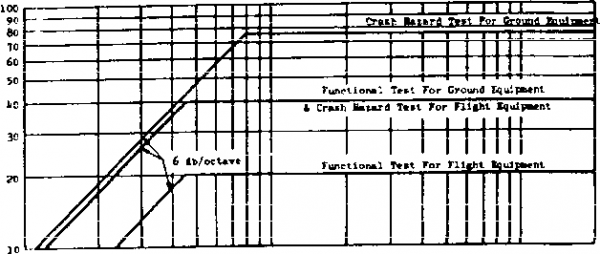 30 1.0 50 60 70 во 100 200 300 boo 500600S00 1000
FIGuhE 516.4-1. Test shoeic reaoonae apeetrta for u m if aeaaured data is not available. MIL=STD-S10£ !4 JULY 1989 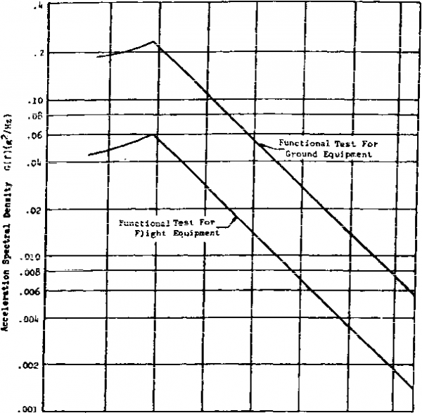 ?5 50 JOG ?00 loo Natural Frequency (Нг) 1600 ?000 Randoni teat insut ssectral density yielding cQulYaJgnl test shpck rcspgRse agestra ahg№ in fjgura 5ife.u l- ---516.4-5 NETHCD 516.4 1 ... 28 29 30 31 32 33 34 ... 43 |
|
© 2026 AutoElektrix.ru
Частичное копирование материалов разрешено при условии активной ссылки |