 |
 |
 |
| Главная Журналы Популярное Audi - почему их так назвали? Как появилась марка Bmw? Откуда появился Lexus? Достижения и устремления Mercedes-Benz Первые модели Chevrolet Электромобиль Nissan Leaf |
Главная » Журналы » Preparation instrucnons requirements 1 ... 29 30 31 32 33 34 35 ... 43 Effective transient durations, Tg. will also be determined from the time histories of the environmental data analyzed. The effective duration is defined to be the minimum length of time *iich contains all data magnitudes exceeding 1/3 of the peak magnitude associated with the shock event. Figure 516.4.3 illustrates this process. The shock input time history used for the response spectrum analysis will be 2Tg in duration starting at a time to include the most significant data prior to and following the effective duration included in the specification of the required test shock. In general, each individual axis of three orthogonal axes can have a different shock test spectrum and average effective dxjration. (b) Measured data not available. If a data base is not available, the applicable spectrum from figure 516.4-1 can be enployed as the test spectrisn for each axis, provided that the effective (above 1/3 of its peak value) duration of the test shock tine history falls between six and nine milliseconds. (Ibis speetrven approximates that of the perfect terminal sawtooth pulse shown in figure 516.4-4.) Any test transient is suitable if it equals or exceeds this sp)ectrum requirement over the frequency range of 5 to 2000 Hz (for exanple. a half-sine pulse applied in both directions of each axis). As stated in 1-3.3b, this shock testing may be omitted if random vibration testing Is required vwith input acceleration spectral density in excess of the applicable spectrun m figure 516.4-2. A less desirable alternative, only permissible if the tester has no shock response spectrun analysis capability, is to enploy a terminal peak sawtooth pulse that meets the toleramces given in figure 516.4-4 with application in both directions along each axis. The presence of superinposed ripple falling within the waveform tolerance band should be minimized to avoid significant overtesting at the frequency of such ripple. (2) Test axes and number of Shocks. The test item undergoing test shall be subjected to a sufficient nunt>er of suitable shocks to meet the specified test conditions at least three times in both directions along each of three orthogonal axes. A suitable test shock for each direction of each axis is one that yields a response spectrum that equals or exceeds the required test spectrum over the specified frequency range vs*ien using a duration of twice the specified Tg value for the test shock time history, and *ien the effective duration of the shock is within twenty percent of the specified Tg value. The spectra are to be determined for positive and negative maximum accelerations (either maxinun absolute or equivalent static), Q = 10, and at least 1/6-octave freqxiency intervals. If the required test spectrum can be satisfied simultaneously in both directions along an axis, three shock rejsetitions will satisfy ths requirement for that sxis. If the requirement can only be satisfied in one direction, it is permissible to change the test setip and inpose three additional shocks to satisfy the spectrum requirement in the other direction: setup change possibilities are to reverse the jxjlarity of the test shock time history or to reverse the test item orientation. JsCL-STI--eiOE U JULY 1989 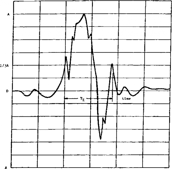 -1/3A Time riGURE 516.4-3- ExaBBle sf a shock tis€ hiatsrv shoeing effective transient duration (Tg). NETTOD 516.4 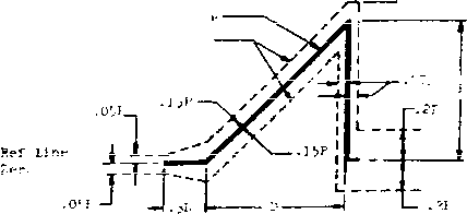
I/ Shock paraaeters a and c: recoasmended for equipraent not shock-motftted and weighing less th 300 pouide, 2./ Equipment mounted only in trucks and semitrailers nay use a 20g peak value. MOTE: The osci i lografn shal 1 include a time about 3D long with a pulse located approxinately in the center. The peak acceleration magnitude of the sawtooth pulse is P and its disation is D. The meastB ed acceleration pulse shall be contained between the broken line boundaries and the measured velocity change ( lch may be obtained by integration of the acceleration pulse) shall be within the limits of V 4.0.IV, vere V. is the velocity change associated with the ideal pulse vtiich equals 0.5 DP. The integration to determine velocity change shall extend from 0.4D before the pulse tc O.ID after the pulse. FIGURE 516.4-4. Terminal-peak sawtooth shock pulse confiduration and Its tolerance limits (for use vihen shock response spectrum analysis capabiUtV-isJot availat)le). It is permissible to simultaneously meet the test requirements along more than one axis with a single test shock. Consequently, it is conceivable that a minimum o£ three test shock repetitions will satisfy the requiremBnts for both directions cf all three orthogor,al axes. At the other extreme, a total of eighteen shocks will be required if each shock only satisfies the test requirements in one direction of one axis. (3) Operation of test item The test item shall be operational before, during, and after test as is appropriate to its functional use. d. Bationale. The intent cf this test is tc disclose failures viiich may result from, or adjistments necessitated by, shocks experienced by aj\ item dwing use in the field. Even though an Item has successfully withstood even more severe shocks during shipping or transit shock tests, there are differences in support and attachment methods and in fimctional checking requirements that make this additional test necessary. Tailoring of the test is required when data are on hand, can be measxired, or can be estimated from related data using accepted scaling techniqtjeB. nhen such data carrot be required, pulse wsivefcrm control, as defined in figure 516.4-4, wsy be tjed, although tegting in both direetipna ia required to assure meeting the Spectrun requirements of figure 516.4-1 in the negative direction. 1-3.4 procedure ?I.- Equipment to be packaged a. Application. Procedure II is to be used wfeen equipBaent will require a shipping container. It establishes a nsiniaasr. critical acoslsration level for a handling drop height. This acceleration level may later be furnished to a package designer as an acceptable critical acceleration. b. Bestrictions. Procedure II is not intended for testing extremely fragile equipment such es missile guidance systems, precision-aligned test equipment, gyros, insrtlal guidance platfor-ins, etc. Wisn the critical acceleration is required, рроогв ill (1-3.5) will be used, c. Test conditions. The unpackaged test item in a nonoperational mode shall be subjected to a series of trapezoidal 30-g shock pulses having a time duration to be determined from table 516.4-X and the equation Tu = 2У<2 h/g) The pulse will be in accordance with figiire 516.4-5. A prograaniable shock machine will more than likely be required to produce these test conditions because of the displacement limitations of shakers. d. Bationale. The trapezoidal waveshape tsls chosen because the ccnputation of velocity change it produces (for cozrpariscn with design drop height) is rruch easier to make and more reproducible than most shock spectrum synthesis routines. Also it provides an upper bound on primary and maximax shock response spectra for given peatk acceleration input levels. KETriOD 516.4 TABLE 516.4-1. Suggested drop height for ртчх;е<1ире III.
for 100 percent reboiind 1-3.5 Procedures-III -..Critical acceleration fragility a. Application. Procedure III ia used to determine an Items fragility level so that packaging can be designed for it, or so the item can be redesigned to suit packaging requirements. b. Bestrictiorts. Procedure III is to be used % hen the critical acceleration for an item nust be determined. c. Test conditions. A design drop height will be selected based on measurement of the test items shipping environment, or from table 516.4-1 iien measured data are unavailable. (A design drop height is the height from which the test item might be dropped in its shipping configuration and be expected to survive.) A maxlmLin test item velocity change may be taken from table 516.4-1 or determined by using the fol lowing relationship: AV = 2 V 2gh where Av = naxinLMn product velocity change cm/s (in/s) (sTnmation of inpact velocity and reboind velocity) h - design drop height cm (in) g = 980.6 em/s2 (386 in/s) METTOD 516.4 Ideal Trapezoidal Pulse Xolcrarice Limits 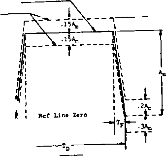 (A) gs : = KOSCKAL DJPJtTIOH Fragility Packaged Shock 10 to SO 30 2 nTfJ/fi) MOTE: The tls history display shall include a time about 3Tjj long ith a pulse located approximately in the center. The peak acceleration magnitude of the trapesoidal pulse is A and Its dis>ation if Tjj. The measured acceleration pulse shall be contained between the broken line bo\.vidaries mnd tha measured velocity change ( nich my be obtained by integration of the acceleration pulse) shall be Яthin ten percent ef the ideal pulse wiiieh appreyimfttely equali 0=9 A g (гт-Т^-Тр). The integration to determine velocity change shall extend from 0.4T. before the pulse to O.ITn after the pulse. Rise (Tp)and fall ITfi times shall be less than or equal to O.lTj. FIGRJRE 516.4-5. Trapetoidal.shock pulse confiKygatien and its tolerance limits. KCTHOD 5ie.4 d. Rationale. Levels for this test were set by considering how a field aqui; ngnt item might conracnly be dropped. (For exanple, a light equipment item might be carried by en* san chest high; thxm, it could drop 122 cm.) Field data have eho > that a typical piece of nan-portable equiiRiient will be droi >ed from heights up to 122 cm (48 inches) an average of four to six tines during its life cycle. 1Ъе 2e-drop requirement exists to Insure that each vulnerable position (faces, edges, and comers) of a typical test item receives on lopact. 1-3.7 Procedure V - Cr?- ь > a. Applications. Procedure V is for equipnent, mounted in an air or ground vehicle, that could break loose from its mounts and present a hazard to vehicle occupants. It is intended to verify the structural integrity of equipment mounts during sinulated crash conditions. The shock machine is set to a maximum acceleration level (AJ below the anticipated failure level. The approximate pulse duration is determinea as follows (see figure 516.4-5): -Sn 6 wS tjj) (Tp ar l Tjj assxsEd to be 0.1 Tj,) V = 0.5 (g) Ад, (CTp-Tp-Tg) (Tp and Tj are known) If an initial value for A does not exist, 15 gs may be vised. If no damage occurs, then Ад, will be increased incrementally vtfiile the maximgr. test item velocity change is held constant until damage to the test item occurs. This will be established as the test items critical acceleration fragility level. d. Rationale. Test levels used in this procedvire represent the correlation of the best information currently available from research and experience. If more applicable test level data become available, tbey should be used (reference d). 1-3.6 icedyg IV - Transit ФгОо a. Application. Procedure IV is Intended for equipment in its transit or conbination case as prepared for field use (caa*ried to a conbat situation by man, truck, rail, etc.). It is xjsed to determine If the teat item is capable of withstanding the shocks normally induced by loading and unloading of equipment. b. Ttogtriction**- Procediire IV is not intended for shocks encoisitered in a normal logistic shipping environnent as experienced by shipping containers. c. Test conditions. Test levels for this test are shown in table 516.4-11. The test item shall be tested in thesame conf igviratlon that is used in a conbat sltiBition. For test iteos under 45 Xg (1(Ю pounds), the 26-drop requirenent may be divided among up to five copies of the same test item if desired, in any cosbination. Toppling of the item following ignact wri, 11 occu* in the field and. therefare. toppling of the test item following Its initial inpact should not be restrained as long as the test item does not leave the required drop surfi
i edge. Drop on !bottom face or iskids; total of ;f ive drops NOTES: A. Drops Shall be made from a quick-release hook, or drop tester. The test item shall be so oriented that щ>оп inpact a line from the str\x;k corner or edge to the center of gravity of the case and contents is perpendicular to the inpact surface. B. With the longest dimension parallel to the floor, the transit or conbination case, with the test item within, shall be supported at the corner of one end by a block 13 cm (five inches) in height, and at the other corner or edge of the same end by a block 30 cm (12 inches) in height. Tfte opposite end of the case then shall be raised to the specified height at the lowest unsupported eorne- and allowed to fall freely. C. While in the normal transit position, the case and contents shall be subjected to the edgewise drop test as follows (if the normal transit position is unknown, the case shall be so oriented that the two longest dimensions are parallel to the floor): Edgewise drop test: One edge of the base of the case shal 1 be supported on a si 11 13-15 cm (five to six inches) in height. The opposite edge shall be raised to the specified height and allowed to fall freely. The test shall be applied once to each edge of the base of the case (total of four drops). D. The 26 drops may be divided among no тоге than five test times (see 1-3.6). b. Regtrletiong. Procedure У is not intended for equipment transported as cargo. (For cargo, use method 514.4) c. Test conditions. Use figure 516.4-1 as the test spectrun for the axis of test, provided that the effective shock duration Tg falls between 6 and 9 milliseconds for flight equipment and between 3.5 and 5.0 milliseconds for ground equipment. If Shock spectrvsr. analysis capabilities are not available, figure 516.4-4 may be used as an alternative to figure 516.4-1. d. Rationale. An aircraft crash level of 40 gs is based on the fact that, during a survivable crash, localized g levels can approach 40 gs. (Sround transportation vehicles are designed with a higher safety factor and, therefore, can sustain a rajch higher g level: this, the higher test level. 1-3.8 Procedure VI - Bench handling a. Appl i cat ions. Procedure VI should be used for equipment that may experience bench or bench-type maintenance. It is used to determine the ability of the test item to withstand the usual level of shock encountered during typical bench maintenance or repair. b. Restrictions. Procedure VI should not be used if it can be demonstrated that the shocks from the transit drop test are of a higher level. It is considered appropriate for medium-to-1 arge test items that have a naxiraum dimension greater than approximately 23 cm (nine inches). (Small items will be tested to higher levels during transit drop.) c. Test conditions. The test item shall be raised at one edge four inches above a solid wooden bench top or until the chassis forms an angle of 45° with the bench top or until point of balance is reached, whichever is less. (The bench top must be at least 4.25 cm [1.675 inches] thick.) A series of drops shall be performed in accordance wri.th II-3.6. d. Rationale. The heights used during this test were set by examining the typical drops that are comnonly made by bench technicians and assenbly line personne1. 1-3.9 Procedtjre VII - Pyrotechnic shock a. Appl ication. Procedure VII is intended for equipment to be subjected to shock from explosive devices. The shock can be characterized as an oscillatory transient, writh significant frequency content from 100 to 10,000 Hz, which decays to a few percent of its пахimunn acceleration in 5 to 15 milliseconds (reference b). The shock response spectrum often exceeds several thousauid gs at frequencies above 1,000 Hz (for 0 = 10). This ргосебш<е also applies to situations which may yield shocks of сопрагаЫе severity, such as atmospheric re-entry or water entry of missiles and high-velocity aerodynamic buffeting of high-performsmce weap>on systems. b. Reatrlctiona. This test procedure will not be required along any axis for which both the following are satisfied: (1) the test spectrum from a random vibration test (see I-3.3b) or a functional shock test exceed this spectrum requirement and (2) if the test spectrum requirement above the frequency range specified for the random vibration or functional shock test does not exceed g valtjes cf C.B X, vdtere f is the frequent in m. (The 0.8 x acceleration limit corresponds to apppQxiffiBLtely 19.7 cm/sec spectral velocity. A basis for use ef velocity as a criterion of serverity is given in reference e. The value of 19.7 cm/sec is selected because of limited observations (unpid>lished) that military-quality equipment does not tend to exhibit shock failxires below a response spectrum velocity of 100 in./sec.) c. Test conditions. Field ssasiired data cr data obtained from a siinilaF environment using appropriate dynamic sealing (reference b, vol, VI), will be used to define the shock test response spectnsn requirement along each of three orthogonal axes. Measxired data will be converted into test requirements in accordance with the guidelines outlined for the functional test conditions, 1-3.3, with two exceptions: (1) iSaasured or enpirical 1 у sealed data will always be required to determine the test response spectrusn. (2) The allowed duration for the test shock time history used for response spectrun analysis can be 20 milliseconds or less, unless a longer duration can be Justified by applicable data. d. Rationale. This procedure general ly confor-ns to r-equiremBnts for pyrotechnic shock testing in MIL-STD-1S40 for space vehicles. The pyrotechnic type shock test typically requires that the equipment to be tested be subjected to an intense, high-frequency oscillatory distxirbance. An attenpt to meet the test response spectrvm using a single acceleration pulse will usually result in a severe overtest at the 1оявг fFsqueneies in order ta meet the high-freqiiency requirements. 1-3.10 Procedure VIII -Rail inpact a. Ptsoose of test. Procedure VIII is intended to test equipment that will be transported by rail; to determine the effect of normal railroad car inpacts that occur during rail shiixnent, and to verify the structural integrity of the test item and the sdeqiacy cf the tiedcvn system and the tiedoMi proeedvs>es. Al 1 test items shal 1 be tested at their mipcinun gross weight (fully loaded) rating unless otherwise specified in the transportability requirements for the item. b. Restrictions. Procedure VIII is not intended for the separate testing of small, individually packaiged pieces of equiiment that would normally be shipped (and tested) when ssounted on a pallet. 1 ... 29 30 31 32 33 34 35 ... 43 |
||||||||||||||||||||||||||||||||||||||||||||||||||||||||||||||||||||||||||||||||||||||||||||||||||||||||||||||||||||||||||||||||||||||||||||||
|
© 2026 AutoElektrix.ru
Частичное копирование материалов разрешено при условии активной ссылки |