 |
 |
 |
| Главная Журналы Популярное Audi - почему их так назвали? Как появилась марка Bmw? Откуда появился Lexus? Достижения и устремления Mercedes-Benz Первые модели Chevrolet Электромобиль Nissan Leaf |
Главная » Журналы » Preparation instrucnons requirements 1 ... 31 32 33 34 35 36 37 ... 43 ШГнию 516.4 s. Adjust the total eight of the car asseiablage (see above) to at least 114,000 kilograins (250,000 pouids) , b. Conpress the соцр1егз between cars to take up any slack. c. Set all of the air and hand brakes on the car(s) to be used. d. Secure any load in or on the car(s) to prevent sliding or shiftir.g: any movement greater than 5 cm shall be justification for retest. e. The end of the buffer car to be struck muet have a standard draft gear. Step 2. Mount the test item on the test car. The test car shall be equipped with standard draft gears and conventional underframes. The materiel developer is responsible for the development of transportation instruetlone, and shall coordinate these with, and obtain approval from the Military Traffic Management Consand Transportation Engineering Agency (МГМСГГЕА), well in advance of rail Inpact testing. Mounting of the test item ahal 1 incorporate the standard loading and bracing method as shovin in Section 6 of the Association of American Railroads (ААЮ Rules (soverni.ng the Loading of Department of Defer,as Materiel on Open Top Cara.s No exotic or xjnusual tiedown methods shall be used: any non-st idard loading and bracing muet be approved by the Military Traffic Management Command Transportation Engineering Agency (МТМСГГЕА), ATTN: MIT-TR, PO Box 6276, Ft Eustls. VA 23606-0276 (or its European equivalent) prior to testing. Substitute (dumv) test items must be of eqvial weight and weight distribution as the actual test item and similar in shape. The arrangement of the test item and its blocking arid tiedowTi to be tested shall be identical to that proposed and approved by МГМ7ГЕА (if non-standard). ThiS requirement is mandatory for all equipment developed for lise in the U.S. Equivalent European standards may apply for non-U.S. conmodltles. Step 3. Situate the test car between the buffer cars and the locomotive, and pull the test at least 65 rasters (2(30 feet) from the buffer car(s) alor a level section of track (a minimum distance to achieve the required locomotive speeds). Step 4. Position the knuckles of the buffer and test cars for coipllng. Step 5. Install a timing device to measixre the test car speed km/h) jiist prior to inpact with the buffer car(s). Suggested methods include electronic tlmirig (microswitches) and radar. The ше of torpedoes and a stopwatch is permissible but not recomnended because of the inaccuracies involved. Step 6. Push the test car toward the buffer car(s) and, by using the locomotives speedometer or other means, release the test oar №en the desired test speed is reached, thus allowing the test car- to freely inpact the buffer саг(в). NOTE: Any impacts below the required test speeds shall be repeated. Impacts above the required test speed shall be accepted providing the requirements of 1-3.lOe are satisfied. Retesting shall be aecomplighed with new tiedown material to eliminate additive effects and, if possible, a new test item. Step 7. Repeat Step б until the test car(s) has impacted the buffer car three times at the same end, once each at speeds of 6.4. 9.7 and 13.0 km/h (4. 6. and 8 mph) +0.8. -0.0 km/h. averse the test ear and repeat the 13.0 km/hr inpact. for a total of 4 inpacts. NOTE: Adjustments of the lading or securing mechanisms, or reconditioning of the bracing or items of securement are not allowed during the test. If the tiedowns or chock blocks become loose during the test, a decision to completely retest will be made by MTtCTEA or the test director. Step 8. P.epeat steps 1-7 for any other shipping orientation. Step 9. Record the pertinent information for each inpact. to include the following: a. Conplete test item identification. b. The number and speed of inpact. c. Observations of tiedowns. blocking, fittings, etc. d. Observations of the test items physical condition. e. Results of any operational checks. NOTE: Cargo requiring extraordinary attention, i.e.. nuclear, one-of-a-kind, high value, or key military equipment, may justify changes to the test procedure and criteria; these shall be identified by the developer or Progr-ajn Manager. ar.d approved by ths Conrander. Military Traffic Management Goranand Transportation bjgineering Agency (ШЖГтО, ATTN: MTT-TR, PO Box 6276. Ft Exjstis VA 23606-0276 (or its European equivalent). II-3.9 Procedure IX - Catapult launch/arrested landing Step 1. Mount the test item to its vibration fixture as described in 514.4. I-4.2.5 for the first test axis. Step 2. Attach accelerometers described in 514.4 and other test instrumentation. Step 3. Conduct an operational checkout and visual examination in accordance with the approved test plan. Step 4. iфply Sine bursts to the equipgaent In the first test axis. (Each burst represents a single catapult or landing event.) Each burst should be follo iied by a rest period to prevent unrepresentative effects. The test item should be operated in its appropriate operational mode *iile the bursts are applied. Step 5. If the equipaant has not salfunctioned dupir.g testir.g. conduct an operational checkout and visual exanunatim in accordance mit Ue proved test plan. If a failure has occurred, it may be desirable to perform a thorough visual examination before proceeding with the operational checkout to avoid initiating additional hardware damage. №en a failure occvms, the nature of the failure and corrective action along with the purpose of the test (engineering Information or contractual conpliance) should be coriSidered in detainlrig whether to restart the test or contlnvie from the point of interruption. Step 6. Bepeat steps 1 through 5 for the second test axis. Step 7. ijocument the test as described in General Requirements. II-4 IMFOraHATION TO BE ВЕСОЮШ a. Test item Identification (manufacturer, serial nunber, etc.). b. Prior test methods to which the specific test item has been subjected. c. Pretest data required (see Qeneral Sequiresents). d. Procedure nvmber. e. Shock p>ulse selection, specifying shape, peak value, and duration; or measured data selected for use in conjvnetion nth tbe shock response spectrun outlined in procedure I and VI. f. (For procedure VIII only) Whether the rail impact shock pulse input and test item response are to be measured. g. (For procedure VIII only) Test item positioning wdth respect to the test car and whether packaging is necessary for the rail inpact test. h. Tenperature extremes (if the shock test is done in conjisx:tion with tenperature testing). 1. All instrvanentation and filtering used. j. Wsether operation durir.g ths test is required, mods of such operation, and if and how the operation is to be monitored. k. Loading and tiedowna. i. Failure criteria. KETHOD 516.4 m = 1 Z §i and s ~ i Z (gi-m) 1=1 i-l and when the sample valuea are assumed to be lognormal ly distributed E leg ii i=l and s 1 (log gj-ffi) The value of к in equation (1) is taken from table 516.4AI as a function of the пшЬег of sanple values n to yield a G value equal to the 95th percentile at least 50 percent of the tims. The \jss of this procedure becoraes highly sijspect for less than five data sasples. Any such use should be xmdertaken in asscciaticn with the approach reconmended in 1-3.3c when insufficient data are available for statistical analysis. The above process is repeated for each frequeney of the shock response spectrun. ТЪе resulting G values may be enveloped in a manner deemed appropriate by the responsible test organisation. TABLE 516.4A-I. Valuea of k. I/
W Owen, D.B. Factors for One-Sided Tolerance Limits and for Variables Sanpling.Plans. Sandia Corporation Monograph No. SCR-607. March 1963. APPENDIX 516.4A DEFINING TEST SHOCK FOR NQMifiU, OR иШЮТОШ, DISTRIBUTION OF Fia© DATA For each l/6th-octave (or more closely spaced) frequency, the test shock spectrun value G is given by G = m + ks (1) v.ere m* is the mean and s* is the standard deviation of the sasple values. When the n sanple values g are assuned on the basis of experience with Similar data to be normal ly distributed RETKOD 51S.4 nul-STD-aiOE 14 july 1888 METHOD 519.4 Gunfire vibratiok. aircraft SECTicaj I l-l PURPOSE...................... 519.4-1 1-2 EUVIBONMEWTAL EFFECTS............... 519.4-1 1-3 auiim.i*ffis FOR оегеншм1Ш tet PHOCEDuSK AND TEST CONDITIONS.......... 513.4-1 1-4 SPECIAL CONSIDERATIONS ............... 519.4-15 1-5 №a KKKMLkS ...... 519.4-15 SECTION II 11-1 APPARATUS ..................... 519.4-17 11-2 PBEPARATION FOR TEST................ 519.4-17 II-3 fsocedlses..................... 519.4-17 II-4 IKFQMiSATION TO BE ШСОШЕО............. 519.4-18 SECTION I 1-1 PiroPO. The gunfire vibration test is performed to assure that equipment moisited in an aircraft wdth Onboeod gwis сел withstand the vibration levels causec Ъу theoverpressure pulsus emitting from the gun nsjzzl€ 1-2 ENVIRONMEWTAL EHKhXTlS. The vibration resulting from repetitive gun blast pulses is two orders of magnitude above normal flight vibration levels. Gunfire vibration will cause the structure and equipment to respond in a violent manner. This response cai\ cause intermittent electrical contact, catastrophic eieetricai failures, hydraulic malfunctions, and structural fatigue failures. 1-3 GUIDELINES FOR DETEEMININQ TEST PROCEDURES AND TEST CONDITIONS. NOTE: The tailoring prooess as described in Section 4 of this document should be used to determine the appropriate tests and test variables. a. tePlication. This test applies to equipment Installed In aircraft that carry and fire onboard guns. b. Restrictions. Wien an item wi 11 be installed in a location where the gunfire vibration is less than normal flight vibration, no gunfire testing is reconmended. Use method 514.4. c. Sequence. This test should be conducted eeurly in the testing of the test item because of the very severe nature of the gunfire-induced vibration environnient. This is provided that the specific test item does not need to be tested in any other environmental test sequences. KEm>D 519.4 НОТЕ: Items tested in their vibration isolation rsDuntings should also pass the sninisus integrity requirements of method 514.4, 1-3.2.12. d. Testvariations. The test variables are vibration spectrxjn and intensity, and test duration. 1-3.1 Choiее of test SFOceduFCS. There is only ens prccsdure in this sssthcd. 1-3.2 Choice of related test conditions 1-3.2.1 Test spectrvin. Onboard gunfire produces vibration from three different sources: a. The overpressure pulses emanating from the gun ssszle b. The recoil kick of the gun on its moisits, and c. The motion of ammunition-handling mechanisms as the gijn is firing. Cf these, the one having the greatest effect at most equipssnt locations is the first. Therefore this test focuses on the vibration caused by the overpressvire pulses from the gun muzzle. The vibration enviironmant that occurs at a specific equipment location is a conplex conbination of broadband random vibration and intenae тшх-гоуювпа гвлшш vibration CP sinusoidal peaks at specific freqxjencies. (See 514.4, 1-4.2.2.) This vibration is a coBbination of forced and free vibration of the vehicles structure. The narroMband vibration - that is, the pressure pulses from a firing gxxi- is very intense and likely to have severe resonance effects on the aircrafts structure and equipment. These effects are hard to predict from a model and are better discovered by direct measurement. In the case of equipment that Is structural ly coupled to the gxm or its issunting structure, test spectra should alvss-s be derived froa asasvjred dat&. The significant vibration occurs at frequenelee betMeen 10 and 2000 Hz, 1-3.2.1.1 Measurlim gunfire vibration spectra. It is recomnanded that measiired data be taken at the equipment location of Interest while the onboard guns arc fired. These data should cover a frequency range of at least 10 to 2000 Hz. The data should be analyzed tising no greater than a IG-m coristant baridwidth filter- up tc 500 Sz and 2-Hz cor.5ta.nt bandwidth filter from 5<Ю Hz to 2000 Hz with a st.atletieal degree of frMdom of at least 50. These data should be recorded with the aircraft In actual flight becaxjee ground tests could result in data that arent representative of actual conditions. 1-3.2.1.2 Pre<;llct4nK, Bupfre, vpratiop ppectr . If measured data are not available, test spectra may be calculated using the following technique. NOTE: This techniqvie may over-predict those freqijenciee where the structure or equiproent responses become significantly nonlinear. Likewise, for those cases in v4iich the structure or equipment resonances coincide with the frequencies In the gunfire, the vibration response could be under-predicted (resonance on resonance). Figure 519.4-1 shows a generalized vibration si>ectrxsn for gvnfire-induced vibration. It is characterized by four vibration peaks and broadband random, e vibration peaks are at frequencies that correspond to the nominal gunfire rate and its first three harncnics. The specific values for each of the parasstsrs shcvat in figure 51S.4-1 can be determined from table 519.4-1 using the following distance factors. a. Vector distance (D). The vector distance from the nuzzle of the gui to the mean distance between equipment si4>port points as shown in figis 319.4-2. For configxjrations Involving oultiple guns, the origin of veetor и is deteiried fpc tha centroidal point of the gun muzzle as shown in figvire 510.4-3. b. (Km standoff distance (H>. The distance normal to the aircrafts surface as shown in figure 510.4-4. c. Depth parameter (R). The distance normal to the aircrafts skin to the equlpnent location inside the aircraft. Ii is isiisiown, use Kg = three inches (see figure 519.4-2). The vibration peaks bandwidths should be based on test data if possible. Vtien data are not available, the vibration peaks bandwidths can be calculated as: 3 3dB= Where: = the bandwidth at a level 3dB below the peak PSD level F = the fundamental frequency (Fj) or one of the harmonics: l, 2, 3, ° 4 For cases where the gxm firing rate changes during a development program, it is desirable to perform, sinusoidal sweeps writhin the proposed bandwidth for the fundamental and each harmonic. 1-3.2.2 Duration of test. The duration of the gunfire test in each of the three axes should be equivalent to the expected total amount of time the equipment will ex- Iience the environment in actual usage. This duration nay be consarv&tively sstimatsd by ssultiplyir.i th© expected nurabsr ef aircraft sortiM! in eiiiah guB!firir.g will occur by the meocimum amount of time that gunfiring can occur in each sortie. The nunber of sorties in which gunfire wrtll occur % ill be tied to planned aircraft training and combat utilization rates, but will generally be in the vicinity of 200 to о и ё и л Ц Р 3 -- Pi .1 т,. - т., 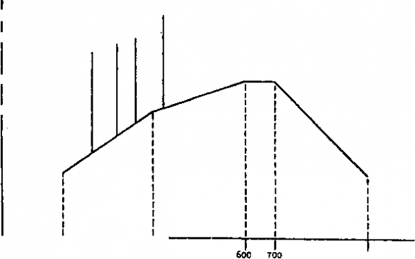 т-i-г-у-т F] Fj 300 Fu 2000 Frequency СИ ) FXCUE 519.4-1. flMitatiigttA.jpmnriLlmdUugdjribr tion вег tabLk 519.4-1. Suggested generalized parametric ecruationg for gunfiro-indueed vibration. 10 log Tj - 10 log (NFjE) + H + M + W+ J + Bj - 53dB 10 log = 10 log Tg + + 17 dB Where: N = .Maximum, nimfcer of closely spatced gx>ns firing together. For guns that are dispersed on the host aircraft, such as in wing roots and in gun pods, separate vibration test spectra are determined for each gun location. The vibration levels, for test purposes, are selected for the gtm that produces the maximum vibration levels. E = Blast energy of gun (see table 519.4-III). H = Effect of gun Standoff distance (see figure 519.4-4). M = Effect of gun location M = О unless a plane normal to the axis of the gun barrel and located at the nuzzle of the gun does not intersect the aircraft structure, then M = -6 dB. W = Effect of the weight of the equijeient to be tested (use figure 519.4-5). if weight of e<ixiiixnent is unknown, use W = 4.5 kilograms. J = Effect of equipments location relative to air vehicles skin (\jse figures 513.4-2 and 513.4=8). Bj = Effect of vector distance from fiun nuzzle to eauinment location (see figure 519.4-7). Fj Ounfiring rate where Fj = fxjndamental frequency from table 519.4-II. (Fg = 2Fi, Fg = 3Fi, F4 = 4Fi) T. - Teat level in P = Test level for fi equency F in g/Hz (where i = 1 to 4) . = Effect of vector distance on each vibration peak, P (see figure 519.4-8). NOTE: These equations are in metric units. The resultant dB values are relative to 1 g2/Hz. УЕШЮ 519.4 1 ... 31 32 33 34 35 36 37 ... 43 |
|
© 2026 AutoElektrix.ru
Частичное копирование материалов разрешено при условии активной ссылки |