 |
 |
 |
| Главная Журналы Популярное Audi - почему их так назвали? Как появилась марка Bmw? Откуда появился Lexus? Достижения и устремления Mercedes-Benz Первые модели Chevrolet Электромобиль Nissan Leaf |
Главная » Журналы » Preparation instrucnons requirements 1 ... 32 33 34 35 36 37 38 ... 43 MIL-fTD-810E U JILY 1989  л FIGURE 519-4-2. The diatangg saraagtr ?n1 and th* dgpth pgraegtgr (gg) WL-STO-eiOE U JULY 1989  О FIGURE 5\% 4-3- HuiUPlt KUna. ClOaClT KTOUPtfl- Я (Л о GUN BAFIREL AIRCRin- SURFACE Jl L Jl i J L-L. UJ 20 30 1 0 50 60 iro Glun Standoff PiiraMt*!*, h/e 80 90 FIGURE 519JCtfliLJuttluluatJLaa-iluaJajiucL lltlindofir pafiaaatiir. MIL-STD-eiOE 14 JULT 1088 Aircraft/POD Gun (Quantity) Location Firing Pate i Boiside (Rnds/Min) {Bnde/Sec)I Cspscity A-4 A-7D A-10 A-37 F-SE F-SF F-14 F-15 F-16 F-18 F-111 GCFOD 30 SLTJ-ll/A SUU-12/A suu-ie/A SUU-23/A NK12 (2) M31A1 (1) GAU-S/A (1) ! аАП-2В/А (1)I MBlAl (1) ! ше (2) ! Ю9 (1) MBlAl (1) SeiAl (1) M31A1 (1) MBlAl (1) M51A1 (1) (£430 (1) ((3UVU-8/A) (2AU-2B/A (I) AN-M3 (1) M51A1 (1) (3AU-4/A (1) ; Wing Boota ! Noae. Left Side: Nose : Nose i Nose ! Nose ! Nose ! Left side of ! Nose I 1000 4000 & 6000 2100 & 4200 6000 4000 & 6000 3000 3000 4000 & 6000 16.e ! 100/Qun I 66.6 & loo: 1020 35 & 70 : 1175 100 : 1500 66.6 & lOo: 638 Eight Wir.g Boot! 4000 & 6000 ! Left Wing Root i 6000 4000 & 6000 Top Center of J Nose Underside of Fuselage POD POD POD POD 50 50 66.6 & 100 66.6 & 100 100 66.6 & 100 5000 2400 ! 83.3 ! i 40 3000 & 6000! 50 & 100 1200 ! 19 6000 60C0 ! 100 i 100 300/aun 940 510 570 2084 1500 750 1200 1200 TABLE 519.4-III. Oun gpecHlcatloM.
I (1AD-2B/A i aAD-4/А i (3AU-8/A i !Ю9 MBlAl MCIl W.l2  .79 1.18 .50 .79 .79 .79 .79 .79 .79 Joules (J) X 0.7376 = foot-pounds 6,700 74,600 307,300 28,000 83.000 80,500 74,600 74,600 86,500 86,500 МЕТШО 519.4 MIL-STO-eiOE lA JI;LY 1989 № г 0 о и о 1 -I о о w- о о с ir- о о о ООО о о о о о о ч\в eOOftlVOOlAi-IOOMOpirvOOOi оо о ITS W о 1 - 1 - о о -I о о i.-. о н f-i <м Л; ja ---- <М .-I .-I f\ Equicment Test Weight (lbs) 3�7170000664373710 (Я Ilk С (О - -10 (а я 10 IV (С > .J fl II I-
0 10 20 30 bo 50 60 70 80 90 100 110 120 130 lUo 150 l60 Depth l>ara tor, R, (cm) FIGURE 519--l. Tiaat levial redtxitlon dua to dimth pmjfffmtmr. 00 о vo n  Distance Vectoir, D (cai) FIGURE 5t9.A-T. j2fi£i:ua£.Jk]ijL:AiarLJju&Ljajuu2liuiJlJLa£ OS С M> PI (О If f < 40 Hz, use .0 Иг curve 10(1 149 2 dibt n e Ve<.toiP, 0 (ош) 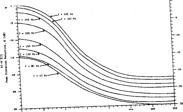 riOOBE 519.we. fl LttEe-QW iltoiUan.JMduaUflBU lULJlli*U ICL-STEbBlOK 14 JOLY lOeO 300 sorties. Tbe oaxioun gunfire tine per sortie can be deteinined from table 510.4- II by dividing total rounds per aircraft by the firing rate, men a gvn has more than one firir.g rate, the test should be run usir.g both firir.g rates, with test tisss at each firing rate based on the Mpected proportion of tine at ea firing rate in service. The guns carried by an aircraft are generally fired in short bursts that last a few seconds and testing should be i>erfoniied accordingly. For exanple, vibration should be applied for two seconds followed by an eight- to ten-seeond past period during which no vibration is applied. This two-second-on/eight-to-ten-second-off cycle Is repeated until the total vibration time equals that determined for the aircraft typ>e. This cycling will prevent the occurrence of unrealistic failure modes due to vibration isolator overheating in continvx>us vibration. Intermittent vibration can readily be achieved by several msauis including interrupting the shaker input signal and storing acceleration time history inputs on nagnetic disc or tape. 1-4 SFECIJO., gONSIPmiATIONS 1-4.1 Test interruptions. In the event of the occurrence of an unprogranmed test interruption, the test shal 1 be initiated from the point of interruption using the same specific test item. 1-4.2 Overteafe. Any interrtption in the test that results in a цк>1*е extresas exposure of the test item than required by the equipment specification should be followed by a conplete physical inspection of the test item and an operational check prior to continuation of teat. An engineering Jijdgnent ahal 1 be nade whether to continue teating wdth the overteated item, to obtain a new item, or to consider the test coleted. 1-4.3 Failure analvsia. All incidents where the test items do not neet the equipment operating requirements shall be analyzed to determine the cause and inpMt of such occurrences. Corrective actions shall be proposed or inplemented to meet performance requirements. 1-4.4 Spectr generation techniques 1-4.4.1 Pulse method. Ounfire vibration testing is done using pulses repeated at the gunfire rate. The generated spectra should have discrete acceleration magnitudes whose frequencies (f) correspond to the expression f = T\ty, vere f ia the baaic gunfire rate and т\ i,2,3,...K. The last integer (K) ia that value of for which f J is nearest to the naxlsun test freqiiency of 2000 Hz. The pulse teat speetrian shall be defined by ar. envelope that outlines the aaplltudes determined froBS the prediction method given in 1-3.2.1.2 or neasured data. 1-4.4.2 Broadband random method. Gunfire vibration testing can be done using a properly shaped broadband random vibration spectniB. It is characterized Ijy broadband random vibration wdth four vibration peaks that occur at the first three harmonica and the fundamental frequency of the firing rate of the onboard guna. 1 ... 32 33 34 35 36 37 38 ... 43 |
||||||||||||||||||||||||||||||||||||||||||||||||||||||||||||||||||||||||||||||||||||||||||||||||||||||||||||||||||||||||||||||||||||||||||||||||||||||||||||||||||||||||||||||||||||||||||||||||||||||||||||||||||||||||||||||||||||||||||||||||||||||||||||||||||||||||||||||||||||||||||||||||||||||||||||||||||||||||||||||||||||||||||||||||||||||||||||||||||||||||||||||||||||||||||||||||||||||||||||||||||||||||||||||||||||||||||||||||||||||||||||||||||||
|
© 2026 AutoElektrix.ru
Частичное копирование материалов разрешено при условии активной ссылки |