 |
 |
 |
| Главная Журналы Популярное Audi - почему их так назвали? Как появилась марка Bmw? Откуда появился Lexus? Достижения и устремления Mercedes-Benz Первые модели Chevrolet Электромобиль Nissan Leaf |
Главная » Журналы » Preparation instrucnons requirements 1 ... 33 34 35 36 37 38 39 ... 43 raL-STD-eiOE 14 JULY 1089 It has been experienced that the dynamic range required to produce and control this broadband random vibration is beyond the ability of most available vibration controllers. A way of wcrking arovmd this problem is to enter into the vibration controller the desired broadband random spectrum with its strong vibration peaks. At those frequencies which have the intense vibration peaks, sine teivee can be electronically added to the input to the vibration shaker aiiplifier. The airplitude of these sine waves should be such that the vibration levels produced at those frequencies is slightly less than the desired spectrun level. The vibration controller can niake the final adjustment to achieve ths needed test level. This method allows the gunfire test to be done in a closed loop with conraonly available laboratory test equipment. 1-5 R a. Sevy. R.W. , and E.E. Ruddell. Low and High Frequency Aircraft Gunfire. Vibration Prediction and Laboratory Sinmlation. affDL-TR-74-123. Decenter 1975. DTIC nunber AD-A023-619. b. Sevy, R.W.. and J. Clark. Aircraft Gunfire Vibration. AFFDL-TR-70-131. Novenber 1970. DTIC nurber А0-881-в79. c. Smith, L.G. Vibration Qial if ication of Ecpalpment feunted.in Turboprop Aircraft. Shock and Vibration Bulletin 51, Part 2. May 1981. NETHOD 519.4 GL-NFIBE VIBRATION. А1ВСЖАРТ SECTION II II-l APPARATUS. A random vibration source of sufficient capability to perform the Tequired test. Il-l.i Test getig. The test item shall be ir.stalled in a vibration fixture *ich sinulates the actual application configuration. To the extent practical, the vibration test setxip should incorporate actual mounting and isolation provisions fror the carrying aircraft. Fixture designs which utilize the naximum amount of platform structure possible will allow the test item to respond to the laboratory excitation m a manner more closely related to the actual field environmsnt. il-i.2 Controls. The aeeuraey of the instrurasntaticn for the gtmfire vibration test shall be as specified in method 514.4 for random vibration. For the broadband random method, the test tolerances will be as follows: at ffg, f, and +.6 dB. and at frequencies above 400 Hz +6 dB. If the controller used toshape the vibration spectra does not have sxjifficient capability to produce the required test spectrijm shape, the prod\x:ed spectrvin shall envelope the required spectrin. II-2 PREPAP.ATION FOR TEST Step 1. The test item shall be prepared in accordance with section 4, General Requirements. Step 2. Mount accelerometers following the practices for accelerometer nomiting. output averaging, and data analysis techniques outlined in method 514.4. II-3 PROCEDURES Step 1. Maunt test item on vibration shaker. Step 2. Operate the test items in accordance with equipment specif icatiQn.s. Step 3. Begin vibration exposure to the required test levels and spectra per I- 3.3. Step 4. Operate the test Item during vibration exposure in accordance smith equlpnent specif ications. Duration of vibration exposure shall be per I-3.2. Step 5. Operate the test item in accordance with the equlpnent specifications. ШтЗи 519.4 Step 6. Rotate test item to an axis perpendicrular to Just-conpleted test. Step 7. Repeat steps 1 through S. Step 8. Rotate test Item to the renainlng axis that is mutually perpendicular to the tvgo axes of test. Step 9. Repeat steps 1 through 5. Step 10. Document the test j>er 11-4. 11=4 INFORMATION TO BE RECORDED a. Test item identification (manufacturer, serial nxjnber, etc.). b. Test procedure nunber. c. Test levels, spectra, disations. d. Previous testing done using the specific test item(s) . e. Location of accelerometers used to measure vibration. f. Test results. g. Failiffe criteria. h. Analysis of each failure. i. Proposed corrective au:tlon8. j. Apa,lysls bandwidth. bETHOD 520.1 TEMFERArJEE. KuMIDiri. VIBRATION. ALTITODE page SECTION I I-l PURPOSE ...................... 520.1-1 1-2 ENVIRONMENTAL EFFECTS............... 520.1-1 1-3 GRJlDa.IlffiS FOR DETERMINlMa TEST PROCEDURES AND TEST CONDITIONS..........520.1-2 1-4 SPECIAL CONSIDEPTIONS...............520.1-20 1-5 REFERENCES..................... 520.1-24 SECTION Ii II-l APPARATUS ..................... 520.1-25 11-2 PREPARATIOK FOR TEST................ 520.1-25 11-3 PROCEDURES..................... 520.1-26 11-4 INFORMATION TO BE RECORDED............. 520.1-27 SECTION I I-l PURPOSE. The pxjppoae of this test is to identity failures that tenperature. humidity, vibration, and altitude can induce in aircraft electronic equipment either individually or in any conbination, during ground and flight operations. It may be used for other similar purposes. 1-2 ENVIBONMEП'AL KbKECTS. Studies have shown that thermal effects, vibrations, moisture, hxjmidity, and, in certain cases, altitude have the greatest effect on the life of aviation electronic equipmsnt in the operational environment. These foFcir g funetior.s collectively auscount for all but 12 percent of the environmgntal ly induced failwes in the field. (Of course other stresses such as sand and dust, salt fog. etc., are also significant and must be considered in a fully integrated test program.) Tenperature, hunidity, vibration, and altitude can interact to produce failures such as the following: a. Shattering of glass vials and optical equipment. b. Binding or slackening of moving parts. c. Separation of constituents. d. Changes in electronic conponents. e. Electronic or mechanical failures due to rapid water or frost formation. f. (bracking of solid pellets or grains in explosives. ieTKOD 520.1 14 JULY 1989 g. Differential contraction or expansion of dissimilar materials. h. Deformation or fracture of conponents. i. Cracking of surface coatings. J. Leakage of sealed conpartments. 1-3 GUIDELINES FOR РЕТЕЮДКИГО TEST rROCEDURES .AIJ? TEST OOMDITIOWS VCfTE: The tailoring process as described in Section 4 of this document should be used to determine the appropriate tests and test variables. a. Applications. This method is primarily intended for electronic equipnent mounted inside an aircraft. The procedures of this method can be used for engineering development, for siport of flight testing, and for qualification. b. Restrictions. Tnis method does not apply to electronic equipment transported as cargo in an aircraft. c. Sequence. Procedure I is intended to be used before final equipment designs are fixed. d. Test variations. The test variables are tenperature, hisnldlty, vibration, altitude, cooling airflow, electrical stresses, rates of change, and test duration. 1-3.1 Choice of test procedures 1-3.1.1 Procedure I - Engineering development tests. The engineering development test is used to find defects in a new design while it is still in the development stage. The test is failts e-ori6nt6d, raBanirig that the tester should hope to uncover as many defects as possible. A combined environment test le good for this purpose, since it does not require the tester first to predict vihlch stress states are most critical and then to tailor the test to enphasize those states. This test is generally accelerated by eliminating benign conditions or by using higher stresses than the item is likely to encoxmter in the field. 1-3.1.2 Procedure II - Flight or operation support tsst. This test is performed in prepaa*ation for, or dtjring, flight or operational testing. Its purpose is to minimize delays in the flight testing program due to environmental factors. This test is not accelerated; the damage accimulatlon in the test is no faster than in operational or in-flight testing. Therefore, development hardware can be interchanged between laboratory and flight or operational testing. This шевлв that when musual problems develop in flight or operatlor.al testing, ths squipaasr.t system can be brought into the laboratory to help identify any environjnental eontrlbution to the observed problem. 1-3.1.3 Procedure III - Qualification test. The qualification test is a formal test intended to demonstrate соиф!iance with contract requieisents. Generally, qualification testing is an accelerated test that enphasizes the most significant environmental stress conditions. The use of Procedure I of this test method for qualification is not reconnmended. The qualification test shall include the maximum anplitxjde of each stress amd any unique combinations of stress types that were found to be inportant in the engineering development testing of the test item. 1-3.2 Choice of related test eonditiong. 1-3.2.1 Procedure I - Bngineering develoTOBent test 1-3.2.1.1 Use the analysis outlined in 1-3.2.2, flight or operational support test, to determine realistic environmental stress levels, durations and rates of chainge. The more benign portions of the test profile can be eliminated for an engineering develonant test. Likewise the snplitixie of environmental stresses can be increaised to accelerate the occurrence of failures. 1-3.2.1.2 It is recomnended that a Procedin e II test of short duration be done when the test item is fairly mature arid its design stable. This would test the accuracy of the prejudgments made ais to wtiich environmental stresses are benign. 1-3.2.2 Procedure II - Flight-operational support test. Ibe eoiAined environment test conbines the environmental stresses of tenperature, vibration, humidity, and, if required, altitude and cooling airflow in a manner occurring in actual deployment. Mission profiles are used as the basis for formulating the environmental stresses. The failure data obtained from this test will help determine the corrective actions to be performed on the item to prevent failure in the operational environment. Generally, the confined envlrorjBsnt test simulates those environmental effects that оссш* for the majority of the deployment life. Depending гфоп available facilities, environmental stresses may be tested in combination or singly. 1-3.2.2.1 Environmental conditions for test. This section describes the step-by-step approach in the measLmement. prediction, and choice of fcrclng functions for a combined envirorjnent tsst. Figure 520-1 is a flow diagram, for generating a test profile, as described throughout this section. 1-3.2.2.2 Test cycle formulation. A test cycle is defined as a unit of time where several mission profiles are slnulated under different atmospheric conditions. A test cycle shall consist of at least three atmospheric segments of the sequence, cospcsed as follows: cold and dry, warm and moist, and hot and dry. Within each atmospheric segment of the test cycle, several different mission profiles may be simulated. A mission profile is defined as a Mach number-altitude-time history than an aircraft can fly. For exanple, a fighter aircraft may predominantly fly three different missions: air superiority, ground support, and interdiction; therefore, this aircraft has three mission profiles. Each mission profile is divided into flight phaises, such as takeoff, cruise, combat, lowrlevel penetration, etc. (figure 520.1-2). Durirg a test cycle, tenperature. vibration, hjaidlty, and cooling airflow shall be varied. Altitude ainulation may be NETTOD 520,1 с: т се <э о i 1 111 inwnwi л Л 1J - г  (ЯП 1 Н11ТиН  й
 
 FKSURE 520.1*1. Zi>al DCftmfi JtfiafiCBLbJLQnjClQ)LJ]LiaJSCaJl. MIL-STD-810E U Ji:LY 1989 с о (С -10 OirvvO О ir\ 1/\ о О 001г\0 -( гчемл ------ siOOr 001г\000 Л 000 ООО оооо о© : irvvo 000(MVOO</ni-i00(n о о ltv OOOir\ о о f-i >-i Л; ..3 о- VC а& о rw чо о :Л. О © Equipment Test Weight (lbs) 6�1710700669616110 Ul I- <л О -----г--г-г--г-1---,--1---,--,---,--1---,--1--т--г-т - О I---f*---1 -L-II-T--1-----1----------1----1--11 S * \-I-Т^чГ-1-I----------1-11 hill II I ITI I I I I I 11 3 \---r-[ ЧТ-г-г-г-г.. п /г ----1--11 г I I I [ I Т Т~ \ ШЛт f / 1 f I э I г I I г psTl Г - ! f * ° aJLrcraft fuieelajje at D .= hi--j-t-[ -j- -ri о I- \ I 1 I г г I I I г I 1 ,ц I I I I 1 III III I H tj I 1 I 1 L I I Nl- I I 1 I L 1 I ;э \--f-f--1--f--f----h-f--T*---h-1--H-------1-I 10 L I I L L L L I I I I I 11 (i> Г I I Г 11 I Г I 1 J~ Л 1 tc \ 1. 1- I I I I [ -4---5eaeita e..j rlll[fllll lllil II) > I I 1 >--h I- \ I 11---1--1---f--f--4--I-H > I I I I I I I I I I I I 1 I 1 1 I I .J 20 I--j-1--{-\--{-j---j--{---j--}---j--{---{-j-----}-j I- I \--у-у--у-У---4--К I 1---U I --4-----4--1-I D I I 1 I T I 1 T L L I t 1 I I 1 10 20 30 bo 50 60 70 ЬО 90 100 1.10 120 130 ll 0 150 l60 Depth 11>вгва 1(вг, Rs (cn) FIGURE 519 lBALJfiXELLXttlllBJULSIl.JlUS.Afi-lllUlUl-iW[Ulfi£ 6999999� Tj level ? 30 Нг 4 2кИг level 9 300 Hit level f> 600 Hit 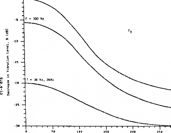 r- 0 -Г-r-I--r-1-?o Dlet nce Vector, D (cii) 1Л FIGURE 519.A-T. Cfiыaaafi.JJLлШлiJлttJлIfiLJ(lДйJloиliLxlJUlJйдaй^ :Л 00 с 1 ... 33 34 35 36 37 38 39 ... 43 |
||||||||||||||||||||||||||||||||||||
|
© 2026 AutoElektrix.ru
Частичное копирование материалов разрешено при условии активной ссылки |