 |
 |
 |
| Главная Журналы Популярное Audi - почему их так назвали? Как появилась марка Bmw? Откуда появился Lexus? Достижения и устремления Mercedes-Benz Первые модели Chevrolet Электромобиль Nissan Leaf |
Главная » Журналы » Preparation instrucnons requirements 1 ... 34 35 36 37 38 39 40 ... 43 If IF < 40 He, u9 40 Нг curve tUD PI 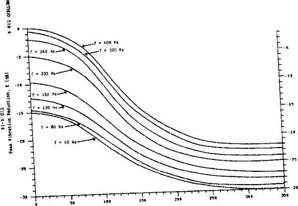 0lBV, ftO VetBtor, D ( >) nmn. 300 sorties. The naxinum ginifire tine per sortie can be determined from table 510.4-II by dividing total rounds per aircraft by the firing rate, wiien a gui has more than one firir.g rate. th@ tsst should be тлзл usir.g both firir.g rates, with test tias at each firing rate based м the expected wopertion of tiBae at firing rate in service. The guns carried by an aircraft are generally fired in short bursts that last a few seconds and testing should be performed accordingly. For exanple, vibration should be applied for two seconds followed by an eight- to ten-second rest period dwing which no vibration is applied. This two-second-on/eight-to-ten-second-off cycle is repeated until the total vibration time equals that determined for the aircraft type. This cycling will prevent the occurrence of unrealistic failure modes due to vibration isolator overheating in continunus vibration. Intermittent vibration can readily be achieved by several means including interripting the shaker input signal and storing acceleration tine history inputs on magnetic disc or tape. 1-4 SFETI.AL COKSIDERATIONS 1-4.1 Test interruptions. In the event of the occurrence of an unprogramnad test interruption, the test shall be initiated from the point of interruption using the same specific test item. 1-4.2 Overtest. toy intemtion in the test that results in a more extreaa exixjsutre of the test item than required by the equipment specification should be followed by a conplete physical inspection of the test item and an operational check prior to continuation of test. An engineering Judgment shal 1 be nade whether to continxje testing with the overtested item, to obtain a new item, or to consider the test conpleted. 1-4.3 Fai lure .analysis. Al 1 incidents where the test items do not meet the equipment operating requirements shall be analyzed to determine the cause and Inpact of such occiirrences. Corirective actions shall be proposed or inplemented to meet performance requirements. 1-4.4 Spectrum generation techniguss 1-4.4.1 Pulse method. Gunfire vibration testing is done using pulses repeated at the gunfire rate. The generated spectra should have discrete acceleration magnitudes whose freqxjencies (f) correspond to the expression f = nf ; where f is the basic gunfire rate and n 1, 2, 3, ... K. The last integer (K) is that value of for which f is nearest to the maxinun test frequency of 2000 Hz. The pulse test spectriai shall be defined by an envelops that outlines ths asplltudss deterssined from the prediction method given in 1-3.2.1.2 or measured data. 1-4.4.2 Brofidband random method. Gunfire vibration testing can be done using a properly shaped broadband random vibration spectrun. It is characterized by broadband random vibration wdth four vibration peaks that occur at the first three harmonics and the fundamental frequeney of the firing rate of the onboard guns. It has been experienced that the dynamic range required to produce and control this broadband random vibration is beyond the ability of mast available vibration controllers. A way of working aoovmd this probleffl is to enter into the vibration control Igr the desired brcadbsnd random spectrum with its stror! vibration peaks. -At those frequencies which have the intense vibration peaks, sine waves can be electronically added to the input to the vibration shaker amplifier. The anplitude of these sine waves should be sxx;h that the vibration levels produced at those frequencies is slightly less than the desired spectrum level. The vibration controller can make the final adjustment to achieve the needed test level. This nethGd allows the gtDifire test tc be done in a closed loop with coniuDnly available laboratory test equipment. 1-5 HKbKHHJJCES a. Sevy, R.W. , and E.E. Ruddell. Low and High Frequency Aircraft Gunfire. Vibration Prediction and Laboratory Simulation. AFFDL-TR-74-123. Decenber 1875. DTIC number AD-A023-ei8. b. Sevy, R.W., and J. Clark. Aircraft Gunfire Vibration. AFFDL-TR-70-131. November 1970. DTIC number AD-881-879. c. Smith, L.G. vibration Qualification of Equipment .Mounted in Turboprop Aircraft. Shock and Vibration Bulletin 51, Part 2. Sfey 18S1. МЕТЮО 519.4 GUNFIBE VIBRATIOK. AIRCRAFT SECTION II II-l APPARATUS. A random vibration source of sufficient capability to perform the T equired test. Il-i.l Test setxm. The test item shall be iriStalled in a vibration fixtjpe *iich simulates the actual application configuration. To the extent practical, the vibration test setim should incorporate actual mounting and isolation provisions fror the carrying aircraft. Fixtiire designs vhich utilize the maximum amount of platform structure possible will allow the test item to respond to the laboratory excitation in a manner more closely related to the actual field environment. II-1.2 Controls. The aocuraey of the instr-vsnsntation for the gunfire vibration test shall be as specified in method 514.4 for random vibration. For the broadband ramdom method, the test tolerances will be as follows: at f f2, f3, and tP << frequencies above 400 Hz +6 dB. If the controller used toshape the vibration spectra does not have sufficient capability to produce the required test spectrum shape, the produced spectrisn shall envelope the required spectrym. II-2 РВЕ?АРАТ10К FOR TEST Step 1. The test item shall be prepared in accordance with section 4, General Requirements. Step 2. Mount accelerometers following the practices for accelerometer mounting, output averaging, агЛ data 3r.alysis techniques outlined in method 514.4. II-3 PROCEDURES Step 1. MDunt test item on vibration shaker. Step 2. Operate the test items in accordance with equipment specifications. Step 3. Begin vibration exposure to the required test levels and spectra per I- 3.3. Step 4. Operate the test item during vibration exposure in accordance vw.th equiient specifieations. Duration of vibration ёЗфовШе shall be per I-3.2. Step 5. Operate the test item in accordance with the equipment specifications. Step 6. Rotate test item to an axis perpendicular to Jijst-completed test. Step 7. Bepeat steps 1 through *?. Step S. Rotate test item to ths remaining axis that is mutually perpendicular to the two axes of test. Step 9. Repeat steps 1 through 5. Step 10. Document the test per II-4. II-4 IKFORM&TIOK TO BE REOORDED a. Test item identification (manufacturer, serial nvnber, etc.). b. Test procedure number. c. Test levels, spectra, durations. d. Previous testing done using the specific test item(s). e. Location of accelerometers ijsed to measure vibration. f. Test results. g. Failure criteria. h. Analysis of each failure. i. iroposed corrective actions, j. Analysis bandwidth. METTOD 520.1 таШАТиШ, HUMIDITY, VIBRATION, ALTITUDE РАЖ SECTION I I-l PURPOSE ...................... 520.1-1 1-2 ENVIRONMENTAL EFFECTS............... 520.1-1 1-3 OUIDELINES FOR ОЕГГЕРЛПШМа PROCEDURES AND TEST CONDITIONS..........520.1-2 1-4 SPECIAL CONSIDERATIONS...............520.1-20 1-5 REFERENCES ..................... 520.1-24 ACTION Ii II-l APPARATUS ..................... 520.1-25 11-2 PPRPARATION FOR TEST................ 520.1-25 11-3 PROCEDURES..................... 520.1-26 II-4 INFORMATION TO BE RECORDED............. 520.1-27 SECTION I I-l FJRPOSE. The purpose of this test is to identify failures that teneerattJre, hVBnldity, vibration, and altitude can induce in aircraft electronic equipinent either individually or in any combination, during ground and flight operations. It may be lised for other similar purposes. 1-2 ENVIROwMEKTAL EFFECTS. Studies have showi that therasl effects, vibrations, moisture, hunidity. and, in certain cases, altitude have the greatest effect on the life ef aviailQn electronic equipment in the operational environment. These forcing functions collectively account for all but 12 percent of the environmentally induced failures in the field. (Of course other stresses such as sand and dust, salt fog. etc.. are also significant and must be considered in a fully integrated test program.) Tenperature. hxjmidity. vibration, and altitude can interact to produce failures such as the follosslng: a. Shattering of glass vials and optical equijnent. b. Binding or slackening of moving parts, e. Separation af constituents. d. C!hanges in electronic components. e. Electronic or mechanical failures due to rapid water or frost formation. f. Clacking of solid pellets or grains in explosives. .VETHOD 520.1 14 JULY 1989 g. Differential contraction or expansion of dissimilar materials. h. Defornation or fracture of conponents. i. Cracking of surface coatings, j. Leakage of sealed conpartments. 1-3 GUIDELItreS FOR DETERMIWING TEST,PROCEDURES AND TEST 001g)ITI0NS гГОТЕ: The tailoring process as described in Section 4 of this document should be used to determine the appropriate tests and test variables. a. ApDlications. This method is primarily intended for electronic equipment mounted inside an aircraft. The procedures of this method can be used for engineering development, for support of flight testing, and for qualification. b. P.agtrictior.g. This msthod does not apply to electronic equipment transported as cargo in an aircraft. c. Sequence. Procedure I is intended to be used before final equipment designs are fixed. d. Test variations. The test variables are tenperature, hunidity, vibration, altitvide, cooling airflow, electrical stresses, rates of change, and test duration. 1-3.1 Choice of test procedures 1-3.1.1 Procedure I - Engineering development tests. The engineering development test is used to find defects in a new design i4iile it is still in the development stage. The test is failure-oriented, meaning that the tester should hope to uncover as many defects as possible. A combined environment test is good for this ргд>роае, since it does not require the tester first to predict which stress states are most critical and then to tailor the test to enphasize those states. This test is generally accelerated by eliminating benign conditions or by using higher stresses than the item is likely to encOimter In the field. 1-3.1.2 Procedure II - Flight or operation support test. This test is performed in preparation for, or during, flight or operational testing. Its purpose is to minimize delays in the flight testing program due to environmental factors. This test is not accelerated; the damage accuaulation in the test is no faster than in operational or in-flight testing. Therefore, develonent hardware oan be interchanged between laboratory and flight or operational testing. This means that when unusual problems develop in flight or operational testing, the equipment system can be brought into the laboratory to help identify any environmental contribution to the observed problem. 1-3.1.3 Procedure III - Qualifleatlon test. The qualification test is a formal test intended to demonstrate conpliance with contract requirements. Generally, qualification testing is an accelerated test that enphaisizes the most significant environnental stress conditions. The use of Procedure I of this test method for qualification is not recommended. The qxial if ication test shall include the maximum anplitude of each stress and any vnique combinations of stress types that were found to be inportant in the engineering development testing of the teat item. 1-3.2 Choice of related test conditions. 1-3.2.1 Procedure I - Engineering development test. 1-3.2.1.1 Use the analyaia outlined in 1-3.2.2, flight or operational support test, to determine realistic environmental stress levels, durations and rates of change. The more benign portions of the test profile can be eliminated for an engineering development test. Likewise the anplitude of environmental stresses can be increased to accelerate the occurrence of failures. 1-3.2.1.2 It is recomnended that a Procedure II test of short dxiration be done when the test item is fairly mature and its design stable. This would test the accuracy of the prejudgments made as to which environmental stresses are benign. 1-3.2.2 Procedure II - Flight-operational support test. The conbined environment test conbines the environmental stresses of tenperature, vibration, humidity, and, if required, altitude and cooling airflow in a manner occurring in actual deployment. Mission profiles are vised as the basis for formulating the environmental stresses. The failure data obtained from this test will help determine the corrective actions to be performed on the item to prevent failure in the operational environment. Generally, the conbined environment test simulates those environmental effects that occur for the majority of the deployment life. Depending upon available facilities, environnental stresses may be tested in conbination or singly. 1-3.2.2.1 Environmental conditions for test. This section describes the step-by-step approach in the meaain?enient, prediction, and choice of forcing functions for a conbined environment test. Figure 520-1 is a flow diagram for generating a test profile, as described throvjghout this section. 1-3.2.2.2 Test cvcle formulation. A test cycle is defined as a unit of time where several mission profiles are simulated under different atmospheric conditions. A test cycle shall consist of at least three atmospheric segments of the sequence, conposed as follows: cold and dry, % arm and moist, and hot and dry. Within each atmospheric segment of the test cycle, several different mission profiles may be slnulated. A mission profile is defined as a Mach number-altitude-time history than an aircraft can fly. For exanple, a fighter aircraft may predominantly fly three different missions: air superiority, ground ai9port, and interdiction; therefore, this aircraft has three mission profiles. Each mission profile is divided into flight phases, such as takeoff, cruise, combat, low-level penetration, etc. (figure 520.1-2). During a test cycle, tenperatine, vibration, hunidity. and cooling airflow shall be varied. Altitude ainulation may be о c; 3 i GO 00 о 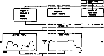
tIMI CMCiavi тяг ] Г gjsl pin nin ф Г^Тсг]Г] □ 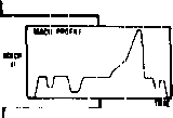 4г яквм Л 1 J - tl* л jjiiBiaBic b-n:ir   WIIIT .BiL FIGURE 520.1-1. lisat juaiJ[llajmMatJLQjiuClQ3LJlliaecM. Test Cycle Ituraspherlc Segnent 1 Atmospheric Seisment 2 Atmospheric Sei5m nt 3 oi m о (Я Mission Profile 1 MJLsaion Profile 2 Mission Profile 3 Mission Profile 1 Mission Profile 2 Mission Profile 3 Mission Profile 1 Mission Profile 2 Mission Profile 3 Phase 1 Takeoff Phase 2 Cruise Phase 3 Combat (- ib ю i-00 о PIGURK 520 .1-2. Itottoa up vieif of a test eycHe. 1 ... 34 35 36 37 38 39 40 ... 43 |
|
© 2026 AutoElektrix.ru
Частичное копирование материалов разрешено при условии активной ссылки |