 |
 |
 |
| Главная Журналы Популярное Audi - почему их так назвали? Как появилась марка Bmw? Откуда появился Lexus? Достижения и устремления Mercedes-Benz Первые модели Chevrolet Электромобиль Nissan Leaf |
Главная » Журналы » Preparation instrucnons requirements 1 ... 36 37 38 39 40 41 42 43 test item to reach thermal stability. As would haen in actiial usage, the mass of the test item will determine how close the test item urll 1 get to the Inposed tenperature. ЙЕПЮС 520.1 The test should reproduce ssssursd transient exactly. If this is net possible, tolerances should be calculated individmlly for each transient type. Tolersnces should be narrow for stresses the equipment is more sensitive to, and vice versa. The basis for calculations shall be the requirements docunent - stress values that the equiiHoent nust be able to withstand during normal operation - provided the actual measured stresses of the electrical system do not exceed these limits. In tha absence of ary other nieariS of simulating power line trarbSients, the aqulpmsnt shall be ccled on ile *rforssance **i*msnts are cs&de and then bacnSd off for five minutes prior to the normal turn-on at the end of each ground park idiase. 1-3.2.3 Procedure III - Qualification test. Qualification can be acconplished either with a single test which combines all the appropriate environmental stresses or with a series o£ separate tests. It is not reconnended to run all environmental stresses in separate tests. Snhen the гге of separate envircniaental tests is selected, the following single and ccniined environment stress tests are recommended: vibration; a combined tenperatxire, altitude, and hunidity test: and a combined siplemental cooling airflow with hunidity, tenperature, and mass flow rate as test parameters. The following guidance is recomnended for each separate test. 1-3.2.3.1 Vibration-stress. Use the test conditions and diiratlons recosnended in method 514 for qualification testir.g. 1-3.2.3.2 Tenperature-altitude-huniditv test. This test is for the conditions Inside an eqvilpment bay or coclqpit. Identify the maxinun and mlnimun tenperatures to be experienced in anticipated deployment by the item to be tested. Identify the maxlmm and minimum tenperature under which the test item is expected to operate. These teIфeraturёs can be obtained from the analysis outlined in 1-3.2.2 of TT Tt . .. V a a a1.. j . .4- > #n 1 4 оК. .sKlAfl КОП t-V mw KOf\ 1- J#a VWW M 4S л л e UKw l ЛК MM AJrC ШШШ ewW WWWVM A , моты A WB W .V. * w WMMd w .w. * VT and fig\s 520л-5 can be xsed. The values in tables 520.1-V and 520.1-VI are based on measured data and are representative of extreme tenperature conditiona (air tenperature. not equipment temperature). Therefore, there is reasonable confidence that these test levels will sufficiently stress the test itesL The maxinLm altitude to be experienced by the item to be tested should come from the analysis outlined in 1-3.2.2. Often the altitude (air pressure) inside a cockpit or equipment bay Is different from that outside the aircraft because of cabin pressurizatlon. If an analysis has not been done, use maxinun flight altitude or. If unknowm, use 16 km (52.500 ft.). anticipat.ed extreme-Gase кроешь dxjrstions. It is not recoamended to force the tabu: S20.1-IV. Cc>nfcin<id environn nt test cvcle atructur-a.
1 1 о о Determine from aircraft mission profile. ov Thm nunlMr of different missions in each segment is determined In accordance with 1-3.2.2.2. irhese vuluies are baised upon historical eicerience, reference f. - 2 I trt H О I - 00 о 1 tt > о 1 SB Ч Q О О О i i I i in in ООО I i < in in IT) i I i i i 0 о in m 4> Ю  о § to о ; Ti№i: TEiMP ; ! ! ! ALTIirUDE i nmilDimr I IEMDP Ж сооыш AIR 1 BQOiwewr ! MASS FliOW 1ШЕ !HUMIDITY! OWOVF ! 01ЛГ, CO eo eo 150 210 210 240 Return to tlnik i ro Tmin 1min oPmln max ]EtH mix RH iraln Tml-n Tmlin Imln RH iMOi[ RH Olff Oil Oiri On On On Off Off Oni On The aiaount oJF timB to ranp tenpiraiture Is depcindenib \xpon the test facility changtt rate aind l8 n<9t covjnt (!l in Umi foui* hours of the test cycle. < о 1-5П The hvjnadity stress is based upon reasonable levels that can be experienced in actual tjsage. Unless analysis such as outlined in 1-3.2.2 shows that the equipment bay or cockpit environment are significantly more or less humid, the level shown in table 520.1-V is reconnended. 1-3.2.3.3 Supplemental-cQQling-air humidity, mass flow rate, and,temperature test. This test- is for supplemental cooling airflow that flo*e dlrestly through an equipment system The temperature, htmidity and mass flow rate can be determined from an arialysis as outlined in 1-3.2.2 of procedure II. If such an analysis is not available, the levels in table 520.1-V and combined as shown in table 520.1-VI and figure 520.1-5 are recomnended. 1-3.2.3.4 Electrical stress. Unless otherwise defined, use the electrical conditions outlined in 1-3.2.2.9.1 and 1-3.2.2.9.2 as applicable. 1-3.2.3.5 Test item operation. The item shall be operated throughout each test except vixen being exposed to maxinum and mininum tenperatures that occur in equipoent bays or the cockpit. If separate tests are conducted, the test item shall be tvB<ned cn and off using the same schedule as if the test sr.vironmsnts vssre all combined. 1-3.3 Test duration a. Procedгдe I. The test Should be conducted so that the test item experiences 300 to 600 mission hours of stress exposure. The rate of occurrence of defects in conjunction wdth schedule and cost generally determines the duration of an engineeri.ng development test. If few or no failures are occiHrlng; little new information is being generated as to how or where to improve the test item and the test should be terminated. b. Procedure .II. Test duration Shal 1 be sufficient either (1) to give the tester confidence that environinenta 1 actors will net cause significant problems dtiring the flight test program or (2) to resolve a problem that arises during flight or operational testing. c. Procedгдe III. Procedure III shall be conducted for ten test cycles per figure 520.1-5, or its equivalent (40 environmental stress hours writh 30 hours of equipnent turned on). This is somewsiat arbitrary, but refleets the duration of previous tenperature-altitude-hunidity tests. 1-4 SPECIAL CONSIDERATIONS 1-4.1 Test interruption. In the event of an unplanned test stoppage due to an event such as a facility failure, the following is recommended. If the item has not failed and there is no apparent damage to the test item, the test continues. If the test item vssLS damaged when the tinplanned event occurred, testing should not be restaned unti 1 it can be determined whether the stress combinations during the unplanned event are likely to occur in the deployment environment. Testing should be resuned at the point of interruption and failed test article(s) removed before beginning the next phase, unless the nature of the failure precludes any useful equipment operation. hip P lU.aOO neters - I0l,:32!i A4331-hp -, 5.2558:5 L ШЗГ . 11,000 meters <hip <20,000 meters 22,631.945 exp (1.73456-.0001576873 hp) hp >20,000 meters 216650 n ЗА.163 96650 + hp. 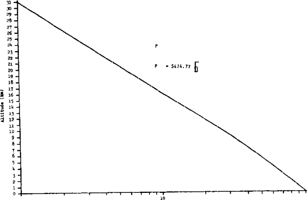 Preiiaure (kPe) FIGURE 520.1-4. Altitude v pressure. - 00 oo. о с с о с о Мах Husidity in Airflow Max Mass Flow Rate Minimum Tmax hum Tmin soak Equipment On Max Altitude - Toper- 3j -buffisoak Tain ЛТ > 5°C/mln UX CVWWA.*. BOURS FIGURE 520.1-5. puaiificatipp teat cyqic мвц. 520.1-22 8 г (Я 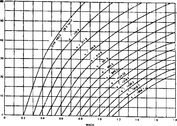 FIGURE 520. 1-6. unuaifi-jaCttMUCft-ia) ля funietln е: rji 00 о a. Sevy, R.W. Conputer Frogramfor Vibration .prediction, of jlRhter ДА. A Ц AJA----- ------- ----- ------- b. Hal 1, F.S. Vibration Test Level Criteria for Aircraft Equipment. AFWAL-TR-80-3119. December 1980. c. Lloyd, A.J.F.. Q.5. £>uleba, and J.F. Zeebenm, Environmental Control System (ECS) Transient.Analysis. AFFDL-TH-77-102. October 1977. d. Dieckmann, A.C., et al. Development of IntegratedEnvironmental Control Systems Design for Aircraft. AFFDL-TR-72-9. May 1972. e. Quartz, I., A.H. Samuels, and A.J. Curtis, A Study of the.Cost Benefits of Mission Prof lie Testing. AFWL-TR-81-3028. 1981. t, BTBkhard, А.н= = et al= СШ?Г gvaitjation Program Final Report. iy!ViAL-TR-e2- 3085. g. F- 15 AFDT&E High-Tenperature Desert Test d C1 imatic Laboratory Evaluation. AFFtC-TO-75-19. October 1975. DTIC КшЬег AD В011Э45Ь. 1-4.2 Failure criteria. All incidents where the test item does not meet equipment operating requirements shal 1 be analyzed to determine the cause and inpact of such occuarrenees. Corrective actions shall be proposed or Inplemented as required to meet equipment psrfornar.es rsquirsssnts. 1-4.3 Chamber/sensor tolerances. The accuracy required in General Requirements applies for each stress measurement system The ability of a given test chanber to control to the specified Stress conditions Is a function of the chambers design and appropriate placement of transducers. Thus, in evaluating the test tolerances for amy given combined environment test, the test plan should clearly identify the placement of the stress measurement transducer relative to the test item. 1-4.4 Testjrof 11 e to 1 erances. The tolerances for each stress in each phase of procedure II can be derived from design specifications. For example, the design specification may call for a phase of cruise betwieen 20,000 and 30,000 feet. For ths tsst mission, this car. bs trar.slatsd into ar. altitude of 25,000 feet with a tolerance of +5,000 feet. 1-5 RiunsJiEWCES WETOOD 520.1 7EMPERATJEE. JflJMIDITY, VIBRATIOK. ALTITL4)E SECTION II II-l APPARATUS. The connbined environment test chamber(s) shall be capable of producing the required combinations of tenperature, altitude, humidity, random vibration, and cooling air nass flow. Ail instrumentation shall be able to meet the accuracy specified in section 4 of General Requirements. II-2 PREPARATIONJORJTEST- Select v*iich test procedure shall be inplemented. Identify if the test shall be a combined environment test or a series of single and appropriate environmental confcinations tests. Select which of the following steps are appropriate for the environmental Stresses being included in the test of interest. Step 1, For vibration testing in Procedure I or II, the individual equipment test itemCs) should be subjected to random vibration in either the aircraft vertical or lateral axis, whichever seems to offer the greatest potential from defect disclosure. If neither axis seems to offer a distant benefit, the test axis may be selected to suit facility convenience, when practical, diagonal vector vibration (vibration applied diagonally at a test ite.T. corner through Its center of mass, rather than along a single orthogonal axis) may be applied to provide multi-axis excitation using a single test seti. For Procedure III, conduct vibration test in accordance with method 514.4. Step 2. For tests that do not include vibration, mount test items in their normal orientation with the ground plane when the carrying aircraft is p>arked on ths grojnd. Step 3. For Procedures I and II, mount at least two vibration pickups to measure the vibration environment for each test item Fol low actices for the accelerometer mounting, output averaging, and data analysis techniques outlined in method 514 of this StaTiuard. Step 4. For test items that require supplemental cooling air, measure mass flow rate, hisnidity, and tenperature. Mount instrumentation so that these values are known as close as possible to where the air enters the test item(s). Step 5. Bay air conditions around the equipment shall be measured &s specified in (Seneral Requirenaents, 5.3.2. The air tenperature around the equipment under test shall be used to control this environmental Stress. Step 6. Mount himidity sensor to measure bay air hunidity. A single-point measurement is adequate as long as the measurement point is not shielded from the bulk conditions around the test item. 1 ... 36 37 38 39 40 41 42 43 |
||||||||||||||||||||||||||||||||||||||||||||||||||||||||||||||||||||||||||||||||||||||||||||||||||||||||||||||||||||||||||||||||||||||||||||||||||||||||||||||||||||||||||||||||||||||||
|
© 2026 AutoElektrix.ru
Частичное копирование материалов разрешено при условии активной ссылки |