 |
 |
 |
| Главная Журналы Популярное Audi - почему их так назвали? Как появилась марка Bmw? Откуда появился Lexus? Достижения и устремления Mercedes-Benz Первые модели Chevrolet Электромобиль Nissan Leaf |
Главная » Журналы » Preparation instrucnons requirements 1 ... 5 6 7 8 9 10 11 ... 43 -4.i7t 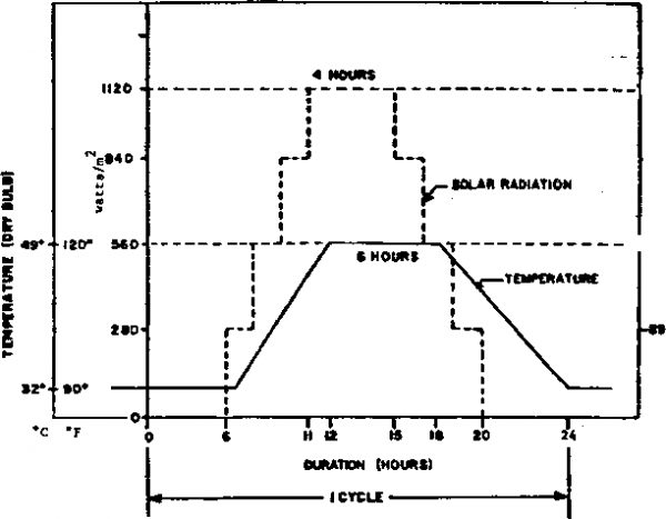 FIGURE 505.3-1 Simulated solar radiation cycle (Procedure I) 505.3-6 iieC -  TEST CYCLE TIMES (HOURS) FIGURE 505.3-2 TEST CYCLE DURATION (PROCEDURE II) IUb-L>-UlUlt 14 JULY 1S88 c. ConfKuratlon. Tb* teet itmm configuration abould ba tha aaaia aa ita configuration du*ing expoeure to solar radiation. The orientation of tha test itam relative to the direction of radiation will have a significant iB>act on tbe heating effects, as will its mounting (on supports or on a substrate of specified properties, e.g., a layer of concrete of specified thickness or a sand bed of certain reflectivity). d. AdditionalJtuidaxKje. Review the requiremanta docuamntCa). Apply any additional guidelinea appropriate. 1-4 gppcifb (XglPBBATTPTig 1-4.1 Failurs analysis (See General Sequiressnts. 5.2.7.) a. Procedure I. Both at peak tenperatxs and after return to atandard aabient conditions, the performance characteristics of the test item will not be altered to the extent that the test item does not meet its requireomnts. Actinic effects that do not affect performance, durability, or required characterlstios b. Procedure II. The performance and characteristics (such as color or other surface conditions) of the test item will not be altered to the extent that the test item does not nmet requirements. Actinic effects that do not affect performance, durability, or required characteristics will be recorded as obaervations only. Thm fading of colors could result in higher heating levels within the test IteaL 1-4.2 я ит>тп/ f.f testnformation requlred. The following Information is required in the test plan for adequate conduct of the tests of section II. a. Test item configuration and orientation. b. Test procedis. c. Location of tenperature sensors. d. Huiber of <les. e. Appropriate diurnal cycle (for procedure I). f. Spectral radiation of the source. g. Test item preparation (see II-1.2B). h. Test item operational requireaents (see 11-3.1, step 2). 1. Additional guidelines. МЕТЖл) 505.3 505.3-S a. AR 70-38. Heaearch. uevelopmnt. Test and Kvaiuation of wafceriel for f iimjt-pondij-og I 1 Augvet 157в. ШЬ-ЯТО-гЮ, Climatic Information to Determine Deajgn and Teat Beoulrementa Mllltarv Svateme EouiDment. О January 1087. c. gYH9Wtg 9? BagKgroyryj rteri l ог-ШЬ-5ТР-210В, Climalic jtfbfm.foT ill 11 taw EguiPinent. Bedford, MA: Air force (Cambridge Hesearch Laboratories. JanUu 1074. STIC nvnber AD~73C-508. d. NATO STAKAO 2805. Extreme Climatic Conditions and JXerived Conditions for Use in Deflninit Design/Test Criteria for NATO Forces Iteteriel. IsETHDD 505.3 505.3-е c. The volune of the test chaaber shall be a minlaun of 10 timaa that of the envelope volune of the teat item. d. The solar radiation aource erea shall be siich that the length and width of the teat item ahall be no more than ie-hali the аашв disansions of the 1в1ф bank and say be conposed of either radiant heat-producing Isssga (for procedure I) or lai that siaulate the solar spectrum (for procedta II or both I and ID. e. The irradiance shall have a maxinun intensity of 1120 Wa? (.lOX). and the radiation on the test item shal 1 be xsiiform to wlln 10% of the desired valxja, with the spectrai distribution given in table 505.3-II. га tb il effects only are to bs assessed, deviation froa this spectral distribution is permitted, but *Ы irradiance oust be adjusted to give an equivalent heating effect. In order to calculate thla adjvetaant. it ia necessary to know: (1) Tbe spectral reflectance or transadttanoe of Ute irradiated surfaoea, (2) The apectral energy distribution of the particular laaps being used (and also the effect cf any associated reflectors or glasses). The radiation ahall be directed onto the teat it n and shal 1 Irradiate the entire s\s*face of the test item facing the aolar radiation source. The value of 1120 Wv? Shall include any lETHDD 505.3 SECTIOH II II-l APPiffiATUS II-l.l T-t facility a. The reqfuired facility consists of a ehaariaer or aftbinet, auclllary instrtmentation, and a solar lanp bank. This a>eratue nust be capable of naintaining and monitoring required conditions of tenperature, airflow, and irradiation. b. For procedure I, the poaalble cooling effects of airflow over the teat specinans must be considered. Un airflow of as little as 1 si/s can causa a reduction in teaperature rise of over 20 percent. It is essential, therefore, to cMitrel and measure the rate of airflow. Aich should be as low as possible consistent with achieving satisfactory control of tenperatxire. Adjxsitmante of the tenperature within the enclosure and control of chanber gradients by suitable heating and cooling of the walls of the enclosrjre eliminate the need for high air velocities. The air velocity shall be maintained between 0.25 and 1.5 m/s {50 tc 300 ft/airJ. 14 JULY 1988 radiation refloated fron the test chanber walls and received by the test item, but it should not Include long-wave Infrared radiation emitted by the chanber walls. The radiation-measuring device shall be calibrated in the wavelength range of the test source radiations. TABLE 505.3-II Spectral ener<v distribution and permitted tolerance. Spectral Region CHARACTEBISriC I ULTRAV1(X£T VISIBIf I№RARED Banddth Irradiance Tolt O.SS te 0.32 to ! 0.40 to 0.78 pa 0.32 u m 0.40 um * б W/и? вЗ W/и? ! 517 to 004 W/и? ♦35% +25% i ♦10% ! 0.78 to : З.ООит 492 W/и? i +20% ЮТЕ: The amouit of radiation wavelength shorter than 0.30 j m reaching the Earths surfaoe is insignificant. f. The radiation source shall be located at least 76 cm (30 inches) away from any other surfaoe of the test item. 1.4 Kf. атлмчв (1) Tests conducted for degradation and deterioration of materials d\je to actinic effects, as wall as heat buildup within the test items, nust satisfy the full spectrun of table S05.3-II and may use one of the following acceptable radiation (a) Xenon arc or mercury xenon arc (used singularly) with suitable reflector. Cb) (kmblnation of high pressure sodixmi vapor and inproved mercury vmftar d.th suitable reiiectcrw. (c> High-intensity sultivapor, mercury vapor (with suitable reflectors), and inoandascent spot lamps. (d) Carbon arc lanps with siiitable reflectors. HOTB: Other oonblnations of the lanps listed above and in II-l.lg(2) below may be isMd if it is proven that the cosbinaticn produces the spectrua ef table 505.3-11. (3) Tests in which it is not sought to reprodijoe the suns spectrun may use the appropriate laspa from: JSraOD 503.3 U) Мвгсигу vapor 1ащт (internal ref lactor type only) . (b) Coiibination ot incandescent spot lanps and tubular-type asrctsy vapor lasps with external reflectors. (c) (ksdbinaticn of incsndescent spot laaps and nercuryi vapor 1швв mitt Internal reflectors. (d) Metal halide. (e) Mercury xenon arc laiqis vnth suitable reflectors. (f) Multiv or (cie or coated bulb) with suitable reflectors. (g) Tungsten filaaent leaps. This list is not intended to exclude new laapa astde available advwneed tenolo. II-1.2 Controls m~ Teaperature. Tbe сЬавАмг air teaperature shall be Maintained in aooordanoe with Qeneral Bequirenents, 5.1.1a, and naaaured (with adequate ahielding from radiated beat) at a point or points in a horizontal plane 0 to 50 nn below the prescribed irradiation plane, at half the distance between the test itaai and the wall of Uie chsisber or at 1 frgei tte test item, iehever ia smaller. This is one way to insure reasonable contt4>l of the envelope of air sxB>rou(iding the test b. Surface rn**ritTI*t vumt and other StB>faoe oontaaunatian may signiiioantly ohange the absorption characteristia; cf irrsdiated sipfaces. tblass cthe3*wisa required, specisiar,s should be clean ч*итп they шге tested. However, if effects of surface contamination are to be assessed, tbe relevant specificsation should include the necessary information on preperation of surfaces. c. Instrumentation Fyranonater or pyrhelioaeter Total irradiation (direct and scattered) to ±47 W** (+14 Btu/ft*/b) Spectroradiomater or filtered *5X of reading. ranoawter 9JSE: Vftlxsss aay be assuasd to represent pltjs or sinus two standard devlatians: tfaus, the stated tolerancea should not be emieeded in mora than 1 aaasui aasnt out of 20. Solar radiation intensity shall be measured with a pyranonater or pyrhellometer. Spectral distribution of irradianoe as a function of wavelength shall be measured with a spectral radiometer or filtered pyranoamter. ierSH) 505.3 d. Calibpation oicbiapT. Бвошшё of the variety of perffiissibla laaps azid chaaber designa, it ie particularly iaportant that the chaaber be calibrated te assijre that the proper levels ef radiant Infrared energy iapacting tbe test aza when heat alone is of concern and that the proper intensity and spectral distribution of solar radiation are iapacting tbe test area viien actinic effects are of conoera. Over the area covered by tbe test iten. the radiation intensity aust be within t.lOX. As tbe leaps age. their spectral output dianges. To Insure that solar radiation taiaobers neet established specifications, a check on spectral distribution, intensity, and isilfonaity shall be perfomad at intervals not exceeding 800 hotM of operation to insure that the facilities continue to neet established specifications. This value is based on the manufacturers guarantee for minioun bulb life. II-1.3 Test interruptions (See General Requirenenta, 5.2.4) a. tttdertest- intems>tlons (1) Procedures I and II. The test rationale is based on the total cvsulative effect of the selar envircnssnt. Any undert-est interruption should be followed by restabilization at the specified conditioning and continmtion of the test fron the point of the interria>tlon. (2) Procediire I. If an internption occurs after 18 hours 20 aiinutes of the last cycle of procedure I, the test shall be considered conplete. (At least 92 У percent of the test would have been conpl eted, aiMi the probability of a failure is low during the rmaining reduced levels of tenperature and solar rsdiation.) b. Overtest Interruatlan. Aw overtest conditions nust be followed by a thorough examination and checkout of the test item to verify the effect of the overtest. Since any failure following continuation of testing will be difficult to defend as unrelated to the overtest, a new test item should be used. 11-2. II-2.1 Prelininarv steps. Before initiating any testing, determine fron tbe test plan: a. ЫсЬ test procedures are required. b. Tbe diistial cycle to be used. c. Other variables, such as тявЬег of cycles, etc 11-2.2 Pretest standard frл^ir,¥. checkout. All itena require a pretest standard anbient checkout to provide baseline data. Conduct tbe checkout as follows: №ГНЯ> 505.3 505.3-13 Step 1. InstAll the test item in the chanber and stabilize it at standard anbient conditions (General Requirmoents, S.la) and in a manner that d.ll slmilate service usage, uiless the storage configuration is specified. Position the test item in accordance with the following: a. As птазг the center of the test chasber as practical and so that the surface of the item is not closer than 0.3m (1 ft) to any wal I or 0.7вт (30 in.) to the radiation sotiree when the аошчзе is adjusted to the closest position it will assuae during the test. b. (ientad, id.thln raalistie limits, to шфоже its most vulnerable parts tc the solar radiation, vsilsss a prescribed orientation saqusia is tc ba folloTgfl. c. Separated from other items that are being tested simultaneously, to insxjre that there is no nutual shading or blocking of airflow. Step 2, {ondijct a visual examination of the test Item with special attention to sti-css areas, such as comers of molded cases. Step 3. Document the results. Step 4. Prepare the test item in accordance with General Bequlremants. 5.2.2, and required test item conf ig\s>ation (I-3.2c), with the tenperature sensors necessary to determine test item response. Step 5. Conduct an operational checkout in accordance with the approved test plan. Step 6. Bscofd results for conpliance with (ieneral Baquirements, 3.2.6. Step 7. If the test item operates satisfactorily, place it in ita teat configuration (if other than operational). If not, resolve the problem and reetart at step 1. Position the test item in accordance with tb* following and proceed to the first test as speciiled In the test plan. a. As near the center of the test chanber as practioal. (See II-I.lc and b. Oriented, within realistic limits, to expose its *K>*t vulnerable parte to the aolar radiation, vnleas a prescribed orientation sequence is to be followed. Q. Separated from other itess that are beir.g tested tc irrire that thare is no nutual shading or blocking of airflow. II-3 ritLKJauUBES. The following test procedures, alone or in coablnation, provld* the basis for evaltiating the perfomance of th* test item in a solar radiation environfflnit. II-3.1 Procedupe I - Cyclimt or heat ef teeta. Step 1. Raise the chanber air tenperature to the 0000-hour tenperature of table 505.3-1. Step 2. Expose the test itea tc continuous 24-hotjr cycles of controlled slsaulated solar radiation and dry-bulb t №erature as indicated in table 505.3-II or as eclfied in tbe equipoBent specification. Tbe msrber of cycles performed shall be fcichever of the following Is longer: a. Tbe ndnimun nc ceseary to- insure that the p>eak response tenperature of the TOSt critical area of the test item acShieved during a cycle is within *2°C {*3.6°F) of the peak response t-enperattn achieved dislng the previous 24-Ьош cycle, or b. Three contlnwus cycles. Increase and decrease the solar radiation intensity-.in a mininun of four steps up and fois> stn do n to approximate the mspvm &f figis< 505.3-3 (table 505.3-1). - The test Item may or may not be operated throughout the test, at the option of the equipment specification. Vtien an evaluation of the heating effects is inportant, operation at least at peak tenperature should be specified. For certain one-shot items (e.g., rockets), thermocoiles affixed to critical portions of the test item should be used to detenaine Uie- time and value of peaJc tenperat\jre. Tbe time of operation shall \ coincide with peak tenpsrature. ] Step 3. Gontinue cycling until the peak response tenperature (measis at representative locations) achieved during a cycle is within +2°C :(i3.6°F) of ithe p>eak response tenperature achieved during the previous 24-hour cycle, or during 7 cyoles, whichever comes first. Step 4. Osnduct an operatior.al chedccut of the test item as in 11-2.2, step 5. Step 5. Adjust the chanber air tenperature to standard anbient conditions and maintain until tenperature stabilization of the test item has been achieved. Step 6. (induct a conplete visual examination of the test item. Step 7. Docunent the results. Step 8. (Conduct an operational checkout of the test item as in 11-2.2, step 5. Step 9. Docunent the rasults. Step 10. (Зев¥ гв these data with the pretest data. МЕТЮО 505.3 1 ... 5 6 7 8 9 10 11 ... 43 |
|
© 2026 AutoElektrix.ru
Частичное копирование материалов разрешено при условии активной ссылки |