 |
 |
 |
| Главная Журналы Популярное Audi - почему их так назвали? Как появилась марка Bmw? Откуда появился Lexus? Достижения и устремления Mercedes-Benz Первые модели Chevrolet Электромобиль Nissan Leaf |
Главная » Журналы » Absorbing materialorganic polymer 1 ... 17 18 19 20 21 22 23 ... 55 Electron-hole generation 0 €>-. Electron-hole recombination ... 0 XH© Figure 6Л I Electron-hole generation and recombination. 6.1 I CARRIER GENERATION AND RECOMBINATION In this chapter, we discuss carrier generation and recombination, which we can dehne as follows: generation is the process whereby electrons and holes are created, and recombination is the process whereby electrons and holes are annihilated. Any deviation from thermal equilibrium will tend to change the electron and hole concentrations in a semiconductor. A sudden increase in temperature, for example, will increase the rate at which electrons and holes are thermally generated so that their concentrations will change with time until new equilibrium values are reached. An external excitation, such as light (a flux of photons), can also generate electrons and holes, creating a nonequilibrium condition. To understand the generation and recombination processes, we will hrst consider direct band-to-band generation and recombination, and then, later, the effect of allowed electronic energy states within the bandgap, referred to as traps or recombination centers. 6.1.1 The Semiconductor in Equilibrium We have determined the thermal-equilibrium concentration of electrons and holes in the conduction and valence bands, respectively. In thermal equilibrium, these concentrations are independent of time. However, electrons are continually being thermally excited from the valence band into the conduction band by the random nature of the thermal process. At the same time, electrons moving randomly through the crystal in the conduction band may come in close proximity to holes and *faH into the empty states in the valence band. This recombination process annihilates both the electron and hole. Since the net carrier concentrations are independent of time in thermal equilibrium, the rate at which electrons and holes are generated and the rate at which they recombine must be equal. The generation and recombination processes are schematically shown in Figure 6.1. Let G,t{) and Gpo be the thermal-generation rates of electn)ns and holes, respectively, given in units of Wcm-s. For the direct band-to-band generation, the electrons and holes are created in pairs, so we must have that OuoGpi) (6.1) Let /? o and RpQ be the recombination rates of electrons and holes, respectively, for a semiconductor in thermal equilibrium, again given in units of #/cm-s. In direct band-to-band recombination, electrons and holes recombine in pairs, so that 0 - lpo (6.2) In thermal equilibrium, the concentrations of electrons and holes are independent of time; therefore, the generation and recombination rates are equal, so we have Gfo =z GpQ = Rno - fpo (6.3) 6.1.2 Excess Carrier Generation and Recombination Additional notation is introduced in this chapter. Table 6.1 Hsts some of the more pertinent symbols used throughout the chapter. Other symbols will be defined as we advance through the chapter. Electrons in the valence band may be excited into the conduction band when, for example, high-energy photons are incident on a semiconductor. When this happens, not only is an electron created in the conduction band, but a hole is created in the valence band; thus an electron-hole pair is generated. The additional electrons and holes created are called excess electrons and excess holes. The excess electrons and holes are generated by an external force at a particular rate. Let g be the generation rate of excess electrons and g be that of excess holes. These generation rates also have units of #/cm-s. For the direct band-to-band generation, the excess electrons and holes are also created in pairs, so we must have 8n gp (6.4) When excess electrons and holes are created, the concentration of electrons in the conduction band and of holes in the valence band increase above their thermal-equilibrium value. We may write rt = По + Sn (6.5a) p - PQ-\-Sp (6.5b) Table 6.1 I Relevant notation used in Chapter 6 Sytiibol Definition hq, Po Thermal equilibrium electron and hole concentrations (independent of time and also usually position). , p Total electron and hole concentrations (may be functions of time and/or position). 8n n - Hq Excess electron and hole concentrations (may bp =: p - pi) be functions of time and/or position). gfj, gj Excess electron and hole generation rates, R[, R Excess electron and hole recombinarion rates. r o. р^л Excess minority carrier electron and hole lifetimes. where no and po are the thermal-equiИbrium concentrations, and Sn and Sp are the excess electron and hole concentrations. Figure 6.2 shows the excess electron-hole generation process and the resulting carrier concentrations. The external force has perturbed the equilibrium condition so that the semiconductor is no longer in thermal equilibrium. We may note from Equations (6.5a) and (6.5b) that, in a nonequilibrium condition, np Ф nopo - n]. A steady-state generation of excess electrons and holes will not cause a continual buildup of the carrier concentrations. As in the case of thermal equilibrium, an electron in the conduction band may fall down into the valence band, leading to the process of excess electron-hole recombination. Figure 6.3 shows this process. The recombination rate for excess electrons is denoted by and for excess holes by й' Both parameters have units of #/cm -s. The excess electrons and holes recombine in pairs, so the recombination rates must be equal. We can then write (6.6) In the direct band-to-band recombination that we are considering, the recombination occurs spontaneously; thus, the probability of an electron and hole recombin-ing is constant with time. The rate at which electrons recombine must be proportional + + -H \-,-i -f + + Figure 6.2 I Creation of excess electron and hole densities by photons. + + h- Figure 6.3 I Recombination of excess carriers reestablishing thermal equilibrium. to the electron concentration and must also be proportional to the hole concentration. If there are no electrons or holes, there can be no recombinadon. The net rate of change in the electron concentration can be written as dnit) = a, n{t)p(t) (6.7) where n(t) =Ho + 5 (r) (6.8a) pit) = Po + Spit) (6.8b) The iirst term, an, in Equation (6.7) is the thermal-equilibrium generation rate. Since excess electrons and holes are created and recombine in pairs, we have that 6n(t) - Spit). (Excess electron and hole concentrations are equal so we can simply use the phrase excess carriers to mean either.) The thermal-equilibrium parameters, fto and /?o, being independent of tiiue, Equarion (6.7) becomes diSnit)) Jt = a, ino + Snit))ipo + 8p{t)) arSn(t)[(fU) -h Po) + Snit)] (6-9) Equarion (6.9) can easily be solved if we impose the condition of low-level injection. Low-level injection puts limits on the magnitude of the excess carrier concentration compared with the thermal equilibrium carrier concentrations. In an extrinsic n-type material, we generally have no > po and, in an extrinsic p-type material, we generally have /?о > о- Low-level injection means that the excess carrier concentration is much less than the thermal equilibrium majority carrier concentration. Conversely, high-level injection occurs when the excess carrier concentration becomes comparable to or greater than the thermal equilibrium majority carrier concentrations. If we consider a p-type material (po no) under low-level injection i8n{t) Po), then Equation (6.9) becomes diSnit)) -arPonit) (6.10) The solution to the equation is an exponential decay from the initial excess concentration, or Snit)= 8n{0)e- = <5rt(0)e- (6.11) where r o = ictrpo)~ and is a constant for the low-level injection. Equation (6.11) describes the decay of excess minority carrier electrons so that r o is often referred to as the exces\s minority carrier lifetime. in Ctapter 5 we defined r as a mean time between collisions. We define т tiere as the mean time before a recombination event occurs. The two parameters are not related. The recombination rate-which is defined as a positive quantity-of excess minority carrier electrons can be written, using Equation (6Л0), as -d(Sn(t)) dt -\-arPoSn(t) Sn(t) (6 Л 2) For the direct band-to-band recombination, the excess majority carrier holes recombine at the same rate, so that for the p-type material (6ЛЗ) In the case of an n-type material ( о po) under low-level injection {8n(t) no), the decay of minority carrier holes occurs with a time constant = (a,-/7o)~, where ro is also referred to as the excess minority carrier lifetime. The recombination rate of the majority carrier electrons will be the same as that of the minority carrier holes, so we have Snit) Tpi} (6Л4) The generation rates of excess carriers are not functions of electron or hole concentrations. In general, the generation and recombination rates may be functions of the space coordinates and time. TEST YOUR UNDERSTANDING E6.1 Excess electrons have been generated in a semiconductor to a concentration of Sn (0) = 10 cm . The excess carrier lifetime is r o = 10 s. The forcing function generating the excess carriers turns off at r = 0 so the semiconductor is allowed to return to an equilibrium condition for f > 0. Calculate the excess electron concentration for (a) t =0,(h)t = 1 дs, and (c) t = 4 ps. lc-шэ 01 X I () 01 X (Ч) eiOl W *uvl E6.2 Using the parameters given in E6.1, calculate the recombination rate of the excess electrons for (a) t = 0, ф) t = \ ps, and (c)t 4 ps. ti-t-* 6iOI >£8 1 P)i-S uio (j,oi x89-e(7)i-St 4JD ,oi (v) suy] 6.2 I CHARACTERISTICS OF EXCESS CARRIERS The generation and recombination rates of excess carriers are important parameters, but how the excess carriers behave with time and in space in the presence of electric fields and density gradients is of equal importance. As mentioned in the preview section, the excess electrons and holes do not move independently of each other, but they diffuse and drift with the same effective diffusion coefficient and with the same 6 - 2 Characteristics of Excess Carriers effective mobility. This phenomenon is called ambipolar transport. The question that must be answered is what is the effective diffusion coefficient and what is the effective mobility that characterizes the behavior of these excess carriers? To answer these questions, we must develop the continuity equations for the carriers and then develop the ambipolar transport equations. The final results show that, for an extrinsic semiconductor under low injection (this concept will be defined in the analysis), the effective diffusion coefficient and mobility parawQlevs are those of the minority carrier. This resuh is thoroughly developed in the following derivations. As will be seen in the following chapters, the behavior of the excess carriers has a profound impact on the characteristics of semiconductor devices. 6.2,1 Continuity Equations The continuity equations for electrons and holes are developed in this section. Figure 6.4 shows a differential volume element in which a one-dimensional hole-particle flux is entering the differential element at x and is leaving the element at X dx. The parameter F is the hole-particle flux, or flow, and has units of num-ber of holes/cm-s. For the x component of the particle current density shown, we may write (6.15) This equation is a Taylor expansion of Fd + dx), where the differential length dx is small, so that only the first two terms in the expansion are significant. The net increase in the number of holes per unit time within the differential volume element due to the jc-component of hole flux is given by dx dy dz - [F+(x) - F+ {X -h dx)\ dy dz =--~ dx dy d: (6.16) If F(jc) > Fd + dx), for example, there will be a net increase in the number of holes in the differential volume element with time. If we generalize to a three-dimensional hole flux, then the right side of Equation (6.16) may be written as тал + dx) 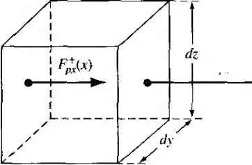 X 4 dx Figure 6.4 I DiUctntidi volume showing x component of the hole-particle flux. -V dx dydz, where V is the divergence of the flux vector. We will hmit ourselves to a one-dimensional analysis. The generation rate and recombination rate of holes will also affect the hole concentration in the differential volume. The net increase in the number of holes per unit time in the differential volume element is then given by bp dF p - dxdydz = -- dxdydz + gpdxdvdz---dxdv dz (6.17) dt 3x Tpt where p is the density of holes. The first term on the right side of Equation (6.17) is the increase in the number of holes per unit time due to the hole flux, the second term is the increase in the number of holes per unit time due to the generation of holes, and the last term is the decrease in the number of holes per unit time due to the recombination of holes. The recombination rate for holes is given by pjXpx where Xp includes the thermal equilibrium carrier lifetime and the excess carrier lifetime. If we divide both sides of Equation (6.17) by the differential volume dx dydz, the net increase in the hole concentration per unit time is dp dF p dt dx Tpt Equation (6.18) is known as the continuity equation for holes. Similarly, the one-dimensional continuity equation for electrons is given by dn dF~ n - = --+g -- (6.19) at dx Tftt where F is the electron-particle flow, or flux, also given in units of number of electrons/cm -s. 6.2.2 Time-Dependent Diffusion Equations In Chapter 5, we derived the hole and electron current densities, which are given, in one dimension, by Jp = efXppE -E>p- (6.20) Л = ер. пЕ -h e£> - (6.21) If we divide the hole current density by (-e) and the electron current density by (-e), we obtain each particle flux. These equations become = PppE -Dp (6.22) Jtj bn F- = -n nE-D - (6.23) i-e) dx Taking the divergence of Equations (6.22) and (6.23), and substituting back into the continuity equations of (6.18) and (6.19), we obtain э7 = - + э; + - - dn д(пЕ) Ъ^п n -- = +M - + o + -- (6.25) at dx dx Tnt Keeping in mind that we are limiting ourselves to a one-dimensional analysis, we can expand the derivative of the product as d(pE) dp dE -=E-hp- (6.26) dx dx dx In a more generalized three-dimensional analysis, Equation (6.26) would have to be replaced by a vector identity. Equations (6.24) and (6.25) can be written in the form dp ( dp dE\ p dp dn ( dn 6E\ n dn Equations (6.27) and (6.28) are the time-dependent diffusion equations for holes and electrons, respectively. Since both the hole concentration p and the electron concentration n contain the excess concentrations. Equations (6.27) and (6.28) describe the space and time behavior of the excess carriers. The hole and electron concentrations are functions of both the thermal equilibrium and the excess values are given in Equations (6.5a) and (6.5b). The thermal-equilibrium concentrations, n and po, are not functions of time. For the special case of a homogeneous semiconductor, о and po are also independent of the space coordinates. Equations (6.27) and (6.28) may then be written in the form dHSn) /d(Sn) BE\ n d{Sn) д, + Ц^+п-и, - - = (6.30) Note that the Equations (6.29) and (6.30) contain terms involving the total concentrations, p and rt, and terms involving only the excess concentrations, 8p and 5rt. 6.3 I AMBIPOLAR TRANSPORT Originally, we assumed that the electric field in the current Equations (6.20) and (6.21) was an applied electric field. This electric field term appears in the time-dependent diffusion equations given by Equations (6.29) and (6.30). If a pulse of
Figure 6,5 I The creation of an internal electric field as excess electrons and holes tend to separate. excess electrons and a pulse of excess holes are created at a particular point in a semiconductor with an applied electric field, the excess holes and electrons will tend to drift in opposite directions. However, because the electrons and holes are charged particles, any separation will induce an internal electric field between the two sets of particles. This internal electric field will create a force attracting the electrons and holes back toward each other. This effect is shown in Figure 6.5. The electric field term in Equations (6.29) and (6.30) is then composed of the externally applied field plus the induced internal field. This E-field may be written as (6-31) where Ецрр is the applied electric field and Ei t is the induced internal electric field. Since the internal E-field creates a force attracting the electrons and holes, this E-field will hold the pulses of excess electrons and excess holes together. The negatively charged electrons and positively charged holes then will drift or diffuse together with a single effective mobility or diffusion coefficient. This phenomenon is called ambipolar diffusion or ambipolar transport. 6.3,1 Derivation of the Ambipolar Transport Equation The time-dependent diffusion Equations (6.29) and (6.30) describe the behavior of the excess carriers. However, a third equation is required to relate the excess electron and hole concentrations to the internal electric field. This relation is Poissons equation, which may be written as e{bp - Sn) t)E (6.32) where c is the permittivity of the semiconductor material. To make the solution of Equations (6.29), (6.30), and (6.32) more tractable, we need to make some approximations. We can show that only a relatively small internal electric field is sufficient to keep the excess electrons and holes drifting and diffusing together. Hence, we can assume that E, (6.33) However, the V term may not be negligible. We will impose the condition of charge neutrality: We will assume that the excess electron concentration is just balanced by an equal excess hole concentration at any point in space and time. If this assumption were exactly true, there would be no induced internal electric field to keep the two sets of particles together. However, only a very small difference in the excess electron concentration and excess hole concentration will set up an internal E-field sufficient to keep the particles diffusing and drifting together. We can show that a 1 percent difference inSp and for example, will result in non-negligible values of the V E = V Ejnt term in Equations (6.29) and (6.30). We can combine Equations (6.29) and (6.30) to eliminate the V E term. Considering Equations (6.1) and (6.4), we can define gn gpg (6.34) and considering Equations (6.2) and (6.6), we can define 4> (6.35) The lifetimes in Equation (6.35) include the thermal-equilibrium carrier lifetimes and the excess-carrier Иfetimes. If we impose the charge neutrafity condition, then Sn 8p, We will denote both the excess electron and excess hole concentrations in Equations (6.29) and (6.30) by Sn.Wc may then rewrite Equations (6.29) and (6.30) as d(Sn) { a(5n) ЭЕ + g-R = d(8n) дЧВп) , /Шп) + g-R d{Sn) dt (6.36) (6.37) If we multiply Equation (6.36) by multiply Equation (6.37) by p-pp, and add the two equations, the V E = dE/dx term will be eliminated. The result of this addition gives ,d(8n) d(8n) If we divide Equation (6.38) by the term itxn -\- pipp), this equation becomes + (M n + fippHg - R) = (д + fipP) a (5/7) dt (6.38) where 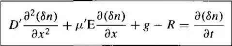 (6.39) pinnPpP 1 ... 17 18 19 20 21 22 23 ... 55 |
|
© 2026 AutoElektrix.ru
Частичное копирование материалов разрешено при условии активной ссылки |