 |
 |
 |
| Главная Журналы Популярное Audi - почему их так назвали? Как появилась марка Bmw? Откуда появился Lexus? Достижения и устремления Mercedes-Benz Первые модели Chevrolet Электромобиль Nissan Leaf |
Главная » Журналы » Simple coaxial reflectometer 1 ... 8 9 10 11 12 13 14 ... 80 HANDBOOK R-C Coupled Amplifiers 111 Cc  Figure 6 STANDARD CIRCUIT FOR RESISTANCE-CAPACITANCE COUPLED PENTODE AM-PLIFIER STAGE assist the designer of such stages, data on operating conditions for commonly used tubes is published in the RCA Tube Handbook RC-16. It is assumed, in the case of the gain equations of figure 5, that the cathode by-pass capacitor, Ck, has a reactance that is low with respect to the cathode resistor at die lowest frequency to be passed by the amplifier stage. R-C Coupled Figure 6 illustrates the stand-Pentode Stages ard circuit for a resistance-capacitance coupled pentode amplifier stage. Cathode bias is used and the screen voltage is supplied through a dropping resistor from the plate voltage supply. In conventional audio-frequency amplifier design such stages are normally used at low voltage levels (from 0.00001 to 0.1 volts peak on the grid of the tube) and use moderate-Gm pentodes such as the 6SJ7. Normal voltage gain for a stage of this type is from 60 to 250, depending upon the tube chosen and its operating conditions. Pentode tubes are ordinarily used the first stage of an R-C amplifier where the high gain which they afford is of greatest advantage and where only a small voltage output is required from the stage. The voltage gain per stage of a resistance-capacitance coupled pentode amplifier can be calculated with the aid of the equivalent circuits and expressions for the mid-frequency, high-frequency, and low-frequency range given in figure 7. To assist the designer of such stages, data on operating conditions for commonly used types of tubes is published in the RCA Tube Handbook RC-16. It is assumed, in the case of the gain equations of figure 7, that the cathode by-pass capacitor, C, has a reactance that is low with respect to the cathode resistor at the lowest frequency to be passed by the stage. It is additionally assumed that the reactance of the screen by-pass capacitor Cj, is low with respect to the screen dropping resistor, Rj, at the lowest frequency to be passed by the amplifier stage. Cascade Voltage When voltage amplifier stages Amplifier Stages are operated in such a manner that the ouфut voltage of the first is fed to the grid of the second, and so forth, such stages are said to be cascaded. The total voltage gain of cascaded amplifier Figure 7 Equivalent circuits and gain equations for a pentode R-C coupled amplifier stage. In using these equations be sure /0 select the values of and Rp wbicb ore proper for the static currents and voltages with which the tube will oper-ate. These voiues may be obtained from curves published in the RCA Tube Handbook RC-16. I:-GmEg MID FREQUENCY RANGE 1=-GmEg
HIGH FREQUENCY RANGE  LOW FREQUENCY RANGE A = Gm Req Reo = RcRp A high freq. 1 A mio freq. 1+(Req/Xs)2 Req = 1 , -Вк+Ru + Rc Rp L ZTTr CCpk+Cgk (dvnamic) A low fbeq. , A mio freq. 1+Cxc/R): Xc = R= Rg + 27ГгСс Rl Rp Rl+ Rp < о ), RL= 500 000 ohms 2.Rl= 100ооо ohms 3. Rl= 50 ооо ohms 4. Rl= 20000 ohms  1000 10000 100000 FREQUENCY fc.P.S ) lOoAo Figure 8 The variation of stage gain with frequency in an r-c coupled pentode amplifier for vari-ous values of plate load resistance stages is obtained by talcing the product of the voltage gains of each of the successive stages. Sometimes the voltage gain of an amplifier stage is rated in decibels. Voltage gain is converted into decibels gain through the use of the following expression: db = 20 logjo A, where A is the voltage gain of the stage. The total gain of cascaded voltage amplifier stages can be obtained by adding the number of decibels gain in each of the cascaded stages. R-C Amplifier A typical frequency response Response curve for an R-C coupled audio amplifier is shown in figure 8. It is seen that the amplification is poor for the extreme high and low frequencies. The reduced gain at the low frequencies is caused by the loss of voltage across the coupling capacitor. In some cases, a low value of coupling capacitor is deliberately chosen to reduce the response of the stage to hum, or to attenuate the lower voice frequencies for communication purposes. For high fidelity work the product of the grid resistor in ohms times the coupling capacitor in microfarads should equal 25,000. (ie.: 500,000 ohms x 0.05 (dd = 25,000). The amplification of high frequencies falls off because of the Miller effect of the subsequent stage, and the shunting effect of residual circuit capacities. Both of these effects may be minimized by the use of a low value of plate load resistor. Grid Leak Bias for High Mu Triodes The correct operating bias for a high-mu triode such as the 6SL7, is fairly critical, and will be found to be highly variable from tube to tube because of minute variations in contact potential within the tube itself. A satisfactory bias method is to use grid leak bias, with a grid resistor of one to ten meg- J. о i -BIAS - О -4r -BIAS mid-frequency uain = GmVi Rl high-frequencv gain = GwVi Zcoupling network С = CoUTVi + Cn 2 +C[jSTBlBUTeD for compromise high frequency equalization. Xll- 0.5 Xc AT fc Rl = Xc at fc where f с = cutoff fsequency of amplifier Ll = peaking inductor for compromise low frequency equalization Rb = Rk (Gmy, Rl) Rb Ce= R Ck Ck = 2s to 50 jjfd n parallel with OOlMiCA Ce = capacitance from above WITH 00 i WiCA IN PARALLEL Figure 9 SIMPLE COMPENSATED VIDEO AMPLIFIER CIRCUIT Resistor R in conjuncfion with coll serves to flatten the high-frequency response of the stage, while and serve to equalize the low-frequency response of this simple video amplifier stage. ohms connected directly between grid and cathode of the tube. The cathode is grounded. Grid current flows at all times, and the effective input resistance is about one-half the resistance value of the grid leak. This circuit is particularly well suited as a high gain amplifier following low output devices, such as crystal microphones, or dynamic microphones. R-C Amplifier A resistance-capacity General Characteristics coupled amplifier can be designed to provide a good frequency response for almost any desired range. For instance, such an amplifier can be built to provide a fairly uniform amplification for frequencies in the audio range of about 100 to 20,000 cycles. Changes in the values of coupling capacitors and load resistors can extend this frequency range to cover the very wide range required for video service. However, extension of the range can only be obtained at the cost of reduced overall amplification. Thus the R-C method of coupling allows good frequency response with minimum distortion, hut low amplification. Phase distortion is less with R-C coupling HANDBOOK Video Frequency Amplifiers 113 than with other types, except direct coupling. The RC amplifier may exhibit tendencies to motorboat or oscillate if it is used with a high impedance plate supply. Video-Frequency Amplifiers A video-frequency amplifier is one which has been designed to pass frequencies from the lower audio range (lower limit perhaps 50 cycles) to the middle r-f range (upper limit perhaps 4 to 6 megacycles). Such amplifiers, in addition to passing such an extremely wide frequency range, must be capable of amplifying this range with a minimum of amplitude, phase, and frequency distortion. Video amplifiers are commonly used in television, pulse conmiunication, and radar work. Tubes used in video amplifiers must have a high ratio of to capacitance if a usable gain per stage is to be obtained. Commonly available tubes which have been designed for or are suitable for use in video amplifiers are: 6AU6, 6AG5, 6AK5, бСВб, 6AC7, 6AG7, and бКб-GT. Since, at the upper frequency limits of a video amplifier the input and output shunting capacitances of the amplifier tubes have rather low values of reactance, low values of coupling resistance along with peaking coils or other special interstage coupling impedances are usually used to flatten out the gain/frequency and hence the phase/ frequency characteristic of the amplifier. Recommended operating conditions along with expressions for calculation of gain and circuit values are given in figure 9- Only a simple two-terminal interstage coupling network is shown in this figure. The performance and gain-per-stage of a video amplifier can be improved by the use of increasingly complex two-terminal interstage coupling networks or through the use of four-terminal coupling networks or filters between successive stages. The reader is referred to Termans Radio Engineers Handbook for design data on such interstage coupling networks. Other Interstage Coupling Methods Figure 10 illustrates, in addition to resistance-capacitance interstage coupling, seven additional methods in which coupling between two successive stages of an audio-frequency amplifier may be accomplished. Although resistance-capacitance coupling is most commonly used, there are certain circuit conditions wherein coupling methods other than resistance capacitance are more effective. Tronsformer Transformer coupling, as illus-Coupling trated in figure lOB, is seldom used at the present time between two successive single-ended stages of an audio amplifier. There are several reasons why resistance coupling is favored over transformer coupling between two successive single-ended stages. These are: (1) a transformer having frequency characteristics comparable with a properly designed R-C stage is very expensive; (2) transformers, unless they are very well shielded, will pick up inductive hum from nearby power and filament transformers; (3) the phase characteristics of step-up interstage transformers are poor, making very difficult the inclusion of a transformer of this type within a feedback loop; and (4) transformers are heavy. However, there is one circuit application where a step-up interstage transformer is of considerable assistance to the designer; this is the case where it is desired to obtain a large amount of voltage to excite the grid of a cathode follower or of a high-power Class A amplifier from a tube operating at a moderate plate voltage. Under these conditions it is possible to obtain apeak voltage on the secondary of the transformer of a value somewhat greater than the d-c plate supply voltage of the tube supplying the primary of the transformer. Push-PuM Transformer Push-pull transformer Irtterstage Coupling coupling between two stages is illustrated in figure IOC. This interstage coupling arrangement is fairly commonly used. The system is particularly effective when it is desired, as in the system just described, to obtain a fairly high voltage to excite the grids of a high-power audio stage. The arrangement is also very good when it is desired to apply feedback to the grids of the push-pull stage by applying the feedback voltage to the low-potential sides of the two push-pull secondaries. Impedance Impedance coupling between two Coupling stages is shown in figure lOD. This circuit arrangement is seldom used, but it offers one strong advantage over R-C interstage coupling. This advantage is the fact that, since the operating voltage on the tube with the impedance in the plate circuit is the plate supply voltage, it is possible to obtain approitimatcly twice the peak voltage ouфut that it is possible to obtain with R-C coupling. This is because, as has been   о о о О о  (а) resistance-capacitance coupling (в) TRANSFORMER COUPLING  (с) PUSH-PULL TRANSFORMER COUPLING
© IMPEDANCE COUPLING  (D IMPEDANCE-TRANSFORMER COUPLING (F) RESISTANCE-TRANSFORMER COUPLING  1 Л (g) CATHODE COUPLING @ DIRECT COUPLING гАЛЛ(- Figure 10 INTERSTAGE COUPLING METHODS FOR AUDIO FREQUENCY VOLTAGE AMPLIFIERS mentioned before, the d-c plate voltage on an R-C stage is approximately one-half the plate supply voltage. Impedance-Transformer and Resistance-Transformer Coupling These two circuit arrangements, illustrated in figures lOE and lOF, are employed when it is desired to use transformer coupling for the reasons cited above, but where it is desired that the d-c plate current of the amplifier stage be isolated from the primary of the coupling transformer. With most types of high-permeability wide-response transformers it is necessary that there be no direct-current flow through the windings of the transformer. The impedance-transformer arrangement of figure 10E will give a higher voltage output from the stage but is not often used since the plate coupling impedance (choke) must have very high inductance and very low distributed capacitance in order not to restrict the range of HANDBOOK Phase Inverters Gm = - Gm 2G-H rp- яр^ G + 1 g= RkGm 0 +1Г Rk = CATHODE RESISTOR Gm = Gm OF EACH TUBE JU = JU OF EACH TUBE Rp = RpOF EACH TUBE EQUIVALENT FACTORS INDICATED ABOVE BY t) ARE THOSE OBTAINED BV USING AN AMPLIFIER WITH A PAIR OF SIMILAR TUBE TYPES IN CfRCUIT SHOWN ABOVE. Figure 11 Equivalent factors for a pair of similar triodes operating as a cathode-coupled audiofrequency voltage amplifier. the transformer which it and its associated tube feed. The resistance-transformer arrangement of figure lOF is ordinarily quite satisfactory where it is desired to feed a transformer from a voltage amplifier stage with no d.c.in the transformer primary. Cathode The cathode coupling arrangement Coupling of figure lOG has been widely used only comparatively recently. One outstanding characteristic of such a circuit is that there is no phase reversal between the grid and the plate circuit. All other common types of interstage coupling are accompanied by a 180° phase reversal between the grid circuit and the plate circuit of the tube. Figure 11 gives the expressions for determining the appropriate factors for an equivalent triode obtained through the use of a pair of similar triodes connected in the cathode-coupled circuit shown. With these equivalent triode factors it is possible to use the expressions shown in figure 5 to determine the gain of the stage at different frequencies. The input capacitance of such a stage is less than that of one of the triodes, the effective grid-to-plate capacitance is very much less (it is so much less that such a stage may be used as an r-f amplifier without neutralization), and the output capacitance is approximately equal to the grid-to-piate capacitance of one of the triode sections. This circuit is particularly effective with tubes such as the 6J6, 6N7, and 6SN7-GT which have two similar triodes in one envelope. An appropriate value of cathode resistor to use for such a stage is the value which would be used for the cathode resistor of a conventional amplifier using one of the same type tubes with the values of plate voltage and load resistance to be used for the cathode-coupled stage. Inspection of the equations in figure 11 shows that as the cathode resistor is made smaller, to approach zero, the Gm approaches zero, the plate resistance approaches the Rp of one tube, and the mu approaches Zero. As the cathode resistor is made very large the Gm approaches one half that of a single tube of the same type, the plate resistance approaches twice that of one tube, and the mu approaches the same value as one tube. But since the Gm of each tube decreases as the cathode resistor is made larger (since the plate current will decrease on each tube) the optimum value of cathode resistor will be found to be in the vicinity of the value mentioned in the previous paragraph. Direct Coupling Direct coupling between successive amplifier stages (plate of first stage connected directly to the grid of the succeeding stage) is complicated by the fact that the grid of an amplifier stage must be operated at an average negative potential with respect to the cathode of that stage. However, if the cathode of the second amplifier stage can be operated at a potential more positive than the plate of the preceding stage by the amount of the grid bias on the second amplifier stage, this direct connection between the plate of one stage and the grid of the succeeding stage can be used. Figure lOH illustrates an application of this principle in the coupling of a pentode amplifier stage to the grid of a hot-cathode phase inverter. In this arrangement the values of cathode, screen, and plate resistor in the pentode stage are chosen such that the plate of the pentode is at approximately 0. 3 times the plate supply potential. The succeeding phase-inverter stage then operates with conventional values of cathode and plate resistor (same value of resistance) in its normal manner. This type of phase inverter is described in more detail in the section to follow. Phase Inverters It is necessary in order to excite the grids of a push-pull stage that voltages equal in amplitude and opposite in polarity be applied to the two grids. These voltages may be obtained through the use of a push-pull input transformer such as is shown in figure lOC. It is possible also, without the attendant bulk and expense of a push-pull input transformer, to obtain voltages of the pioper polarity and phase through the use of a so-called phase-inverter stage. There are a large number of phase inversion circuits which have heen developed and applied but the three shown in figure 12 have been found over a period of time to be the most satisfactory from the point of view of the number of components required and from the standpoint of the accuracy with which the two out-of-phase voltages are held to the same amplitude with changes in supply voltage and changes in tubes- AH of these vacuum tube phase inverters are based upon the fact that a 180° phase shift occurs within a vacuum tube between the grid input voltage and the plate output voltage. In certain circuits, the fact that the grid input voltage and the voltage appearing across the cathode bias resistor are in phase is used for phase inversion purposes. Hot-Cathode Figure 12A illustrates the hot-Phase Inverter cathode type of phase inverter. This type of phase inverter is the simplest of the three types since it requires only one tube and a minimum of circuit components. It is particularly simple when directly coupled from the plate of a pentode amplifier stage as shown in figure ЮН. The circuit does, however, possess the following two disadvantages: (1) the cathode of the tube must run at a potential of approximately 0.3 times the plate supply voltage above the heater when a grounded common heater winding is used for this tube as well as the other heater-cathode tubes in a receiver or amplifier: (2) the circuit actually has a loss in voltage from its input to either of the output grids - about 0.9 times the input voltage will be applied to each of these grids. This does represent a voltage gain of about 1.8 in total voltage output with respect to input (grid-to-grid output voltage) but it is still small with respect to the other two phase inverter circuits shown. Recommended component values for use with a 6J5 tube in this circuit are shown in figure 12A. If it is desired to use another tube in this circuit, appropriate values for the operation of that tube as a conventional amplifier can be obtained from manufacturers tube data. The value of R obtained should be divided by two, and this new value of resistance placed in the circuit as Rl- The value of from tube manual tables should then be used as Rltl in this circuit, and then the total of Ri and Ri;2 should be equal to Rl- Floating Parophose An alternate type of Phase Inverter phase inverter some- times called the floating paraphase is illustrated in figure 12B. This circuit is quite often used with a 6N7 Cc .02 Rki 1200 >Rk2 ; :27 к Cc .02 sRg 5220 К о h в 300 v. ® HOT CATHODE PHASE INVERTER 6N7  lOJUFD +b300 v. I FLOATING PARAPHASePHAS£ INVERTER  +вЭООУ. © CATHODE COUPLED PHASE INVERTER Figure 12 THREE POPULAR PHASE-INVERTER CIRCUITS WITH RECOMMENDED VALUES FOR CIRCUIT COMPONENTS tube, and appropriate values for the 6N7 tube in this application are shown. The circuit shown with the values given will give a voltage gain of approximately 21 from the input grid to each of the grids of the succeeding stage. It is capable of approximately 70 volts peak output to each grid. The circuit inherently has a small unbalance in output voltage. This unbalance can be eliminated, if it is required for some special application, by making the resistor Rg a few per cent lower in resistance value than Rg3. Cathode-Coupled The circuit shown in figure Phase Inverter 12C gives approximately one-half the voltage gain from the input grid to either of the grids of the succeeding stage that would be obtained from a single tube of the same type operating as a conventional R-C amplifier stage. Thus, with a 6SN7-GT tube as shown (two 6j5s in one HANDBOOK Vacuum Tube Voltmeter 117 01 Ri Rs (-WV-f-Wt-1 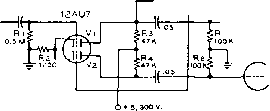 D.c. INPUT SRPi Figure 14 DIRECT COUPLED D-C AMPLIFIER =-Ep Figure 13 VOLTAGE DIVIDER PHASE INVERTER same amplitude as the output of Vi, but of opposite phase. envelope) the voltage gain from the input grid to either of the output grids will be approximately 7 - the gain is, of course, 14 from the input to both output grids. The phase characteristics are such that the circuit is commonly used in deriving push-pull deflection voltage for a cathode-ray tube from a signal ended input signal. The first half of the 6SN7 is used as an amplifier to increase the amplitude of the applied signal to the desired level. The second half of the 6SN7 is used as an inverter and amplifier to produce a signal of the same amplitude but of opposite polarity. Since the common cathode resistor, R, is not by-passed the voltage across it is the algebraic sum of the two plate currents and has the same shape and polarity as the voltage applied to the input grid of the first half of the 6SN7. When a signal, e, is applied to the input circuit, the effective grid-cathode voltage of the first section is Ae/2, when A is the gain of the first section. Since the grid of the second section of the 6SN7 is grounded, the effect of the signal voltage across (equal to e/2 if Rk is the proper value) is the same as though a signal of the same amplitude but of opposite polarity were applied to the grid. The output of the second section is equal to - Ae/2 if the plate load resistors are the same for both tube sections. D-C Amplifiers Voltage Divider Phase Inverter A commonly used phase inverter is shown in figure 13. The input section (VJ is connected as a conventional amplifier. The output voltage from is impressed on the voltage divider Rj-Rg. The values of R; and Rg are in such a ratio that the voltage impressed Upon the grid of Yj is 1/Л times the output voltage of Vi, where A is the amplification factor of Vi. The ouфut of Vj is then of the Direct current amplifiers are special types used where amplification of very slow variations in voltage, or of d-c voltages is desired. A simple d-c amplifier consists of a single tube with a grid resistor across the input terminals, and the load in the plate circuit. Basic D-C A simple d-c amplifier Amplifier Circuit circuit is shown in figure 14, wherein the the grid of one tube is connected directly to the plate of the preceding tube in such a manner that voltage changes on the grid of the first tube will be amplified by the system. The voltage drop across the plate coupling resistor is impressed directly upon the grid of the second tube, which is provided with enough negative grid bias to balance out the excessive voltage drop across the coupling resistor. The grid of the second tube is thus maintained in a slightly negative position. The d-c amplifier will provide good low frequency response, with negligible phase distortion. High frequency response is limited by the shunting effect of the tube capacitances, as in the normal resistance coupled amplifier. A common fault with d-c amplifiers of all types is static instability. Small changes in the filament, plate, or grid voltages cannot be distinguished from the exciting voltage. Regulated power supplies and special balancing circuits have been devised to reduce the effects of supply variations on these amplifiers. A successful system is to apply the plate potential in phase to two tubes, and to apply the exciting signal to a push-pull grid  liiUHil Figure 15 LOFTIN-WHtTE D-C AMPLIFIER  Figure 16 PUSH-PULL D-C AMPLIFIER WITH EITHER SINGLE-ENDED OR PUSH-PULL INPUT circuit configuration. If the two tubes are identical, any change in electrode voltage is balanced out. The use of negative feedback can also greatly reduce drift problems. The Loftin-White Circuit Two d-c amplifier stages may be arranged, so that their plate supplies are effectively in series, as illustrated in figure 15- This is known as a Loftin-White amplifier. All plate and grid voltages may be obtained from one master power supply instead of separate grid and plate supplies. A push-pull version of this amplifier (figure 16) can be used to balance out the effects of slow variations in the supply voltage. 6-10 Single-ended Triode Amplifiers Figure 17 illustrates five circuits for the operation of Class A triode amplifier stages. Since the cathode current of a triode Class Ai (no grid current) amplifier stage is constant with and without excitation, it is common practice to operate the tube with cathode bias. Recommended operating conditions in regard to plate voltage, grid bias, and load impedance for conventional triode amplifier stages are given in the RCA Tube Manual, RC-16. Extended Class A It is possible, under certain Operation conditions to operate single- ended triode amplifier stages (and pentode and tetrode stages as well) with grid excitation of sufficient amplitude that grid current is taken by the tube on peaks. This type of operation is called Class Aj and is characterized by increased pJate-circuit efficiency over straight Class A amplification without grid current. The normal Class A amplifier power stage will operate with a plate circuit efficiency of from 20 percent to perhaps 35 per cent. Through the use of Class Aj Iteration it is possible to increase this plate circuit efficiency to approximately 38 to 45 per cent. However, such operation requires careful choice of the value of plate load impedance, a grid bias supply with good regulation (since the tube draws grid current on peaks although the plate current does not change with signal), and a driver tube with moderate power capability to excite the grid of the Class Aj tube. Figures 17D and 17E illustrate two methods of connection for such stages. Tubes such as the 845, 849, and 304TL are suitable for such a stage. In each case the grid bias is approximately the same as would be used for a Class Al amplifier using the same tube, and as mentioned before, fixed bias must be used along with an audio driver of good regulation - preferably a triode stage with a 1:1 or step-down driver transformer. In each case it will be found that the correct value of plate load impedance will be increased about 40 per cent over the value recommended by the tube manufacturer for Class Al operation of the tube. Operation Choracter- A Class A power amplifier istics of a Triode Operates in such a way as Power Amplifier to amplify as faithfully as possible the waveform applied to the grid of the tube. Large power output is of more importance than high voltage amplification, consequently gain characteristics may be sacrificed in power tube design to obtain more important power handling capabilities. Class A power tubes, such as the 45, 2A3 and 6AS7 are characterized by a low amplification factor, high plate dissipation and relatively high filament emission. The operating characteristics of a Class A HANDBOOK Triode Amplifier Characteristics 119  о о о i 1 @ IMPEDANCE COUPLING  d) TRANSFORMER COUPLING  © IMPEDANCE-TRANSFORMER COUPLING О О ZpiO О о о OZsi о о ZP20 о о о о oZsz Rl о о -bias= +в @ TRANSFORMER COUPLING FOR Аг OPERATION  ® CLASS Аг MODULATOR WITH AUTO-TRANS-FORMER COUPLING Figure 17 Output coupling arrangamonts for single-ended Class A triode audio-frequency power amplifiers. triode amplifier employing an output transformer-coupled load may be calculated from the plate family of curves for the particular tube in question by employing the following steps: 1- The load resistance should be approximately twice the plate resistance of the tube for maximum undistorted power output. Remember this fact for a quick check on calculatioas. 2- Calculate the zero-signal bias voltage (Eg). -(0. 68 X Ebb) Where Е^ь is the actual plate voltage of the Class A stage, and [i is the amplification factor of the tube. 3- Locate the Eg bias point on the Ip vs. Ep graph where the Eg bias line crosses the plate voltage line, as shown in figure 18. Call this point P. 4- Locate on the plate family of curves the value of zero-signal plate current, Ip, corresponding to the operating point, P. 5- Locate 2 x Ip (twice the value of Ip) on the plate current axis (Y-axis). This point corresponds to the value of maximum signal plate current, imax- 6- Locate point x on the d-c bias curve at zero volts (Eg = 0), corresponding to the value of iajt. 7- Draw a straight Iine(x - y) through points X and P. This line is the load resistance line. Its slope corresponds to the value of the load resistance. 8- Load Resistance, (in ohms) max min 11ЛЯУ t where e is in volts, i is in amperes, and Rl is in ohms. 9- Check: Multiply the zero-signal plate current, Ip, by the operating plate voltage, Ep. If the plate dissipation rating of the tube is exceeded, it is necessary to increase the bias (Eg) on the tube so that the plate dissipation falls within the maximum rating of the tube. If this step is taken, operations 2 through 8 must be repeated with the new value of 10- For maximum power output, the peak a-c grid voltage on the tube should swing to 2Eg on the negative cycle, and to zero-bias on the positive cycle. At the peak of the negative swing, the plate voltage reaches e j and the plate current drops to iniin- On the positive swing of the grid signal, the plate voltage drops to Cmin and the plate current reaches imax- The power output of the tube is: Power Output (watts) (max ~ min) (max ~ mln) where i is in amperes and e is in volts. 11- The second harmonic distortion generated in a single-ended Class A triode amplifier, expressed as a percentage of the fundamental output signal is:  100 --, emin. plate volts Em*x. average plate characteristics - 2a3 P.-A-.Z Rp= 800 ohms plate dissipation = 15 watts LOAD RESISTANCE Rl - f ohms 1 max. ~ Lmin. POWER OUTPUT SECOND HARMONIC DISTORTION (Imax.+ Imim.) 2 Imax. ~ Imin, X 100 PERCENT Figure 18 Formulas for determining the operating conditions for a Class A triode single-ended audiofrequency power output stage. A typical load line has been drawn on the average plate char-acterlstics of a type 2A3 tube to illustrate the procedure.  Figure 19 Normal single-ended pentode or beam tetrode audio-frequency power output stage. plifier Stage. Tubes of this type have largely replaced triodes in the output stage of receivers and amplifiers due to the higher plate efficiency (30%-40%) with which they operate. Tetrode and pentode tubes do, however, introduce a considerably greater amount of harmonic distortion in their output circuit, particularly odd harmonics. In addition, their plate circuit impedance (which acts in an amplifier to damp loudspeaker overshoot and ringing, and acts in a driver stage to provide good regulation) is many times higher than that of an equivalent triode. The application of negative feedback acts both to reduce distortion and to reduce the effective plate circuit impedance of these tubes. Operating Choracter- The operating characteristics of a Pentode istics of pentode power Power Amplifier amplifiers may be obtained from the plate family of curves, much as in the manner applied to triode tubes. A typical family of pentode plate curves is shown in figure 20. It can be seen from these curves that the plate current of the tube is relatively independent of the applied plate voltage, but is sensitive to screen voltage. In general, the correct pentode load resistance is about % 2d harmonic = (imax ~~ imin) (X 100) 6-11 Figure 18 illustrates the above steps as applied to a single Class A 2A3 amplifier stage. Single-ended Pentode Amplifiers Figure 19 illustrates the conventional circuit for a single-ended tetrode or pentode am- 0. 9 Ep and the power output is somewhat less than Ep X Ip These formulae may be used for a quick check on more precise calculations. To obtain the operating parameters for Class A pentode amplifiers, the following steps are taken; 1- The imax poiut is chosen so as to fall on the zero-bias curve, just above the knee of the curve (point A, figure 20). 2- A preliminary operating point, P, is determined by the intersection of the plate voltage line, Ep, and the line of ioiax/2. 1 ... 8 9 10 11 12 13 14 ... 80 |
|||||||||||||||||||||||||||||||||
|
© 2026 AutoElektrix.ru
Частичное копирование материалов разрешено при условии активной ссылки |