 |
 |
 |
| Главная Журналы Популярное Audi - почему их так назвали? Как появилась марка Bmw? Откуда появился Lexus? Достижения и устремления Mercedes-Benz Первые модели Chevrolet Электромобиль Nissan Leaf |
Главная » Журналы » Simple coaxial reflectometer 1 ... 9 10 11 12 13 14 15 ... 80 HANDBOOK Push-Pull Amplifiers 121  EpCSTATIC VALUE) вМАХ PLATE volts Figure 20 GRAPHIC DETERMINATION OF OPERATING CHARACTERISTICS OF A PENTODE POWER AMPLIFIER V IS fhe negotive control grid voltage at the operating point P 6- The power output is: Power Ouфut (watts) (imax -imin) + 1-41 dx -ly) X ° = - Where I, is the plate current at the point on the load line where the grid voltage, eg, is equal to: Eg -0.7 Eg; and where ly is the plate current at the point where eg is equal to: Eg + 0. 7 Eg. 7- The percentage harmonic distortion is: % 2d harmonic distortion - imin - 2 Ir - In + 1.41(1,-1J X 100 Where Ip is the static plate current of of the tube. % 3d harmonic distortion imax - imin 1-41 (Ix - ly) imax - imin + 1-41 (Ix - ly) X 100 The grid voltage curve that this point falls upon should be one that is about У2 the value of Eg required to cut the plate current to a very low value (Point B). Point В represents imin on the plate current axis (y-axis). The line imax/2 should be located half-way between iax and tm in- A trial load line is constructed about point P and point A in such a way that the lengths A-P and P-B are approximately equal. 4- ben the most satisfactory load line has been determined, the load resistance may calculated: Rt =- emax e. tmav If 5- The operating bias (Eg) is the bias at point P. 6-12 Push-Pull Audio Amplifiers A number of advantages are obtained through the use of the push-pull connection of two or four tubes in an audio-frequency power amplifier. Two conventional circuits for the use of triode and tetrode tubes in the push-pull connection are shown in figure 21. The two main advantages of the push-pull circuit arrangement are: (I) the magnetizing effect of the plate currents of the output tubes is cancelled in the windings of the output transformer; (2) even harmonics of the input signal (second and fourth harmonics primarily) generated in the push-pull stage are cancelled when the tubes are balanced. The cancellation of even harmonics generated in the stage allows the tubes to be oper- 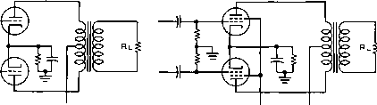 O + e plate PUSH-PULL TRIODE AND TETRODE O+BS.G. O+B PLATE FIGURE 21  100 ISO 200 PLATE VOLTS (Ep) -eo -70 -eo -50 -40 -30 -20 -10 GRID VOLTS (Eg) ® Figure 22 DETERMINATION OF OPERATING PARAMETERS FOR PUSH-PULL CLASS A TRIODE TUBES ated Class AB-in other words the tubes may be operated with bias and input signals of such amplitude that the plate current of alternate tubes may be cut off during a portion of the input voltage cycle. If a tube were operated in such a manner in a single-ended amplifier the second harmonic amplitude generated would be prohibitively high. . Push-pull Class AB operation allows a plate circuit efficiency of from 45 to 60 per cent to be obtained in an amplifier stage depending upon whether or not the exciting voltage is of such amplitude that grid current is drawn by the tubes. If grid current is taken on input voltage peaks the amplifier is said to be operating Class AB2 and the plate circuit efficiency can be as high as the upper value just mentioned. If grid current is not taken by the stage it is said to be operating Class ABi and the plate circuit efficiency will be toward the lower end of the range just quoted. In all Class AB amplifiers the plate current will increase from 40 to 150 per cent over the no-signal value when full signal is applied. The operating characteristics of push-pull Class A amplifiers may also be determined from the plate family of curves for Operating Characteristics of Push-Pull Class A Triode Power Amplifier a particular triode tube by the following steps: 1- Erect a vertical line from the plate voltage axis (x-axis) at 0. 6 Ep (figure 22), which intersects the Eg = 0 curve. This point of intersection (P), interpolated to the plate current axis (y-axis) may be taken as is . It is assumed for simplification that imax occurs at the point of the zero-bias curve corresponding to 0.6 E 2- The power output obtainable from the two tubes is: Power output (Pq) = X Er where Po is expressed in watts, imax in amperes, voltage. and Ep is the applied plate 3- Draw a preliminary load line through point P to the Ep point located on the X-axis (the zero plate current line). This load line represents % of the actual plate-to-plate load of the Class A tubes. Therefore: E 0.6 E Rl (plate-to-plate) = 4 x -~- 1.6 E HANDBOOK Class В Audio Amplifiers 123 where Rl is expressed in ohms, E, volts, and iax in amperes. Figure 22 illustrates the above steps applied to a push-pull Class A amplifier using two 2A3 tubes. 4- The average plate current is 0.636 iax and, multiplied by the plate voltage, Ep, will give the average watts input to the plates of the two tubes. The power output should be subtracted from this value to obtain the total operating plate dissipation of the two tubes. If the plate dissipation is excessive, a slightly higher value of Rl should be chosen to limit the plate dissipation. 5- The correct value of operating bias, and the static plate current for the push-pull tubes may be determined from the Eg vs. Ip curves, wiiich are a derivation of the vs. Ip curves for various values of :.g vs. Ip curve may be constructed 6- The E in this manner: Values of grid bias are read from the intersection of each grid bias curve with the load line. These points are transferred to the Eg vs. Ip graph to produce a curved line, A-B. If the grid bias curves of the Ep vs. Ip graph were straight lines, the lines of the Eg vs. Ip graph would also be straight This is usually not the case. A tangent to this curve is therefore drawn, starting at point A, and intersecting the grid voltage abscissa (x-axis). This intersection (C) is the operating bias point for fixed bias operation. 7- This operating bias point may now be plotted on the original Eg vs. Ip family of curves (C), and the zero-signal current produced by this bias is determined. This operating bias point (C) does not fall on the operating load line, as in the case of a single-ended amplifier. 8- Under conditions of maximum power output, the exciting signal voltage swings from Zero-bias voltage to zero-bias voltage for each of the tubes on each half of the signal cycle. Second harmonic distortion is largely cancelled out. 6-13 Class В Audio Frequency Power Amplifiers The Class Б audio-frequency power amplifier (figure 23) operates at a higher plate-circuit efficiency than any of the previously described types of audio power amplifiers. Full-signal plate-circuit efficiencies of 60 to о о о о о о б В-1- DRIVER о - BIAS feROUND FOR ZERO StAS OPERATING. CONDITION) О о о о В+ MOD. Figure 23 CLASS В AUDIO FREQUENCY POWER AMPLIFIER 70 per cent are readily obtainable with the tube types at present available for this type of work. Since the plate circuit efficiency is higher, smaller tubes of lower plate dissipation may be used in a Class В power amplifier of a given power оифиг than can be used in any other conventional type of audio amplifier. An additional factor in favor of the Class В audio amplifier is the fact that the power input to the stage is relatively low under no-signal conditions. It is for these reasons that this type of amplifier has largely superseded other types in the generation of audio-frequency levels from perhaps 100 watts on up to levels of approximately 150,000 watts as required for large short-wave broadcast stations. Disodvontoges of There are attendant dis-Closs В Amplifier advantageous features to the Operation operation of a power ampli- fier of this type; but all these disadvantages can be overcome by proper design of the circuits associated with the power amplifier stage. These disadvantages are: (1) The Class В audio amplifier requires driving power in its grid circuit; this disadvantage can be overcome by the use of an oversize power stage preceding the Class В stage with a step-down transformer between the driver stage and the Class-B grids. Degenerative feedback is sometimes employed to reduce the plate impedance of the driver stage and thus to improve the voltage regulation under the varying load presented by the Class В grids. (2) The Class В stage requires a constant value of average grid bias to be supplied in spite of the fact that the grid current on the stage is zero over most of the cycle but rises to values as high as one-third of the peak plate current on the peak of the exciting Voltage cycle. Special regulated bias supplies have been used for this application, or В batteries can be used. However, a number of tubes especially designed for Class В audio amplifiers have been developed which require zero average grid bias for their operation. The SUA, 838, 805, 809, HY-5514, and TZ-40 are examples of this type of tube. All these so-called zero-bias tubes have rated operating conditions up to moderate plate voltages wherein they can be operated without grid bias. As the plate voltage is increased to to their maximum ratings, however, a small amount of grid bias, such as could be obtained from several 4 /-volt С batteries, is required. (3), A Class В audio-frequency power amplifier or modulator requires a source of plate supply voltage having reasonably good regulation. This requirement led to the development of the swinging choke. The swinging choke is essentially a conventional filter choke in which the core air gap has been reduced. This reduction in the air gap allows the choke to have a much greater value of inductance with low current values such as are encountered with no signal or small signal being applied to the Class В stage. With a higher value of current such as would be taken by a Class В stage with full signal applied the inductance of the choke drops to a much lower value. With a swinging choke of this type, having adequate current rating, as the input inductor in the filter system for a rectifier power supply, the regulation will be improved to a point which is normally adequate for a power supply for a Class В amplifier or modulator stage. Colculotion of Operoting The following proce-Conditions of Class В dure can be used for Power Amplifiers the calculation of the operating conditions of Class В power amplifiers when they are to operate into a resistive load such as the type of load presented by a Class С power amplifier. This procedure will be found quite satisfactory for the application of vacuum tubes as Class В modulators when it is desired to operate the tubes under conditions which are not specified in the tube operating characteristics published by the tube manufacturer. The same procedure can be used with equal effectiveness for the calculation of the operating conditions of beam tetrodes as Class AB2 amplifiers or modulators when the resting plate current on the tubes (no signal condition) is less than 25 or 30 per cent of the maximum-signal plate current. 1- With the average plate characteristics of the tube as published by the manufacturer before you, select a point on the Ep = Eg (diode bend) line at about twice the plate current you expect the tubes to kick to under modulation. If beam tetrode tubes are concerned, select a point at about the same amount of plate current mentioned above, just to the right of the region where the 1ь line takes a sharp curve downward. This will be the first trial point, and the plate voltage at the point chosen should be not more than about 20 per cent of the d-c voltage applied to the tubes if good plate-circuit efficiency is desired. 2- Note down the value of ipatg and epb at this point. 3- Subtract the value of ерпш from the d-c plate voltage on the tubes. 4- Substitute the values obtained in the following equations: Po = (Ebb - epmin) pmax = Power output from 2 tubes Plate-to-plate load for 2 tubes Full signal efficiency (Np) 78.5 / ерЧ Ebb / Effects of Speech All the above equations are Clipping true for sine-wave operating conditions of the tubes concerned. However, if a speech clipper is being used in the speech amplifier, or if it is desired to calculate the operating conditions on the basis of the fact that the ratio of peak power to average power in a speech wave is approximately 4-to-l as contrasted to the ratio of 2-to-l in a sine wave - in other words, when non-sinusoidal waves such as plain speech or speech that has passed through a clipper are concerned, we are no longer concerned with average power оифиг of the modulator as far as its capability of modulating a Class-C amplifier is concerned; we are concerned with its peakpower-output capability. Under these conditions we call upon other, more general relationships. The first of these is: It requires a peak power output equal to the Class-C stage input to modulate that input fully. The second one is: The average power output required of the modulator is equal to the shape factor of the modulating wave multiplied by the input to the Class-C stage. The shape factor of undipped speech is approximately 0. 25. The shape factor of a sine wave is 0. 5 The shape factor of a speech wave that HANDBOOK Class В P arameters 125 Figure 24 Typical Class В a-f amplifier load line. The load line has been drawn on the average characteristics of a type 87? tube.  aoD 1200 1600 PLATE VOLTS (Ebb) AVERAGE PLATE CHARACTERISTICS TYPE 81 i AND 811-A has been passed through a clipper-filter arrangement is somewhere between 0. 25 and 0. 9 depending upon the amount of clipping that has taken place. With 15 or 20 db of clipping the shape factor may be as high as the figure of 0. 9 mentioned above. This means that the audio power output of the modulator will be 90% of the input to the Class-C stage. Thus with a kilowatt input we would be putting 900 watts of audio into the Class-C stage for 100 per cent modulation as contrasted to perhaps 250 watts for undipped speech modulation of 100 per cent. Somple Calculation Figure 24 shows a set of for 811A Tubes plate charactetistics for a type 81 lA tube with a load line for Class В operation. Figure 25 lists a sample calculation for determining the proper operating conditions for obtaining approximately 185 watts output from a pair of the tubes with 1000 volts d-c plate potential. Also shown in figure 25 is the method of determining the proper ratio for the modulation transformer to couple between the 811s or SllAs and the anticipated final amplifier which is to operate at 2000 plate volts and 175 ma. plate current. Modulation Tronsformer The method illustrated Calculation in figure25 can be used in general for the determination of the proper transformer ratio to couple between the modulator tube and the amplifier to be modulated. The procedure can be Stated as follows; (1) Determine the proper plate-to-plate load impedance for the modulator tubes either by the use of the type of calcula- tion shown in figure 25, or by reference to the published characteristics on the tubes to be used. (2) Determine the load impedance which will be presented by the Class С amplifier stage to be modulated by dividing the operating plate voltage on that stage by the operating value of plate current in amperes. (3) Divide the Class С load impedance determined in (2) SAMPLE CALCULATION CONDITION: 2 type 811 tubes, Ebb, = IDOO input to final stage, 350 w. peak power output NEEDED= 3so + 61b = 370 w. final amplifier Ebb = 2000 v. final amplifier lb = .175 a. final amplifier Zl = 2000 = 11 лпп n .175 EXAMPLE: chose point on en characteristics just to rightof ЕЬЬ=ЕСС. (МШГ Xf F/S. 9-) ipmax. =.410 a. Ep min. = +100 igmax. =.iooa. Eg max. = +80 PEAK PO = .410 x (lOOO-lOO) = .410 x 900 = 389 w, Rl = 4 x = 8800 a. = 8,5 (l--r)= 78.5 (.9) =70. 5 lb Wo (average with sine wave) = po<eak)-,g Win = -Щ^ = 280 w, lb (maximum with sine wave) = £80 ma WG peak = . 100 x 60 = 6w, driving power = -- = 4 w. TRANSFORMER; = i 29 8800 turns ratio = qr=/ 1.29 =1.14stepup Figure 25 Typical calculation of operating conditions for a Class В a-f power omplifier using a pair of type 87 J or 8I7A fubes. Plate characteristics and load line shown in figure 24. above by the plate-to-plate load impedance for the modulator tubes determined in (1) above. The ratio determined in this way is the secondary-to-primary impedance ratio. (4) Take the square root of this ratio to determine the secondary-to-primary turns ratio. If the turns ratio is greater than one the use of a step-up transformer is required. If the turns ratio as determined in this way is less than one a step-down transformer is called for. If the procedure shown in figure 25 has been used to calculate the operating conditions for the modulator tubes, the transformer ratio calculation can be checked in the following manner: Divide the plate voltage on the modulated amplifier by the total voltage swing on the modulator tubes: 2 (Еьь - Ыа)- This ratio should be quite close numerically to the transformer turns ratio as previously determined. The reason for this condition is that the ratio between the total primary voltage and the d-c plate supply voltage on the modulated stage is equal to the turns ratio of the transformer, since a peak secondary voltage equal to the plate voltage on the modulated stage is required to modulate this stage 100 per cent. Use of Clipper Speech When a clipper speech Amplifier with Tetrode amplifier is used in Modulator Tubes conjunction with a Class В modulator stage, the plate current on that stage will kick to a higher value with modulation (due to the greater average power оифиг and input) but the plate dissipation on the tubes will ordinarily be less than with sine-wave modulation. However, when tetrode tubes are used as modulators, the screen dissipation will be much greater than with sine-wave modulation. Care must be taken to insure that the screen dissipation rating on the modulator tubes is not exceeded under full modulation conditions with a clipper speech amplifier. The screen dissipation is equal to screen voltage times screen current. Practicol Aspects of As stated previously, a Class В Modulators Class В audio amplifier requires the driving stage to supply well-regulated audio power to the grid circuit of the Class В stage. Since the performance of a Class В modulator may easily be impaired by an improperly designed driver stage, it is well to study the problems incurred in the design of the driver stage. The grid circuit of a Class В modulator may be compared to a variable resistance which decreases in value as the exciting grid voltage is increased. This variable resistance appears across the secondary terminals of the driver transformer so that the driver stage is called upon to deliver power to a varying load, For best operation of the Class В stage, the grid excitation voltage should not drop as the power taken by the grid circuit increases. These opposing conditions call for a high order of voltage regulation in the driver stage plate circuit. In order to enhance the voltage regulation of this circuit, the driver tubes must have low plate resistance, the driver transformer must have as large a step-down ratio as possible, and the d-c resistance of both primary and secondary windings of the driver transformer should be low. The driver transformer should reflect into the plate circuit of the driver tubes a load of such value that the required driving power is just developed with full excitation applied to the driver grid circuit. If this is done, the driver transformer will have as high a step-down ratio as is consistent with the maximum drive requirements of the Class В stage. If the step-down ratio of the driver transformer is too large, the driver plate load will be so high that the power required to drive the Class В stage to full оифи1 cannot be developed. If the step-down ratio is too small the regulation of the driver stage will be impaired. Driver Stage The parameters for the driver Calculations stage may be calculated from the plate characteristic curve, a sample of which is shown in figure 24. The required positive grid voltage (Cg.ax) for the 811A tubes used in the sample calculation is found at point X, the intersection of the load line and the peak plate current as found on the y-axis. This is + 80 volts. If a vertical line is dropped from point X to intersect the dotted grid current curves, it will be found that the grid current for a single 811A at this value of grid voltage is 100 milliamperes (point Y). The peak grid driving power is therefore 80 X 0.100 = 8 watts. The approximate average driving power is 4 watts. This is an approximate figure because the grid impedance is not constant over the entire audio cycle. A pair of 2A3 tubes will be used as drivers, operating Class A, with the maximum excitation to the drivers occuring just below the point of grid current flow in the 2A3 tubes. The driver plate voltage is 300 volts, and the grid bias is -62 volts. The peak power developed in the primary winding of the driver transformer is: Peak Power (Pp) - 2Rl ( (watts) Rp +Rl where /x is the amplification factor of the driver tubes (4.2 for 2A3). Eg is the peak grid swing of the driver stage (62 volts). Rp is the HANDBOOK Cathode Follower Amplifier 127 plate resistance of one driver tube (800 ohms), Rl is Уг the plate-to-plate load of the driver stage, and Pp is 8 watts. Solving the above equation for Rl, we obtain a value of 14,500 ohms load, plate-to-plate for the 2A3 driver tubes. The peak primary voltage is: epri = 2Rl X Rp +Rl = 493 volts former may result if the plate load impedance of the modulator stage is too low. When the modulator load impedance is too high, the maximum power capability of the stage is reduced. An attempt to increase the output by increasing grid excitation to the stage will result in peak-clipping of the audio wave. In addition, high peak voltages may be built up in the plate circuit that may damage the modulation transformer. and the turns ratio of the driver transformer (primary to У2 secondary) is: 6-14 Cathode-Follower Power Amplifiers eg (max) 80 = 6.15:1 Plote Circuit One of the commonest causes of Impedance distortion in a Class В modu-Matching lator is incorrect load impedance in the plate circuit. The рифозе of the Class В modulation transformer is to take the power developed by the modulator (which has a certain operating impedance) and transform it to the operating impedance imposed by the modulated amplifier stage. If the transformer in question has the same number of turns on the primary winding as it has on the secondary winding, the turns ratio is 1:1, and the impedance ratio is also 1:1. If a 10, ООО ohm resistor is placed across the secondary terminals of the transformer, a reflected load of 10, ООО ohms would appear across the primary terminals. If the resistor is changed to one of 2376 ohms, the reflected primary impedance would also be 2376 ohms. If the transformer has twice as many turns on the secondary as on the primary, the turns ratio is 2:1- The impedance ratio is the square of the turns ratio, or 4:1. If a 10,000 ohm resistor is now placed across the secondary winding, a reflected load of 2,500 ohms will appear across the primary winding. Effects of Plate It can be seen from the Circuit IMis-match above paragraphs that the Class В modulator plate load is entirely dependent upon the load placed upon the secondary terminals of the Class В modulation transformer. If the secondary load is incorrect, certain changes will take place in the operation of the Class В modulator stage. When the modulator load impedance is too low, the efficiency of the Class В stage is reduced and the plate dissipation of the tubes is increased. Peak plate current of the modulator stage is increased, and saturation of the modulation transformer core may result. Talk-back of the modulation trans- The cathode-follower is essentially a power output stage in which the exciting signal is applied between grid and ground. The plate is maintained at ground potential with respect to input and output signals, and the output signal is taken between cathode and ground. Types of Cathode- Figure 26 illustrates four Follower Amplifiers types of cathode-follower power amplifiers in common usage and figure 27 shows the output impedance (Rq), and stage gain (A) of both triode and pentode (or tetrode) cathode-follower stages. It will be seen by inspection of the equations that the stage voltage gain is always less than one, that the output impedance of the stage is much less than the same stage operated as a conventional cathode-return amplifier. The output impedance for conventional tubes will be somewhere between 100 and 1000 ohms, depending primarily on the transconductance of the tube. This reduction in gain and output impedance for the cathode-follower comes about since the stage operates as though it has 100 per cent degenerative feedback applied between its output and input circuit. Even though the voltage gain of the stage is reduced to a value less than one by the action of the degenerative feedback, the power gain of the stage (if it is operating Class A) is not reduced. Although more voltage is required to excite a cathode-follower amplifier than appears across the load circuit, since the cathode follows along with the grid, the relative grid-to-cathode voltage is essentially the same as in a conventional amplifier. Use of Cathode- Although the cathode-fol-Fellower Amplifiers lower gives no voltage gain, it is an effective power amplifier where it is desired to feed a low-impedance load, or where it is desired to feed a load of varying impedance with a signal having good regulation. This latter capability о о о о о о о о о+в ® о о о triode; JicF = JU + I RoCCATHOOE) = PENTODE; p, DCCATH00E1 = A = Gm ReQ A = RlCjU+ 1 j + Rp I + Rl g ® i о О о о о  о о о о о о  Figure 26 CATHODE-FOLLOWER OUTPUT CIRCUITS FOR AUDIO OR VIDEO AMPLIFIERS makes the cathode follower particularly effective as a driver for the grids of a Class В modulator stage. The circuit of figure 26A is the type of amplifier, either single-ended or push-pull, which may be used as a driver for a Class В modulator or which may be used for other applications such as feeding a loudspeaker wliere unusually good damping of the speaker is desired. If the d-c resistance of the primary of the transformer T2is approximately the correct value for the cathode bias resistor for the am- Figure 27 EtfulvaUnf factors for pentode (or tetrode) cathode-follower power amplifiers. plifier tube, the components and need not be used. Figure 2бВ shows an arrangement which may be used to feed directly a value of load impedance which is equal to or higher than the cathode impedance of the amplifier tube. The value of C must be quite high, somewhat higher than would be used in a conventional circuit, if the frequency response of the circuit when operating into a low-impedance load is to be preserved. Figures 26c and 26D show cathode-follower circuits for use with tetrode or pentode tubes. Figure 26C is a circuit similar to that shown in 2бА and essentially the same comments apply in regard to the components R and Ct and the primary resistance of the transformer T2. Notice also that the screen of the tube is maintained at the same signal potential as the cathode by means of coupling capacitor C. This capacitance should be large enough so that at the lowest frequency it is desired to pass dirough the stage its reactance will be low with respect to the dynamic screen-to-cathode resistance in parallel with Rj Tj in this stage as well as in the circuit of figure 26A should have the proper turns (or impedance) ratio to give the desired step-down or step-up from the cathode circuit to the load. Figure 26D is an arrangement frequently used in video systems for feeding a coaxial cable of relatively low inedance from a vacuum-tube amplifier, A pentode or tetrode tube with a cathode impedence as a cathode follower (l/Gm) approximately the same as the cable impedance should be chosen. The 6AG7 and 6AC7 have cathode impedances of the same order as the surge impedances of certain types of low-capacitance coaxial cable. An arrangement such as 26D is also usable for feeding coaxial cable with audio or r-f energy where it is desired to transmit the output signal over moderate distances. The resistor R is added to the circuit as shown if the cathode impedance of the tube used is lower than the HANDBOOK Feedback Amplifiers 129 characteristic impedance of the cable. If the output impedance of the stage is higher than the cable impedance a resistance of appropriate value is sometimes placed in parallel with the input end of the cable. The values of Cj and should be chosen with the same considerations in mind as mentioned in the discussion of the circuit of figure 26C above. The Cothode-Follower The cathode follower in R-F Stoges may conveniently be used as a method of coupling r-f or i-f energy between two units separated a considerable distance. In such an application a coaxial cable should be used to carry the r-f or i-f energy. One such application would be for carrying the оифш of a v-f-o to a transmitter located a considerable distance from the operating position. Another application would be where it is desired to feed a single-sideband demodulator, an FM adaptor, or another accessory with intermediate frequency signal from a communications receiver. A tube such as a бСВб connected in a manner such as is shown in figure 26D would be adequate for the i-f amplifier coupler, while a 6L6 or a 6AG7 could be used in the output stage of a v-f-o as a cathode follower to feed the coaxial line which carries the v-f-o signal from the control unit to the transmitter proper. 6-15 Feedback Amplifiers It is possible to modify the characteristics of an amplifier by feeding back a portion of the output to the input. All components, circuits and tubes included between the point where the feedback is taken off and the point where the feedback energy is inserted are said to be included within the feedback loop. An amplifier containing a feedback loop is said to be a feedback amplifier. One stage or any number of stages may be included within the feedback loop. However, the difficulty of obtaining proper operation of a feedback amplifier increases with the bandwidth of the amplifier, and with the number of stages and circuit elements included within the feedback loop. Gain and Phase-shift The gain and phase in Feedback Amplifiers shift of any amplifier are functions of frequency. For any amplifier containing a feedback loop to be completely stable the gain of such an amplifier, as measured from the input back to the point where the feedback circuit connects to the input, must be less than one
VOLTAGE AMPLIFICATION WITH FEEDBACK 1-Afl A = GAIN IN ABSENCE OF FEEDBACK В = FRACTION OF OUTPUT voltage FED BACK a IS NEGATIVE FOR NEGATIVE FEEDBACK fEEOBACK IN DECIBELS = 20 LOG (1 -AS) MID FREQ. GAIN WITHOUT FEEDBACK = 20 LOG DISTORTION WITH FEEDBACK = MIDFREQ. GAIN WITH FEEDBACK DISTORTION WITHOUT FEEDBACK (-AS) WHERE = 1-AS Rq = OUTPUT IMPEDANCE OF AMPLIFIER WITH FEEDBACK Rn = 0UTPUT IMPEDANCE OF AMPLIFIER WITHOUT FEEDBACK Rl = LOAD IMPEDANCE INTO WHICH AMPLIFIER OPERATES Figure 28 FEEDBACK AMPLIFIER RELATIONSHIPS at the frequency where the feedback voltage is in phase with the input voltage of the amplifier. If the gain is equal to or more than one at the frequency where the feedback voltage is in phase with the input the amplifier will oscillate. This fact imposes a limitation upon the amount of feedback which may be employed in an amplifier which is to remain stable. If the reader is desirous of designing amplifiers in which a large amount of feedback is to be employed he is referred to a book on the subject by H. W. Bode-* Types of Feedback may be either negative Feedback or positive, and the feedback voltage may be proportional either to output voltage or output current. The most commonly used type of feedback with a-f or video amplifiers is negative feedback proportional to output voltage. Figure 28 gives the general operating conditions for feedback amplifiers. Note that the reduction in distortion is proportional to the reduction in gain of the amplifier, also that the reduction in the output impedance of the amplifier is somewhat greater than the reduction in the gain by an amount which is a function of the ratio of the H. W. Bode, Network AnolysIs and Feedback Amplifier Design, D. Von Nostrand Co., 250 Fourtii Ave., New York 3, N. Y- Rz Vz  De feedback = zo l0& R; + Ra (Gmvz Ho ] Rj + RA(vOLTAG£bAmOFVzi1 gain of both stages where- Rb = GmVj Ro ro - reflected load impeoance on vz r2= FEEDBACK resistor (USUAL Lr ABOuT bOO К ) output impedance [Ri + RaCGmvz Ro)]x 0+-ЦИ ) Rn = plate impedance of V2 Figure 29 SHUNT FEEDBACK CIRCUIT FOR PENTODES OR TETRODES This circuit requires onfy the addif/on of one resistor, Rj, to the normal circuit for such an application. The plate Impedance and distortion Introduced by the output stage are materially reduced. output impedance of the amplifier without feedback to the load impedance. The reduction in noise and hum in those stages included within the feedback loop is proportional to the reduction in gain. However, due to the reduction in gain of the output section of the amplifier somewhat increased gain is required of the stages preceding the stages included within the feedback loop. Therefore the noise and hum output of the entire amplifier may or may not be reduced dependent upon the relative contributions of the first part and the latter part of the amplifier to hum and noise. If most of the noise and hum is coming from the stages included within the feedback loop the undesired signals will be reduced in the output from the complete amplifier. It is most frequently true in conventional amplifiers that the hum and distortion come from the latter stages, hence these will be reduced by feedback, but thermal agitation and microphonic noise come from the first stage and will not be reduced but may be increased by feedback unless the feedback loop includes the first stage of the amplifier. Figure 29 illustrates a very simple and effective application of negative voltage feedback to an output pentode or tetrode amplifier stage. The reduction in hum and distortion may amount to 15 to 20 db. The reduction in the effective plate impedance of the stage will be by a factor of 20 to 100 dependent upon the operating conditions. The circuit is commonly used in commercial equipment with tubes such as the 6SJ7 for Vi and the 6V6 or 6L6 for Vj. 6-16 Vacuum-Tube Voltmeters The vacuum-ttibe volttneler may be considered to be a vacuum-tube detector in which the rectified d-c current is used as an indication of the magnitude of the applied alternating voltage. The vacuum tube voltmeter (v.t.v.m.) consumes little or no power and it may be calibrated at 60 cycles and used at audio or radio frequencies with little change in the calibration. Basic D-C Vacuum Tube Voltmeter A simple v.t.v.m. is shown in figure 30. The plate load may be a mechanical device, such as a relay or a meter, or the output voltage may be developed across a resistor and used for various control purposes. The tube is biased by Ec and a fixed value of plate current flows, causing a fixed voltage drop across the plate load resistor, Rp. When a positive d-c voltage is applied to the input terminals it cancels part of the negative grid bias, making the grid more positive with respect to the cathode. This grid voltage change permits a greater amount of plate current to flow, and develops a greater voltage drop across the plate load resistor. A negative input voltage would decrease the plate current and decrease the voltage drop across Rp. The varying voltage drop across Rp may be employed as a control voltage for relays or other devices. When it is desired to measure various voltages, a voltage D.c. INPUT Rp =METER COIL Figure 30 SIMPLE VACUUM TUBE VOLTMETER 1 ... 9 10 11 12 13 14 15 ... 80 |
|||||||||||||||
|
© 2026 AutoElektrix.ru
Частичное копирование материалов разрешено при условии активной ссылки |