 |
 |
 |
| Главная Журналы Популярное Audi - почему их так назвали? Как появилась марка Bmw? Откуда появился Lexus? Достижения и устремления Mercedes-Benz Первые модели Chevrolet Электромобиль Nissan Leaf |
Главная » Журналы » Simple coaxial reflectometer 1 ... 11 12 13 14 15 16 17 ... 80 HANDBOOK High Fidelity Amplifier 141 FEEDBACK RESISTOR Figure 18 TYPICAL TRIODE AMPLIFIER WITH FEEDBACK LOOP. 6SJ7 i- 470 К 600< ;=0.1 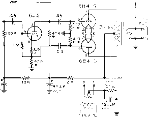 AT 125 MA * = MATCHED PAIR RESISTORS varying load of two to nearly one hundred ohms to the output stage (figure 17). It is necessary to employ a high quality output transformer to match the loudspeaker load to the relatively high impedance plate circuit of the power amplifier stage. In general, push-pull amplifiers are employed for the output stage since they have even harmonic cancelling properties and permit better low frequency response of the output transformer since there is no d-c core saturation effect present. To further reduce the harmonic distortion and intermodulation inherent in the amplifier system a negative feedback loop is placed around one or more stages of the unit. Frequency response is thereby improved, and the output impedance of the amplifier is sharply reduced, providing a very low source impedance for the loudspeaker. Shown in figure 18 is a basic push-pull triode amplifier, using inverse feedback around the power output and driver stage. A simple triode inverter is used to provide 180-degree phase reversal to drive the grid circuit of the power amplifier stage. Maximum undistorted power output of this amplifier is about 8 watts. A modification of the basic triode amplifier is the popular Williamson circuit (figure 19) developed in England in 1947. This circuit rapidly became the standard of comparison in a few short years. Pentode power tubes are connected as triodes for the output stage, and negative feedback is taken from the secondary of the output transformer to the cathode of the input stage. Only the most linear portion of the tube characteristic curve is used. Although that portion has been extended by higher than normal plate supply voltage, it FEEDBACK RESISTOR 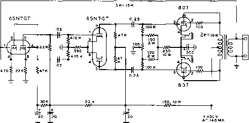 Figure 19 U. S. VERSION OF BRITISH WILLIAMSON AMPLIFIER PROVIDES 10 WATTS POWER OUTPUT AT LESS THAN 2% INTERMODULATION DISTORTION. 6SN7 STAGE USES DIRECT COUPLING. 807/5881 TO FEEDBACK CIRCUIT 0.2.5 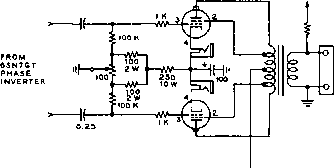 OUTPUT 807/5881 NOTE ! P/ CONNECTIONS AHE FOR e07 TUBES + 400 V. Figure 20 ULTRA-LINEAR CONFIGURATION OF WILLIAMSON AMPLIFIER DOUBLES POWER OUT-PUT, AND REDUCES IM LEVEL. SCREEN TAPS ON OUTPUT TRANSFORMER PERMIT SEMI-TETRODE OPERATION. is only a fraction of the curve normally used in amplifiers. Thus a comparatively low output power level is obtained with tubes capable of much more efficient operation under less stringent requirements. With 400 volts applied to the output stage, a power output of 10 watts may be obained wtih less than 2% intermodulation distortion. A recent variation of the Williamson circuit involves the use of a tapped output transformer. The screen grids of the push-pull amplifier stage are connected to the primary taps, allowing operating efficiency to approach that of the true pentode. Power output in excess of 25 watts at less than 2% intermodulation dis-     Sip р|(рШ Э111Шм11яЯ Figure 21 BABY HI-FI AMPLIFIER IS DWARFED BY 12-INCH SPEAKER ENCLOSURE This miniature music system is capable of excellent perforrrtanee in the small home or apartment. Preamplifier, bass and treble controls, and volume corttrol are all incorporated in the unit. Amplifier provides 4 waits output at 4% /А4 distortion. tortion may be obtained with this circuit (figure 20). 7-4 Amplifier ConsfrucHon Wiring Assembly and layout of high Techniques fidelity audio amplifiers follows the general technique described for other forms of electronic equipment. Extra care, however, must be taken to insure that the hum level of the amplifier is extremely low. A good hi-fi system has excellent response in the 60 cycle region, and even a minute quantity of induced a-c voltage will be disagreeably audible in the loudspeaker. Spurious eddy currents produced in the chassis by the power transformer are usually responsible for input stage hum. To insure the lowest hum level, the power transformer should be of the upright type instead of the half-shell type which can couple minute voltages from the windings to a steel chassis. In addition, part of the windings of the half-shell type project below the chassis where they are exposed to the input wiring of the amplifier. The core of the power transformer should be placed at right angles to the core of a nearby audio transformer to reduce spurious coupling between the two units to a minimum. It is common practice in amplifier design to employ a ground bus return system for all audio tubes. All grounds are returned to a single heavy bus wire, which in turn is grounded at one point to the metal chassis. This ground point is usually at the input jack of the amplifier. When this system is used, a-c chassis currents are not coupled into the amplifying stages. This type of construction is illustrated in the amplifiers described later in this chapter. HANDBOOK Amplifier Construction 143 PHONO INPUT {HIGH LEVEL) I2AU7 .05 220 -LJ ijM з  BASE TREBLE CONTROL CONTROL 56 к > 12AU7 VOLUME CONTROL 450 V. 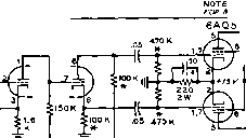 : Rl =8.2 K\-l + 12K 1 W -mov. 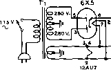 3K 2W -I-m- Zp=io W-Rl 10K 6AQ5 о SPKR NOTES 1. RESISTORS 0.5 WATT UNLESS OTHERWISE SPECIFI60 a. ALL CAPACITOR VAL V€S IN MP UNLESS OTHERWISE SPECIFIED 3. RESISTORS MARKED ARE MATCHED PAIRS 12AUT AAQS 4 SAQ5 Figure 22 SCHEMATIC, BABY HI-FI AMPLIFIER Г,-260-0-260 volts of 90 ma., 6.3 vo/ts at 4.0 CH,-1.5 henry at 200 ma. Chicago Standard C-2327, amp., upright mounting. Chicago-Standard CA-B-C-30-20-10 p-fd. 350 volt. Mallory fp-330.7 PC-8420. Tt-70 K, CT. to 8, 16 ohms. Peerless (Altec) NOTE-Feedback loop returns to 8 ohm tap on Тг S-S10F. when 8 ohm speaker is used. Care should be taken to reduce the capacitance to the chassis of high impedance circuits, or the high frequency response of the unit will suffer. Shielded bath-tub type capacitors should not be used for interstage coupling capacitors. Tubular paper capacitors are satisfactory. These should be spaced well away from the chassis. It is a poor idea to employ the chassis as a common filament return, especially for low level audio stages. The filament center-tap of the power transformer should be grounded, and twisted filament wires run to each tube socket. High impedance audio components and wiring should be kept clear of the filament lines, which may even be shielded in the vicinity of the input stage. In some instances, the filament center tap may be taken from the arm of a low resistance, wirewound potentiometer placed across the filament pins of the input tube socket. The arm of this potentiometer is grounded, and the setting of the control is adjusted for minimum speaker hum. 7-5 The Baby Hi Fi A definite need exists for a compact, high fidelity audio amplifier suitable for use in the small home or apartment. Listening tests have shown that an average power level of less than one watt in a high efficiency speaker will provide a comfortable listening level for a small room, and levels in excess of two or three watts are uncomfortably loud to the ear. The Baby Hi-Fi amplifier has been designed for use in the small home, and will provide excellent quality at a level high enough to rattle the windows. Designed around the new Elearo-Voice miniature ceramic cartridge, the amplifier will provide over 4 watts power, measured at the secondary of the output transformer. At this level, the distortion figure is below 1%, and the IM figure is A%. At normal listening levels, the IM is much lower, as shown in figure 24. The Amplifier The schematic of the ampli-Circuit fier is shown in figure 22. Bass and treble boost controls are incorporated in the circuit, as is the volume control. A dual purpose 12AU7 double triode serves as a voltage amplifier with cathode degeneration. A simple voltage divider network is used in the grid circuit to prevent amplifier overloading when the ceramic cartridge is used. The required input signal for maximum output is of the order of О.З volts. The output level of the Electro-Voice cartridge is approximately twice this, as shown in figure 7. The use of the high-level cartridge elimin- 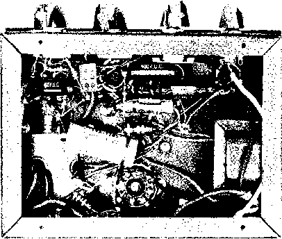 Figure 23 UNDER-CHASSIS VIEW OF BABY HI-FI Low level audio stages are at upper left, with components mounted between socket pins and potentiometer controls. 6X5 socket is at lower center at photo with filter choke CHi at right. Feedback resistor Ri is at left of rectifier socket. ates the necessity of high gain amplifiers required when low level magnetic pickup heads are used. Problems of hum and distortion introduced by these extra stages are thereby eliminated, greatly simplifying the amplifier. The second section of the 12AU7 is used for bass and treble boost. Simple R-C networks are placed in the grid circuit permitting gain boost of over 12 db at the extremities of the response range of the amplifier. A second 12AU7 is employed as a direct coupled hot-cathode phase inverter, capaci-tively coupled to two 6AQ5 pentode connected z g I-< Э о cc z
0 1 г Э 4 5 EQUIVALENT SINE WAVE WATTS Figure 24 INTERMODULATION CURVE FOR BABY HI-FI AS MEASURED ON HEATHKIT INTERMODULATION ANALYZER. output tubes. The feedback loop is run from the secondary of the output transformer to the cathode of the input section of the phase inverter. The power supply of the Baby Hi-Fi consists of a 6X5-GT rectifier and a capacitor input filter. A second R-C filter section is used to smooth the d-c voltage applied to the 12AU7 tubes. A cathode-type rectifier is used in preference to the usual filament type to prevent voltage surges during the warm-up period of the other cathode-type tubes. Amplifier The complete amplifier is Construction built upon a small amplifier foundation chassis and cover measuring 5 x7 x6 (Bud CA-1754). Height of the ampUfier including dust cover is 6 . The power transformer (Ti) and output transformer (Та) are placed in the rear corners of the chassis, with the*6X5-GT rectifier socket placed between them. The small filter choke (CHi) is mounted to the wall of the chassis and may be seen in the under-chassis photograph of figure 23- The four audio tubes are placed in a row across the front of the chassis. Viewed from the front, the 12AU7 tubes are to the left, and the 6AQ5 tubes are to the right. The three section filter capacitor (CiA, B, C) is a chassis mounting unit, and is placed between the rectifier tube and the four audio tubes. Since the chassis is painted, it is important that good grounding points be made at each tube socket. The paint is cleared away HANDBOOK Baby Hi-Fi 145 Figure 25 TYPICAL INTERMODULATION TEST OF AUDIO AMPLIFIER. Audio tones of two frequencies are applied to input of amplifier under test, and amplitude of sum or difference frequency is meosured, providing relative inter-modulation figure. ;J III -V4frt -  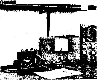 beneath the socket bolt heads, and lock nuts are used beneath the socket retaining nuts to insure a good ground connection. All ground leads of the first 12AU7 tube are returned to the socket, whereas all grounds for the rest of the circuit are returned to a ground lug of filter capacitor Ci. Since the input level to the amplifier is of the order of one-half volt, the problem of chassis ground currents and hum is not so prevalent, as is the case with a high gain input stage. Phonograph-type coaxial receptacles are mounted on the rear apron of the chassis, serving as the input and output connections. The four panel controls (bass boost, treble boost, volume, and a-c on) are spaced equidistant across the front of the chassis. Amplifier The filament wiring should be Wiring done first. The center-tap of the filament winding is grounded to a lug of the 6X5-GT socket ring, and the 6-3 volt leads from the transformer are attached to pins 2 and 7 of the same socket. A twisted pair of wires run from the rectifier socket to the right-hand 6AQ5 socket (figure 23). The filament leads then proceed to the next 6AQ5 socket and then to the two 12AU7 sockets in turn. The 12AU7 preamplifier stage is wired next. A two terminal phenolic tie-point strip is mounted to the rear of the chassis, holding the 12K decoupling resistor and the positive lead of the 10 fiid; 450-volt filter capacitor. All B-plus leads are run to this point. Most of the components of the bass and treble boost system may be mounted between the tube socket terminals and the terminals of the two potentiometers. The feedback resistor Ri is mounted between the terminal of the coaxial output connector and a phenolic tie-point strip placed beneath an adjacent socket bolt. When the wiring has been completed and checked, the amplifier should be turned on, and the various voltages compared with the values given on the schematic. It is important that the polarity of the feedback loop is correct. The easiest way to reverse the feedback polarity 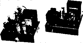 Figure 26 20-WATT WILLIAMSON-TYPE AMPLIFIER PROVIDES ULTIMATE IN LISTENING PLEASURE FOR THE GOLDEN EAR. Amplifier chassis (left) employs two low level stages driving push-pull 807 tubes in so-called Ultra-linear circuit. Power supply is at fight. input (0.75 и RMSMAX.) 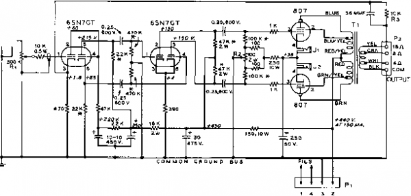 notes: 1- all resistors 1-watt unless otherwise specified 2- resistors marked w are matched pairs 3- voltace measurements made with 1000 ohms/volt voltmeter 4- jacks Jl and j2 are insulated from chassis 5- all capacitor values siven in mfd, unless otherwise noted e- transformer Til STANCOR A-SOTZ, 7s00 ohm primary 7- punched and drilled chassis, SrA A/COR w a Figure 27 SCHEMATIC OF 20-WATT MUSIC SYSTEM AMPLIFIER. is to cross-connect the two plate leads of the 6AQ5 tubes. If the feedback polarization is incorrect, the amplifier will oscillate at a supersonic frequency and the reproduced signal will sound fuzzy to the ear. The correct connection may be determined with the aid of an oscilloscope, as the oscillation will be easily found. The builder might experiment with different values of feedback resistor Rj, especially if a speaker of different impedance is employed. Increasing the value of Ri will decrease the degree of feedback. For an 8-ohm speaker, Ri should be decreased in value to maintain the same amount of feedback. This amplifier was used in conjunction with a General Electric S-1201A 12-inch speaker mounted in an Electro-Voice KD6 Aristocrat speaker enclosure which was constructed from a kit. The reproduction was extremely smooth, with good balance of bass and treble. 7-6 A High Quality 25 Watt Amplifier This amplifier is recommended for the music lover who desires the utmost in high fidelity. Capable of delivering 25 watts output at less than 1.5% intermodulation distortion, the amplifier will provide flawless reproduction at higher than normal listening levels. It is true that other designs have been advocated providing greater power at a lower IM distortion level. However, the improvement in reproduc- tion of such a system is not noticeable - even to the trained ear - over the results obtained with this low priced amplifier. A full 20 watts of audio power are obtained over the frequency range of 20 to 50,000 cycles at less than 0.1% harmonic distortion. At the average listening level of 1 watt, the frequency response is plus or minus 1 decibel at 100,000 cycles, assuring true high fidelity response over the entire audible range. Preamplification and tone compensation are not included in this unit, as these functions are accomplished In the auxiliary driving amplifier. If a variable reluctance cartridge Is employed, the preamplifiers of figure 9 or figure 14 may be used with this unit. The Heathkit WA-P2 preamplifier is also recommended for general use when several input circuits are to be employed. The Amplifier The schematic of this ampli-Circuit fler is shown In figure 27. It is a Williamson-type amplifier using the so-called Ultra-linear screen-tap circuit on the output stage. A dual triode 6SN7-GT serves as a voltage amplifier and direct coupled phase Inverter. Maximum signal input to this stage Is approximately 0-8 volt, r.m.s. for rated output of the amplifier. The feedback loop from the speaker voice coil is returned to the cathode circuit of the input stage, placing all amplifying stages within the loop. A second 6SN7-GT is used as a push-pull Figure 28 UNDER-CHASSIS VIEW OF 20-WATT AMPLIFIER. 807 SOCKETS ARE AT CENTER, WITH CATHODE BALANCING POTENTIOMETER AT LOWER RIGHT. Nota ground bus, starting at center, top filter capacitor, and running in loop around underside of chassis. Bus is grounded to chassis at input plug (upper left). Shielded leads run to volume control (center). 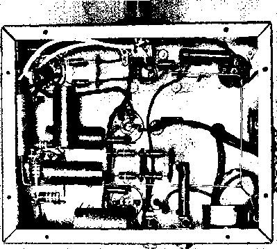 driver stage for the high level output amplifier. A plate potential of 430 volts is applied to this stage to insure ample grid drive to the output stage. Large value coupling capacitors are used between all stages to prevent signal degeneration at the lower audio frequencies. Two 807 beam-power tubes are employed in the final amplifier stage. Cathode bias is applied to these tubes, and the current of the tubes may be equalized by potentiometer Rs in the bias circuit. Degenerative feedback is taken from the secondary of the output transformer and applied to the input of the amplifier. The amount of feedback is controlled by the value of feedback resistor Rs. A small capacitor is placed across Rs to reduce any tendency towards high frequency parasitic oscillation sometimes encountered when long leads are used to connect the amplifier to the loudspeaker. An external power supply is used with the amplifier, delivering 440 volts at a current of 175 milliamperes, and 6.3 volts at 5 amperes. Amplifier The amplifier is bulk upon a ConsfrucHon steel chassis measuring 9 x 7 x2 . Punched and drilled chassis for both the amplifier and power supply may be obtained as standard parts, as specified in figure 27, eliminating the necessity of considerable metal work. Placement of the major components may be seen in the top and under-chassis photographs. The two cathode current jacks, Ji and Ja are mounted in oversize holes and are insulated from the chassis with fibre shoulder washers placed 0П the jack stem, and flat fibre washers beneath the retaining nut. The can-type filter capacitors are in- sulated from the chassis by fibre mounting boards. A common ground bus is used in this amplifier, and all grounds are returned to the bus, rather than to the chassis. The bus is grounded at the input jack of the amplifier and runs around the underside of the chassis, ending at the ground terminals of the high voltage filter capacitors. Tie-point terminal strips are used to support the smaller components, and direct point-to-point wiring is used. Matched pairs of resistors should be used in the balanced audio circuits, and these resistors are marked (* ) on the schematic. If possible, measure a quantity of resistors in the store with an ohmmeter, and pick out the pairs of resistors that are most evenly matched. The exact resistance value is not critical within 10% as long as the two resistors are close in value-Care must be taken when these resistors are soldered in the circuit, as the heat of the soldering iron may cause the resistance value to vary. It is wise to grasp the resistor lead with a long-nose pliers, holding the lead between the point where the iron is applied and the body of the resistor. The pliers will act as a heat sink , protecting the resistor from excessive heat. The filament leads are made up of a twisted pair of wires running between the various sockets. Keep the twisted leads clear of the input jack to insure minimum hum pickup. The plate leads from the 807 caps pass through -inch rubber grommets mounted in the chassis to phenolic tie points mounted beneath the chassis. The plate leads of output transformer Tl attach to these tie points. Be sure you ob- о < :э Q О (Г 0 4 8 12 16 го 24 as 32 EQUIVALENT SINE WAVE WATTS Figure 29 INTERMODULATION CURVE OF 20-WATT AMPLIFIER. serve the color code for these leads, as given in figure 27, as the proper polarization of the leads is required for proper feedback operation. When the amplifier wiring is completed, all connections should be checked for accidental grounds or transpositions. Make sure the meter jacks are insulated from the chassis. The Power A companion power supply for Supply the high fidelity amplifier is shown in figure 30. A cathode-type 5V4-G rectifier is used to limit the warm-up surge voltages usually encountered in such a supply. Filament and plate voltages for the Heathkit WA-P2 preamplifier may be derived from receptacle SO-1. If the preamplifier is not used, or if another type of preamplifier is to be employed, the center-tap of the 6.3 volt filament winding of power transformer Ti (green/yellow lead) should be grounded to the chassis of the power supply. Wiring of this unit is straightforward, and no unusual precautions need be taken. It is v?ise to attach the amplifier to the supply before it is turned to limit warm-up voltage excursions. Amplifier The amplifier is attached to the Operotion power supply by a short length of 4-wire cable. Make sure taht the filament leads (pins 1 and 4, Pj) are made of sufficiently heavy wire to insure that the filaments of the amplifier receive a full 6.3 volts. The amplifier should be turned on and all voltages checked against figure 27. A speaker or suitable resistive load should be attached to output terminal strip Pa, and a 0-100 d-c milliammeter plugged into jacks Ji and Js. Balance potentiometer R2 is now adjusted until the two readings are the same. Each measurement will be very close to 60 milliamperes when the currents are balanced. The amplifier is now ready for operation, and has a fidelity curve similar to that shown in figure 29- 5V4-G 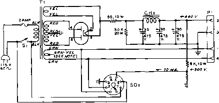 NOTE: IF HEATHKIT PREAMPLIFien SOCKET FOR IS NOT USED, CENTER-TAP WIRE 4* WA-Pt {CREEN-yELLOW) OF e.3 FILAMENT PREAMPLIFIER WINDING OF Ti MUST BE 6R0UN0E0. SDK, 10 W Ti - 400-0-400 VOLTS, 200 MA.. 5 VOLTS. 3 AMP., e.3 VOLTS. 5 AMP. CHICAGO-STANDARD PC-e41Z CH 1 - 4.5 HENRY AT 200 MA. CHICAeO-STANDARO C-I4II Figure 30 POWER SUPPLY FOR 20.WATT AMPLIFIER. CHAPTER EIGHT Radio Frequency Vacuum Tube Amplifiers TUNED RF VACUUM TUBE AMPLIFIERS Tuned r-f voltage amplifiers are used in receivers for the amplification of the incoming r-f signal and for the amplification of intermediate frequency signals after the incoming frequency has been converted to the intermediate frequency by the mixer stage. Signal frequency stages are normally called tuned r-f amplifiers and intermediate-frequency stages are called /-/ amplifiers. Both tuned r-f and i-f amplifiers are operated Class A and normally operate at signal levels from a fraction of a microvolt to amplitudes as high as 10 to 50 volts at the plate of the last i-f stage in a receiver. Grid Circuit Considerations Since the full amplification of a receiver follows the first tuned circuit, the operating conditions existing in that circuit and in its coupling to the antenna on one side and to the grid of the first amplifier stage on the other are of greatest importance in determining the signal-to-noise ratio of the receiver on weak signals. First Tuned It is obvious that the highest Circuit ratio of signal-to-noise be im- pressed on the grid of the first r-f amplifier tube. Attaining the optimum ratio is a complex problem since noise will be generated in the antenna due to its equivalent radiation resistance (this noise is in addition to any noise of atmospheric origin) and in the first tuned circuit due to its equivalent coupled resistance at resonance. The noise voltage generated due to antenna radiation resistance and to equivalent tuned circuit resistance is similar to that generated in a resistor due to thermal agitation and is expressed by the following equation: Miere: = r-m-s value of noise voltage over the interval Af k ~ Boltzmans constant = 1.374 X 10- joule per °K. T = Absolute temperature K. R - Resistive component of impedance across which thermal noise is developed. Af = Frequency band across which voltage is measured. In the above equation Af is essentially the frequency band passed by the intermediate frequency amplifier of the receiver under consideration. This equation can be greatly simplified for the conditions normally encountered in communications work. If we assume the following conditions: T =: 300° К or 27° С or 80.5° F, room temperature; Af = 8000 cycles (the average pass band of a communications receiver or speech amplifier), the equation reduces to: Er.n s. - 0.0115 \JR microvolts. Accordingly, the thermal-agitation voltage appearing in the center of half-wave antenna (assuming effective temperature to be 300° K) having a radiation resistance of 73 ohms is approximately 0.096 microvolts. Also, the thermal agitation voltage appearing across a 500,-000-ohm grid resistor in the first stage of a speech amplifier is approximately 8 microvolts under the conditions cited above. Further, the voltage due to thermal agitation being impressed on the grid of the first r-f stage in a receiver by a first tuned circuit whose resonant resistance is 50,000 ohms is approximately 2.5 microvolts. Suffice to say, however, that the value of thermal agitation voltage appearing across the first tuned circuit when the antenna is properly coupled to this circuit will be very much less than this value. It is common practice to match the impedance of the antenna transmission line to the input impedance of the grid of the first r-f amplifier stage in a receiver. This is the condition of antenna coupling which gives maximum gain in the receiver. However, when u-h-f tubes such as acorns and miniatures are used at frequencies somewhat less than their maximum capabilities, a significant improvement in signal-to-noise ratio can be attained by increasing the coupling between the antenna and first tuned circuit to a value greater than that which gives greatest signal amplitude out of the receiver. In other words, in the 10, 6, and 2 meter bands it is possible to attain somewhat improved signal-to-noise ratio by increasing antenna coupling to the point where the gain of the receiver is slightly reduced. It is always possible, in addition, to obtain improved signal-to-noise ratio in a v-h-f receiver through the use of tubes which have improved input impedance characteristics at the frequency in question over conventional types. Noise Focior The limiting condition for sensitivity in any receiver is the thermal noise generated in the antenna and in the first tuned circuit. However, with proper coupling between the antenna and the grid of the tube, through the first tuned circuit, the noise contribution of the first tuned circuit can be made quite small. Unfortunately, though, the major noise contribution in a properly designed receiver is that of the first tube. The noise contribution due to electron flow and due to losses in the tube can be lumped into an equivalent value of resistance which, if placed in the grid circuit of a perfect tube having the same gain but no noise would give the same noise voltage output in the plate load. The equivalent noise resistance of tubes such as the 6SK7, 6SG7, etc., runs from 50t)0 to 10,000 ohms. Very high Gm tubes such as the 6AC7 and 6AK5 have equivalent noise resistances as low as 700 to 1500 ohms. The lower the value of equivalent noise resistance, the lower will be the noise output under a fixed set of conditions. The equivalent noise resistance of a tube must not be confused with the actual input loading resistance of a tube. For highest signal-to-noise ratio in an amplifier the input loading resistance should be as high as possible so that the amount of voltage that can be developed from grid to ground by the antenna energy will be as high as possible. The equivalent noise resistance should be as low as possible so that the noise generated by this resistance will be lower than that attributable to the antenna and first tuned circuit, and the losses in the first tuned circuit should be as low as possible. The absolute sensitivity of receivers has been designated in recent years in government and commercial work by an arbitrary dimension-less number known as noise factor or N. The noise factor is the ratio of noise ouфut of a perfect receiver having a given amount of gain with a dummy antenna matched to its input, to the noise output of the receiver under measurement having the same amount of gain with the dummy antenna matched to its input. Although a perfect receiver is not a physically realizable thing, the noise factor of a receiver under measurement can be determined by calculation from the amount of additional noise (from a temperature-limited diode or other calibrated noise generator) required to increase the noise power output of a receiver by a predetermined amount. Tube Input As has been mentioned in a pre-Loading vious paragraph, greatest gain in a receiver is obtained when the antenna is matched, through the r-f coupling transformer, to the input resistance of the r-f tube. However, the higher the ratio of tube input resistance to equivalent noise resistance of the tube the higher will be the sig-nai-to-noise ratio of the stage-and of course, the better will be the noise factor of the overall receiver. The input resistance of a tube is very high at frequencies in the broadcast band and gradually decreases as the frequency increases. Tube input resistance on conventional tube types begins to become an important factor at frequencies of about 25 Mc. and above. At frequencies above about 100 Mc. the use of conventional tube types becomes impracticable since the input resistance of the tube has become so much lower than the equivalent noise resistance that it is impossible to attain reasonable signal-to-noise ratio on any but very strong signals. Hence, special v-h-f tube types such as the 6AK5, 6AG5, and 6CB6 must be used. The lowering of the effective input resist- 1 ... 11 12 13 14 15 16 17 ... 80 |
|
© 2026 AutoElektrix.ru
Частичное копирование материалов разрешено при условии активной ссылки |