 |
 |
 |
| Главная Журналы Популярное Audi - почему их так назвали? Как появилась марка Bmw? Откуда появился Lexus? Достижения и устремления Mercedes-Benz Первые модели Chevrolet Электромобиль Nissan Leaf |
Главная » Журналы » Simple coaxial reflectometer 1 ... 12 13 14 15 16 17 18 ... 80 ance of a vacuum tube at higher frequencies is brought about by a number of factors. The first, and most obvious, is the fact that the dielectric loss in the internal insulators, and in the base and press of the tube increases with frequency. The second factor is due to the fact that a finite time is required for an electron to move from the space charge in the vicinity of the cathode, pass between the grid wires, and travel on to the plate. The fact that the electrostatic effect of the grid on the moving electron acts over an appreciable portion of a cycle at these high frequencies causes a current flow in the grid circuit which appears to the input circuit feeding the grid as a resistance. The decrease in input resistance of a tube due to electron transit time varies as the square of the frequency. The undesirable effects of transit time can be reduced in certain cases by the use of higher plate voltages. Transit time varies inversely as the square root of the applied plate voltage. Cathode lead inductance is an additional cause of reduced input resistance at high frequencies. This effect has been reduced in certain tubes such as the 6SH7 and the 6AK5 by providing two cathode leads on the tube base. One cathode lead should be connected to the input circuit of the tube and the other lead should be connected to the by-pass capacitor for the plate return of the tube. The reader is referred to the Radiation Laboratory Series, Volume 23: Microwave Receivers (McGraw-Hill, publishers) for additional information on noise factor and input loading of vacuum tubes. Plote-Circuit Considerations Noise is generated in a vacuum tube by the fact that the current flow within the tube is not a smooth flow but rather is made up of the continuous arrival of particles (electrons) at a very high rate. This shot effect is a source of noise in the tube, but its effect is referred back to the grid circuit of the tube since it is included in the equivalent noise resistance discussed in the preceding paragraphs. Plate Circuit For the purpose of this section, Coupling it will be considered that the function of the plate load circuit of a tuned vacuum-tube amplifier is to deliver energy to the next stage with the greatest efficiency over the required band of frequencies. Figure 1 shows three methods of interstage coupling for tuned r-f voltage amplifiers. In figure lA omega (cS) is 2n times the resonant frequency of the circuit in the plate of 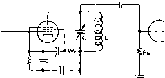 @ AMPLIFICATION AT RESONANCE(APPROX.) =GmU)LQ 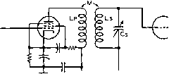 O+b © AMPLIFICATION AT RESONANCE CAPPROX.)=GmOUMQ  О / CP о о о о о о Lp Ls © AMPLIFICATION AT RESONANCEfAPPROHGMК QpQi WHEHEi 1. PHI. AND SEC. RESONANT AT SAME PREQUENCY 2. К IS COEPPICIENT OF COUPLING IF PRI. AND SEC. Q ARE APPROXIMATELY THE SAME. TOTAL BANDWIDTH - . , \t CENTER FREQUENCY MAXIMUM AMPLITUDE OCCURS AT CRITICAL COUPLING-1 WHEN К = /qTqs Figure 1 Goin equations for p e nta de r-f amplifier stages operating into a tuned load the amplifier tube, and L and Q are the inductance and Q of the inductor L. In figure IB the notation is the same and M is the mutual inductance between the primary coil and the secondary coil. In figure 1С the notation is again the same and k is the coefficient of coupling between the two tuned circuits. As the coefficient of coupling between the circuits is increased the bandwidth becomes greater but the response over the band becomes progressively more double-humped. The response over the band is the most flat when the Qs of primary and secondary are approximately the same and the value of each Q is equal to 1.75/4. Variabie-Mu Tubes It is common practice to in R-F Stages control the gain of a suc- cession of r-f or i-f amplifier stages by varying the average bias on their control grids. However, as the bias is raised above the operating value on a conventional sharp-cutoff tube the tube becomes increasingly non-linear in operation as cutoff of plate current is approached. The effect of such non-linearity is to cause cross modulation between strong signals which appear on the grid of the tube. When a tube operating in such a manner is in one of the first stages of a receiver a number of signals are appearing on its grid simultaneously and cross modulation between them will take place. The result of this effect is to produce a large number of spurious signals in the output of the receiver-in most cases these signals will carry the modulation of both the carriers which have been cross modulated to produce the spurious signal. The undesirable effect of cross modulation can be eliminated in most cases and greatly reduced in the balance through the use of a variable-mu tube in all stages which have a-v-c voltage Or other large negative bias applied to their grids. The variable-mu tube has a characteristic which causes the cutoff of plate current to be gradual with an increase in grid bias, and the reduction in plate current is accompanied by a decrease in the effective amplification factor of the tube. Variable-mu tubes ordinarily have somewhat reduced G as compared to a sharp-cutoff tube of the same group. Hence the sharp-cutoff tube will perform best in stages to which a-v-c voltage is not applied. RADIO-FREQUENCY POWER AMPLIFIERS All modern transmitters in the medium-frequency range and an increasing percentage of those in the v-h-f and u-h-f ranges consist of a comparatively low-level soiirce of radio-frequency energy which is multiplied in frequency and successively amplified to the desired power level. Microwave transmitters are still predom-inatelv of the self-excited oscillator type, but when it is possible to use r-f amplifiers in s-h-f transmitters the flexibility of their application will be increased. The following portion of this chapter will be devoted, however, to the method of operation and calculation of operating characteristics of r-f power amplifiers for operation in the range of approximately 3.5 to 500 Mc. Class С R-F Power Amplifiers The majority of r-f power amplifiers fall into the Class С category since such stages can be made to give the best plate circuit efficiency of any present type of vacuum-tube amplifier. Hence, the cost of tubes for such a stage and the cost of the power to supply that stage is least for any given power оифи!. Nevertheless, the Class С amplifier gives less power gain than either a Class A or Class В amplifier under similar conditions since the grid of a Class С stage must be driven highly positive over the portion of the cycle of the exciting wave when the plate voltage on the amplifier is low, and must be at a large negative potential over a large portion of the cycle so that no plate current will flow except when plate voltage is very low. This, in fact, is the fundamental reason why the plate circuit efficiency of a Class С amplifier stage can be made high-plate current is cut off at all times except when the plate-to-cathode voltage drop across the tube is at its lowest value. Class С amplifiers almost invariably operate into a tuned tank circuit as a load, and as a result are used as amplifiers of a single frequency or of a comparatively narrow band of frequencies. Relationships in Figure 2 shows the relation-Closs С Stoge ships between the various voltages and currents over one cycle of the exciting grid voltage for a Class С amplifier stage. The notation given in figure 2 and in the discussion to follow is the same as given at the first of Chapter Six under Symbols for Vacuum-Tube Parameters. The various manufacturers of vacuum tubes publish booklets listing in adequate detail alternative Class С operating conditions for the tubes which they manufacture. In addition, operating condition sheets for any particular type of vacuum tube are available for the asking from the different vacuum-tube manufacturers. It is, nevertheless, often desirable to determine optimum operating conditions for a tube under a particular set of circumstances. To assist in such calculations the following paragraphs are devoted to a method of calculating Class С operating conditions which is moderately simple and yet sufficiently accurate for all practical purposes. HANDBOOK Class С R-F Amplifiers I5J 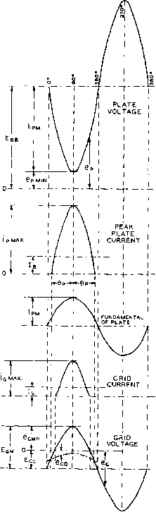 COMPONENT CURRENT Figure 2 /nsfonfoneous electrode artd tank circuit voltages and currents for a Class С r-f power amplifier Calculation of Class С Amplifier Operating Characteristics Although Class С operating conditions can be determined with the aid of the more conven- tional grid voltage-plate current operating curves, the calculation is considerably simplified if the alternative constant-current curve of the tube in question is used. This is true since the operating line of a Class С amplifier is a straight line on a set of constant-current curves. A set of constant-current curves on the 250TH tube with a sample load line drawn thereon is shown in figure 5. In calculating and predicting the operation of a vacuum tube as a Class С radio-frequency amplifier, the considerations which determine the operating conditions are plate efficiency, power output required, maximum allowable plate and grid dissipation, maximum allowable plate voltage and maximum allowable plate current. The values chosen for these factors will depend both upon the demands of a particular application and upon the tube chosen. The plate and grid currents of a Class С amplifier tube are periodic pulses, the durations of which are always less than 180 degrees. For this reason the average grid current, average plate current, power output, driving power, etc., cannot be directly calculated but must be determined by a Fourier analysis from points selected at proper intervals along the line of operation as plotted upon the constant-current characteristics. This may be done either analytically or graphically. While the Fourier analysis has the advantage of accuracy, it also has the disadvantage of being tedious and involved. The approximate analysis which follows has proved to be sufficiently accurate for most applications. This type of analysis also has the advantage of giving the desired information at the first trial. The system is direct in giving the desired information since the important factors, power output, plate efficiency, and plate voltage are arbitrarily selected at the beginning. Method of The first step in the method to Calculation be described is to determine the power which must be delivered by the Class С amplifier. In making this determination it is well to remember that ordinarily from 5 to 10 per cent of the power delivered by the amplifier tube or tubes will be lost in well-designed tank and coupling circuits at frequencies below 20 Mc. Above 20 Mc. the tank and circuit losses are ordinarily somewhat above 10 per cent. The plate power input necessary to produce the desired оифиг is determined by the plate efficiency: Pjn = Pout/Np- For most applications it is desirable to operate at the highest practicable efficiency. High-efficiency operation usually requires less expensive tubes and power supplies, and the о 50 RATIO Figure 3 Relationship between the peak value of the fundamental component of the tube plate car-rent, and average plate current; as compared to the ratio of the instantaneous peak value of tube plate current, and average plate current о 0 < RATIO-SbL Ecc Figure 4 Relationship between the ratio of the peak value af the fundamental component of the grid excitation voltage, and the average grid bias; as compared to the ratio between instantaneous peak grid current and average grid current amount of artificial cooling required is frequently less than for low-efficiency operation. On the other hand, high-efficiency operation usually requires more driving power and involves the use of higher plate voltages and higher peak tube voltages. The better types of triodes will ordinarily operate at a plate efficiency of 75 to 85 per cent at the highest rated plate voltage, and at a plate efficiency of 65 to 75 per cent at intermediare values of plate voltage. The first determining factor in selecting a tube or tubes for a particular application is the amount of plate dissipation which will be requited of the stage. The total plate dissipation rating for the tube or tubes to be used in the stage must be equal to or greater than that calculated from: Pp = Pin - Pout-After selecting a tube or tubes to meet the power ouфut and plate dissipation requirements it becomes necessary to determine from the tube characteristics whether the tube selected is capable of the desired operation and, if so, to determine the driving power, grid bias, and grid dissipation. The complete procedure necessary to determine a set of Class С amplifier operating conditions is given in the following steps: 1. Select the plate voltage, power оифиг, and efficiency. 2. Determine plate input from; Piu -Pout/Np. 3. Determine plate dissipation from: Pp- Pin - Pouf Pp must not exceed maximum rated plate dissipation for tube or tubes selected. 4. Determine average plate current from: lb = Pin/Ebb. 5. Determine approximate ipmax from: ipmax = 4.9 lb for Np =0.85 ipmax - 4-5 lb for Np = 0.80 ipinax = 4.0Ib for Np = 0.75 ipmax = 3.5 lb for Np = 0.70 6. Locate the point on constant-current characteristics where the constant plate current line corresponding to the approximate ipmax determined in step 5 crosses the line of equal plate and grid voltages (diode line). Read epjn at this point. In a few cases the lines of constant plate current will inflect sharply upward before reaching the diode line. In these cases ei should not be read at the diode line hut at the point where the plate current line intersects a line drawn from the origin through these points of inflection. HANDBOOK Constant Current Calculations 1 55 FIRSr TRIAL POINT FINAL POINT 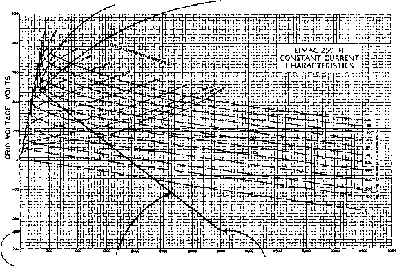 Ej. 240 LOAD LINE PLATE VOLTAGE-VOLTS Ebb= + 3500 FIGURE 5 Active portion of the operating load line for an Eimac 2S0TH Class С r-f power amplifier, showing first trial point and the final operating point 7. Calculate Ep from: Ep = Еьь - epmin- 8. Calculate the ratio Ipm/Jb from: Ipm 2 Np Ebb 9. From the ratio of Ipn,/Ib calculated in step 8 determine the ratio ipmax/lfa ftom figure 3- 10. Calculate a new value for ipax ftom the ratio found in step 9- ipmax = (ratio from step 9) 1ь 11. Read Cgp and igmax from the constant-current characteristics for the values of Cpmin and ipm ax determined in steps 6 and 10. 12. Calculate the cosine of one-half the angle of plate current flow from: 0p = 2.32 .Ipm \ 13. Calculate the grid bias voltage from: 1 cos вг 1 - cos в. Ebb -t - e gmpi for triodes. Ecc = 1 - COS в. - egmp COS 9 - for tetrodes, where /г, is the grid-screen amplification factor, and Ej-j is the d-c screen voltage. 14. Calculate the peak fundamental grid excitation voltage from: Egm - gmp * cc 15. Calculate the ratio Egm/Ecc for the val- ues of and Eg found in steps 13 and 14. 16. Read igmax/lc ftom figure 4 for the ratio Fgm/Ecc found in step 15. 17. Calculate the average grid current from the ratio found in step 16, and the value of igmax found in step 11: 12. cos = 2.32 (1.73 - 1.57) = 0.37 Igm ax Ratio from step 16 18. Calculate approximate grid driving power from: Pd = 0.9 EgIc 19. Calculate grid dissipation from: Pg = Pd + Eclc Pg must not exceed the maximum rated grid dissipation for the tube selected. Sample A typical example of a Class С Colculotion amplifier calculation is shown in the example below. Reference is made to figures 3, 4 and 5 in the calculation. 1. Desired power оифиг-800 watts. 2. Desired plate voltage-3500 volts. Desired plate efficiency-80 per cent (Np = 0.80) Pin = 800/0.80 = 1000 watts 3. Pp = 1000 - 800 = 200 watts Use 250TH; max. Pp = 250w; ц = 37. 4. Ib = 1000/3500 = 0.285 ampere (285 ma.) Max. Ib for 250TH is 350 ma. 5. Approximate ipmax ~ 0.285 X 4.5 = 1.28 ampere 6- epmin = 260 volts (see figure 5 first trial point) 7. Ep = 3500 - 260 = 3240 volts 8. Ip /Ib = 2x0.80X3500/3240 = 5600/3240 = 1.73 9- ipmax/lb = 4.1 (from figure 3) 10. ip a, = 0.285X4.1 = 1.17 11. eg ,p = 240 volts igmax = 0-430 amperes (Both above from final point on figure 5) (брбВ.З ) 13. E = 1 - 0.37 Г / 52 \ 0.37 (-- 240) L \ 37 / = - 240 volts 3500-. 37 - 14. Eg = 240 - (-240) = 480 volts grid swing 15. Eg /Ecc = 480/ - 240 = - 2 16. igmax/Ic 5.75 (from figure 4) 17. Ic = 0.430/5.75 = 0.075 amp. (75 ma. grid current) 18. Pd = 0.9X480X0.075 = 32.5 watts driving power 19. P - 32.5 - (-240X0.75) = 14.5 watts grid dissipation Max. Pg for 250TH is 40 watts The power оифиГ of any type of r-f amplifier is equal to: lpmEpai/2 ~ Pq Ipn, can be determined, of course, from the ratio determined in step 8 above (in this type of calculation) by multiplying this ratio times Ib- It is frequently of importance to know the value of load impedance into which a Class С amplifier operating under a certain set of conditions should operate. This is simply Rl= Fpm/lpm- In the case of the operating conditions just determined for a 250TH amplifier stage the value of load impedance is: R, =. *p m *p m 3240 .495 - 6600 ohms p m X к Q of Amplifier In order to obtain good plate Tank Circuit tank circuit tuning and low radiation of harmonics from an amplifier it is necessary that the plate tank circuit have the correct Q. Charts giving compromise values of Q for Class С amplifiers are given in the chapter. Generation of R-F Energy. However, the amount of inductance required for a specified tank circuit Q under specified operating conditions can be calculated from the following expression: HANDBOOK Class В R-F Amplifiers 157 (o - 2 n X operating frequency L = Tank inductance Rl - Required tube load impedance Q = Effective tank circuit Q A tank circuit Q of 12 to 20 is recommended for all normal conditions. However, if a balanced push-pull amplifier is employed the tank receives two impulses per cycle and the circuit Q may be lowered somewhat from the above values. Quick Method of Colculoting Amplifier Plate Efficiency The plate circuit efficiency of a Class В or Class С r-f amplifier can be determined from the following facts. The plate circuit efficiency of such an amplifier is equal to the product of two factors, F which is equal to the ratio of Epm to Ebb (Fi = Ерп,/Еьь) and Fj, which is proportional to the one-half angle of plate current flow, i9p. A graph of Fj against bodi (9p and cos dp is given in figure 6. Either p or cos вр may be used to determine F,. Cos в may be determined either from the procedure previously given for making Class С amplifier computations or it may be determined from the following expression: cos вр = - Ecc + Ebb Eg -E Example of It is desired to know the one-half Method angle of plate current flow and the plate circuit efficiency for an 812 tube operating under the following conditions which have been assumed from inspection of the data and curves given in the RCA Transmitting Tube Handbook HB-3: 1. Ebb = 1100 volts Ecc - -40 volts (i=29 Egn, = 120 volts Ep = 1000 volts o.ee o.ee o.e. 0.78 o.re 0.70  Ч 20 30 40 50 0 70 80 90 100 И0 120 PP IM electrical DEGREES i i i i i i i i 1.0 0**a O.M O.M* Oe*l 5.W 0M2 0.174 0-00 -o.iT. -o.MZ -o-SOO cos OP Figure 6 Relat!onsh!p between Focfor F2 and the hatf-angle of plate current flow In an amplifier with sine-wave input ond output voltage, operating at a grid-bias voltage greater than cut-off 5. Np= Fi X Fj = 0.91 X 0.79 - 0.72 (72 per cent efficiency) Fi could be called the plate-voltage-swing efficiency factor, and Fj can be called the operating-angle efficiency factor or the maximum possible efficiency of any stage running with that value of half-angle of plate current flow. Np is, of course, only the ratio between power output and power input. If it is desired to determine the power input, exciting power, and grid current of the stage, these can be obtained through the use of steps 7, 8, 9, and 10 of the previously given method for power input and ouфut; and knowing that igmai is 0.095 ampere the grid circuit conditions can be determined through the use of steps 15, 16, 17, 18 and 19. 8-4 Class В Rodio Frequency Power Amplifiers 2- Fi = Ер/Бьь = 0.91 3. cos dp = - 29 X 40 + 1100 29 X 120 - 1000 60 = 0.025 2480 4. Fj = 0.79 (by reference to figure 6) Radio frequency power amplifiers operating under Class В conditions of grid bias and excitation voltage are used in two general types of applications in transmitters. The first general application is as a buffer amplifier stage where it is desired to obtain a high value of power amplification in a particular stage. A particular tube type operated with a given plate voltage will be capable of somewhat greater ouфut for a certain amount of excitation power when operated as a Class В ampli-
CO UJ UJ 0- < ы a. о (Л UJ ol Ш 2 < < J PLATE VOLTS Figure 7 AVERAGE PLATE CHARACTERISTICS OF 813 TUBE fier than when operated as a Class С amplifier. Cqlculotion of Calculation of the operating Operating conditions for this type of Characteristics Class В r-f amplifier can be carried out in a manner similar to that described in the previous paragraphs, except that the grid bias voltage is set on the tube before calculation at the value: Ecc = Ebb/jLt- Since the grid bias is set at cutoff the one-half angle of plate current flow is 90°; hence cos is fixed at 0.00. The plate circuit efficiency for a Class В r-f amplifier operated in this manner can be determined in the following manner: Np-78.5 (-) The Class В The second type of Class В Lineor r-f amplifier is the so-called Class В linear amplifier which is often used in transmitters for the amplification of a single-sideband signal or a conventional amplitude-modulated wave. Calculation of operating conditions may be carried out in a manner similar to that previously described with the following exceptions: The first trial operating point is chosen on the basis of the 100 per cent positive modulation peak of the modulated exciting wave. The piate circuit and grid peak voltages and currents can then be determined and the power input and ouфut calculated. Then, with the exciting voltage reduced to one-half for the no-modulation condition of the exciting wave, and with the same value of load resistance reflected on the tube, the plate input and plate efficiency will drop to approximately one-half the values at the 100 per cent positive modulation peak and the power оифи! of the stage will drop to one-fourth the peak-modulation value. On the negative modulation peak the input, efficiency, and ouфut all drop to zero. In general, the proper plate voltage, bias voltage, load resistance and power output listed in the tube tables for Class В audio work will also apply to Class В linear r-f application. Calculation of Operating Parameters (or a Class В Linear Amplifier Figure 7 illustrates the characteristic curves for an 813 tube. Assume the plate supply to be 2000 volts, and the screen supply to be 400 volts. To determine the operating parameters of this tube as a Class В linear r-f amplifier, the following steps should be taken: 1. The grid bias is chosen so that the resting plate current will produce approximately 1/3 of the maximum plate dissipation of the tube. The maximum dissipation of the 813 is 125 watts, so the bias is set to allow one-third of this value, or 42 watts of resting dissipation. At a plate potential of 2000 volts, a HANDBOOK Linear Amplifier Parameters 159 plate current of 21 milliamperes will produce this figure. Referring to figure 7, a grid bias of -45 volts is approximately correct. 2. A practical Class В linear r-f amplifier runs at an efficiency of about 66% at full output, the efficiency dropping to about 33% with an unmodulated exciting signal. In the case of single-sideband suppressed carrier excitation, a no-excitation condition is substituted for the unmodulated excitation case, and the linear amplifier runs at the resting or quiescent input of 42 watts with no exciting signal. The peak allowable power input to the 813 is: Input Peak Power (Wp) = (watt,s) Plate Dissipation X 100 (100 - % plate efficiency) 125 - X 100 = 379 watts 3. The maximum signal plate current is: pmax Ep 2000 -=0.189 ampere 4. The plate current flow of the linear amplifier is 1809, and the plate current pulses have a peak of 3-14 times the maximum signal current: 3-14 X 0.189 = 0.595 ampere 5. Referring to figure 7, a current of 0.605 ampere (Point A) will flow at a positive grid potential of 60 volts and a minimum plate potential of 420 volts. The grid is biased at 45 volts, so a peak r-f grid voltage of 60 + 45 volts = 105 volts is required. 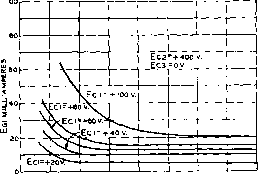 IOO 200 300 PLATE VOLTS Ep Figure 8 Egi VS. Ep CHARACTERISTICS OF 813 TUBE 8. The plate load resistance is: Ep - epmin 1580 Rl -= -= 0.5ipmax 0.5 X -189 = 6000 ohms 9. If a loaded plate tank circuit Q of 12 is desired, the reactance of the plate tank capacitor at the resonant frequency should be: Rl 6000 Reactance (ohms) = ---= 500 ohms Q 12 10. For an operating frequency of 4.0 Mc, the effective resonant capacity is: С = 6.28 X 4.0 X 500 = 80 ififd. 6. The grid driving power required for the Class В linear stage maybe found by the aid of figure 8. It is one-quarter the product of the peak grid current times the peak grid voltage: 0.02 X 10⁵ - 0.53 watt 11. The inductance required to resonate at 4.0 Mc. with this value of capacity is: 6.28 X 4.0 = 19.9 microhenries 7. The single tone power output of the 813 stage is: Pp = 78.5 {Ep - epmin) X Ip Pp-78.5 (2000 - 420)x .189 = 235 watts Grid Circuit 1. The maximum positive grid Considerations potential is 60 volts, and the peak r-f grid voltage is 105 volts. Required driving power is 0.53 watt. The equivalent grid resistance of this stage is: (eg) 2 X P, 2 X 0.53 10,400 ohms 2. As in the case of the Class В audio amplifier the grid resistance of the linear ampUfier varies from infinity to a low value when maximum grid current is drawn. To decrease the effect of this resistance excursion, a swamping resistor should be placed across the grid tank circuit. The value of the resistor should be dropped until a shortage of driving power begins to be noticed. For this example, a resistor of 3,000 ohms is used. The grid circuit load for no grid current is now 3,000 ohms instead of infinity, and drops to 2 400 ohms when maximum grid current is drawn. 3. A circuit Q of 15 is chosen for the grid tank. The capacitive reactance required is: 2400 Xc--- l60 ohms 4. At 4.0 Mc. the effective capachy is: 10 6.28 X 4 X 154 = 248 fd. 5. The inductive reactance required fo resonate the grid circuit at 4.0 Mc. is: = 6.4 microhenries 6.28x4.0 6. By substituting the loaded grid resistance figure in the formula in the first paragraph, the grid driving power is now found to be approximately 2.3 watts. Screen Circuit By reference to the plate Considerations characteristic curve of the 813 tube, it can be seen that at a minimum plate potential of 500 volts, arid a maximum plate current of 0.6 ampere, the screen current will be approximately 30 milliamperes, dropping to one or two milliamperes in the quiescent state. It is necessary to use a well-regulated screen supply to hold the screen voltage at the correct potential over this range of current excursion. The use of an electronic regulated screen supply is recommended. Special R-F Power Amplifier Circuits The r-f power amplifier discussions of Sections 8-4 and 8-5 have been based on the assumption that a conventional grounded-cathode or cathode-return type of amplifier was in question. It is possible, however, as in the case of a-f and low-level r-f amplifiers to use circuits in which electrodes other than the cathode are returned to ground insofar as the signal potential is concerned. Both the plate-return or cathode-follower amplifier and the grid-return or grounded-grid amplifier are effective in certain circuit applications as tuned r-f power amplifiers. Disadvontoges of An undesirable aspect of Grounded-Cotbode the operation of cathode-Amph fiers return r-f power amplifiers using triode tubes is that such amplifiers must be neutralized. Principles and methods of neutralizing r-f power amplifiers are discussed in the chapter Generation of R-F Energy. As the frequency of operation of an amplifier is increased the stage becomes more and more difficult to neutralize due to inductance in the grid and plate leads of the tubes and in the leads to the neutralizing capacitors. In other words the bandwidth of neutralization decreases as the frequency is increased. In addition the very presence of the neutralizing capacitors adds additional undesirable capacitive loading to the grid and plate tank circuits of the tube or tubes. To look at the problem in another way, an amplifier that may be perfectly neutralized at a frequency of 30 Mc. may be completely out of neutralization at a frequency of 120 Mc. Therefore, if there are circuits in both the grid and plate circuits which offer appreciable impedance at this high frequency it is quite possible that the stage may develop a parasitic oscillation in the vicinity of 120 Mc. This condition of restricted-range neutralization of r-f Grounded-Grid R- F Amp! if iers power amplifiers can be greatly alleviated through the use of a cathede- i. return or grounded-grid r-f stage. The grounded-grid amplifier has the following advantages: 1. The output capacitance of a stage is reduced to approximately one-half the value which would be obtained if the same tube or tubes were operated as a conventional neutralized amplifier. 2. The tendency toward parasitic oscillations in such a stage is greatly reduced since the shielding effect of the control grid be- 1 ... 12 13 14 15 16 17 18 ... 80 |
|||||||||||||||||||||||||||||||||||||||||||||||||||||||||||||||||||||||||||||||||||||||||||||||||||||||||||||||||||||||||||||||||||||||||||||||||||||||||||||||||||||||||||||||||||||||||||||||||||||||||||||||||||||||||||||||||||||||||||||||||||||||||||||||||||||||||||||||||||||||||||||||||||||||||||||||||||||||||||||||||||||||||||||||||||||||||||||||||||||||||||||||||||||||||||||||||||||||||||||||||||||||||||||||||||||||||||||||||||||||||||||||||||||||||||||||||||||||||||||||||||||||||||||||||||||||||||||||||||||||||||||||||||||||||||||||||||||||||||||||||||||||||||||||||||||||||||||||||||||||||||||||||||||||||||||||||||||||||||||||||||||||||||||||||||||||||||||||||||||||||||||||||||||||||||||||||||||
|
© 2026 AutoElektrix.ru
Частичное копирование материалов разрешено при условии активной ссылки |