 |
 |
 |
| Главная Журналы Популярное Audi - почему их так назвали? Как появилась марка Bmw? Откуда появился Lexus? Достижения и устремления Mercedes-Benz Первые модели Chevrolet Электромобиль Nissan Leaf |
Главная » Журналы » Simple coaxial reflectometer 1 ... 13 14 15 16 17 18 19 ... 80 tween the filament and the plate is effective over a broad range of frequencies. 3- The feedback capacitance within the stage is the plate-to-cathode capacitance which is ordinarily very much less than the grid-to-plate capacitance. Hence neutralization is ordinarily not required. If neutralization is required the neutralizing capacitors are very small in value and are cross connected between plates and cathodes in a push-pull stage, or between the opposite end of a split plate tank and the cathode in a single-ended stage. The disadvantages of a grounded-grid amplifier are: 1. A large amount of excitation energy is required. However, only the normal amount of energy is lost in the grid circuit of the amplifier tube; all additional energy over this amount is delivered to the load circuit as useful output. 2. The cathode of a grounded-grid amplifier stage is hot to r.f. This means that the cathode must be fed through a suitable impedance from the filament supply, or the secondary of the filament transformer must be of the low-capacitance type and adequately insulated for the r-f voltage which will be present. 3. A grounded-grid r-f amplifier cannot be plate modulated 100 per cent unless the output of the exciting stage is modulated also. Approximately 70 per cent modulation of the exciter stage as the final stage is being modulated 100 per cent is recommended. However, the grounded-gtrd r-f amplifier is quire satisfactory as a Class В linear r-f amplifier for single sideband or conventional amplitude modulated waves or as an amplifier for a straight c-w or FM signal. Figure 9 shows a simplified representation of a grounded-grid triode r-f power amplifier stage. The relationships between input and output power and the peak fundamental components of electrode voltages and currents are given below the drawing. The calculation of the complete operating conditions for a grounded-grid amplifier stage is somewhat more complex than that for a conventional amplifier because the input circuit of the tube is in series with the output circuit as far as the load is concerned. The primary result of this effect is, as stated before, that considerably more power is required from the driver stage. The normal power gain for a g-g stage is from 3 to 15 depending upon the grid circuit conditions chosen for the output stage. The higher the grid bias and grid swing required on the
U- 6 c- POWER OUTPUT ro LOAD -igSM± E. ) I РМ EPM t£M- +. 1шЛШ. POWER OELIVEREO BV OUTPUT TUBE = pjH- POWER DRlveP TO LOAD = - TOTAL POWER DELIVERED ST DRIVER = -JS. .* or -ufPM- 4-0 9 EcM Ic POWER ABSORBED By output TUBE CRiD AND BIAS SUPPLY = Em Um, с. Ecm Ic Hk = (APPflOXiMATELr) ESM- Ipu + telc Figure 9 GROUNDED-GRID CLASS В OR CLASS С AMPLIFIER The equations in the above figure give the relationships between the fundamental components of grid and plate potential and current, and the power input and power output of the stage. An expression for the approximate cathode impedance is given output Stage, the higher will be the requirement from the driver. Colculofion of Operating It is most convenient Conditions of Grounded to determine the op-Grid R-F Amplifiers erating conditions for a Class В or Class С grounded-grid r-f power amplifier in a two-step process. The first step is to determine the plate-circuit and grid-circuit operating conditions of the tube as though it were to operate as a conventional cathode-return amplifier stage. The second step is then to add in the additional conditions imposed upon the operating conditions by the fact that the stage is to operate as a grounded-grid amplifier. For the first step in the calculation the procedure given in Section 8-3 is quite satisfactory and will be used in the example to follow. Suppose we take for our example the case of a type 304TL tube operating at 2700 plate volts at a kilowatt input. Following through the procedure previously given: 1. Desired power оифиг-850 watts Desired Plate voltage-2700 volts Desired plate efficiency-85 per cent (Np = 0.85) 2. Pi = 850/0.85 = 1000 watts 3. Pp = 1000 - 850 = 150 watts Type 304TL chosen; max. Pp = 300 watts, /1= 12. 4. Ib = 1000/2700 = 0.370 ampere (370 ma.) 5. Approximate ipn,a ~ 4.9 X 0.370 = 1.81 ampere 6. ерп,1 = 140 volts (from 304TL constant-current curves) Ep = 2700 - 140 = 2560 volts Ipm/Ib - 2 X 0.85 X 2700/2560 = 1.79 ipmax/Ib = 4.65 (from figure 3) ipmax = 4.65 X 0.370 = 1.72 amperes 9. 10. 11. egmp = 140 volts Igmax - 0.480 amperes 12. Cos 2.32 (1.79-1.57) = 0.51 e = 59° Fi = Ep,/Ebb = 2560/2700 = 0.95 Fj for dp of 59° (from figure 6) = 0.90 Np = F, X F, = 0.95 X 0.90 = Approx. 0.85 (85 per cent plate efficiency) Now, to determine the operating conditions as a grounded-grid amplifier we must also know the peak value of the fundamental components of plate current. This is simply equal to (Ipm/Ib) Ib> or: Ipm = 1-79 X 0.370 = 0.660 amperes (from 4 and 8 above) The total average power required of the driver (from figure 9) is equal to Egn,Ip /2 (since the grid is grounded and the grid swing appears also as cathode swing) plus which is 27.5 watts from 18 above. The total is: 525 X 0.660 Total drive =- = 172.5 watts plus 27.5 watts or 200 watts Therefore the total power output of the stage is equal to 850 watts (contributed by the 304TL) plus 172.5 watts (contributed by the driver) or 1022.5 watts. The cathode driving impedance of the 304TL (again referring to figure 7) is approximately: Zk = 525/(0.660 + 0.116) = approximately 675 ohms. 13. E,c = 1-0.51 Г / 2560 . 2700-, 0.51 (--140)- L N 12 12 -I = -385 volts 14. Eg , = 140-(-385) = 525 voits 15. Eg /E = -1.36 16. igmax/Ic ~ approx. 8.25 (extrapolated from figure 4) 17. Ic = 0.480/8.25 = 0.058 (58 ma. d-c grid current) 18. Pd = 0.9 X 525 X 0.058 = 27.5 watts 19. P g = 27.5 - ( -385 X 0.058) = 5-2 watts Max. P g for 304TL is 50 watts We can check the operating plate efficiency of the stage by the method described in Section 8-4 as follows: PIote-Return or Circuit diagram, elec- Cothode-Follower R-F trode potentials and cur-Power Amplifier rents, and operating conditions for a cathode-follower r-f power amplifier are given in figure 10. This circuit can be used, in addition to the grounded-grid circuit just discussed, as an r-f amplifier with a triode tube and no additional neutralization circuit. However, the circuit will oscillate if the impedance from cathode to ground is allowed to become capacitive rather than inductive or resistive with respect to the operating frequency. The circuit is not recommended except for v-h-f or u-h-f work wirh coaxial lines as tuned circuits since the peak grid swing required on the r-f amplifier stage is approximately equal to the plate voltage on the amplifier tube if high-efficiency operation is desired. This means, of course, that the grid tank must be able to withstand slightly more peak voltage than the plate tank. Such a stage may not be plate modulated unless the driver stage is modulated the same percentage as the final Mtiplifier. However, such a stage may be used as an amplifier or modulated waves (Class В linear) or as a c-w or FM amplifier. HANDBOOK 304TL G-G Amplifier 163  g yr Ерм+еамр о О о power output to LOAD - EpM (IpM-t- Ism) ut tube = PM power delivered 0v outp power from driver to load = EpmIgM total power from driver = EuM Igm { EpM + BsMp) Ism = approx. (Epm + esMp) 1,8 Ic AssuHiNft Ism e Ic power absorbed bv output tube grid and bias supply: = approx. 0.9 (Ecc + бамр) Ic Egm Igm XEpM+emp) 1-е Ic Figure 10 CATHODE-FOLLOWER R-F POWER AMPLIFIER Showing the relationships between the tube potentials and currents and the input and output power of the stage. The approximate grid impedance also is given. The design of such an amplifier stage is essentially the same as the design of a grounded-grid amplifier stage as far as the first step is concerned. Then, for the second step the operating conditions given in figure 10 are applied to the data obtained in the first step. As an example, take the 304TL stage previously described. The total power required of the driver will be (from figure 10) approximately (2700X0.58X1.8)/2 or 141 watts. Of this 141 watts 27.5 watts (as before) will be lost as grid dissipation and bias loss and the balance of 113.5 watts will appear as output. The total output of the stage will then be approximately 963 watts. Cathode Tonk for G-G or CF Power Amplifier The cathode tank circuit for either a grounded-grid or с a t h о d e-foUower r-f power amplifier may be a conventional tank circuit if the filament transformer for the stage is of the low-capacitance high-voltage type. Conventional filament transformers, however, will not operate with the high values of r-f voltage present in such a circuit. If a conventional filament transformer is to be used the cathode tank coil may consist of two parallel heavy conductors (to carry the high filament current) by-passed at both the ground end and at the tube socket. The tuning capacitor is then placed between filament and ground. It is possible in certain cases to use two r-f chokes of special design to feed the filament current to the tubes, with a conventional tank circuit between filament and ground. Coaxial lines also may be used to serve both as cathode tank and filament feed to the tubes for v-h-f and u-h-f work. A Grounded-Grid 304TL Amplifier The 304TL tube is capable of operating as an r-f amplifier of the conventional type with the full kilowatt input permitted amateur stations. The tube is characterized by an enormous reserve of filament emission, resulting from the fact that about 130 watts is required merely to light the four filaments. Where the heavy filament drain, plus the low amplification factor of about 12, does not impose hardship in the design of the transmitter, the 304TL is quite satisfactory for amateur service. The 304TL offers an additional feature in that its plate-to-cathode capacitance is very low (about 0.6 (ifiid.) for a tube of its size and power handling capabilities. This feature permits the tube to be operated, without neutralization, as a grounded-grid r-f power amplifier. Characteristics of Although the excitation Grounded-Grid power of the tube is only Operation 27.5 watts (which would be the actual driving power required if the tube were operating as a neutralized amplifier) the driving power required into the cathode circuit from the exciter is about 200 watts. The extra 170 watts or so is not lost, however, since it appears directly in the output of the amplifier as additional energy. Thus while the 304TL itself will deliver about 850 watts to the load circuit, the extra 170 watts supplied by the driver over and above the 27.5 watts required to excite the 304TL appears added to the 850-watt output of the 304TL. Thus the total output of the stage would be about 1020 watts, even though the d-c input to the 304TL was only one kilowatt. Nevertheless, the tube itself operates only at its normal plate-circuit efficiency, the extra power output coming directly from the added excitation power taken from the driver. 304-TL о о о о о О 1250 V. о о EXCIT-ATrON омоол  002 5000 V. 6 О ст. /-BIAS -H.V.+3000V. tO,5V 13 А. Figure 11 SCHEMATIC OF THE 304TL G-G AMPLIFIER Li-None required for 3.5 Mc, since cathode coil Lj tunes to 3.5 Mc 7 Mc-20 turns no. 14 enom., IW dlo. by 3 long. 14 Mc-10 turns no. 8 bore, IW dlo. by 3 long. L2-TW0 parallel lengths of no. 12 enam. close-wound to fill Natlonol type XR-lOA coil form. 25 turns of the two wires in paraElel. Lj-Sturn linic of no. 16 rubber and cotton covered wire. L4-3.5 Mc: 18 turns no. 12 enom.; Not. XR-10A form wound full, 4 t. link 7 Mc: 10 turns no. 12 enom.; Not. XR-lOA form, 3 t. link 14 Mc: 4 turns no. В bore; Not. XR-lOA form, 2 t. link RFC-800-ma. r-f choke (Notional R-175) 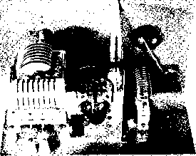 *** -ЧИР Since 15 to 20 per cent of the output from a grounded-grid r-f stage passes directly through it from the driver, it is obvious that conventional plate modulation of the output stage only will give incomplete modulation. In fact, if the plate voltage is completely removed from the g-g (grounded-grid) stage and the plate return is grounded, the energy from the driver will pass directly through the tube and appear in the output circuit. So it becomes necessary to apply modulation to the driver tube simultaneously to that which is applied to the plate of the g-g stage. It is normal practice in commercial application to modulate the driver stage about 60 per cent as much as the g-g stage. For straight c-w operation no special considerations are involved in the use of a g-g power amplifier except that it obviously is necessary that the driver stage be keyed simultaneously with the final amplifier, if the installation is such that the final amplifier is to be keyed. With excitation, keying the combination of the driver and output stage will operate quite normally. The Grounded-Grid Closs В Linear The g-g power amplifier is particularly well suited to use as a class В linear amplifier to build up the output of a lower powered SSB Transmitter. Two advantages obtained through the use of the g-g stage as a class В linear amplifier are (1) no Swamping is required in the input circuit of the g-g stage, and (2) nearly the full output of the exciter transmitter appears in the output of the g-g stage, being added to the output of the g-g amplifier. Since operating impedances are lowered when a stage is operated as a Class В linear, rather high values of tank capacitance are required for a satisfactory operating circuit Q. The load impedance presented to one 304TL with the operating conditions specified above is about 2500 ohms; hence the plate tank circuit capacitance for an operating Q of 15 should be about 180 ohms. This represents an operating plate tank capacitance of about 240 fifd. for 4 Mc, and proportionately smaller capacitances for the higher frequency bands. The cathode impedance for one 304TL under the operating conditions specified is about 700 ohms. Thus, for an operating cathode-circuit Q of 10 the cathode tank capacitance Figure 12 REAR OF THE GROUNDED-GRID AMPLIFIER HANDBOOK 304TL G-G Amplifier 165 should have a reactance of 70 ohms. This value of reactance is represented by about 550 fifdd. at 4 Mc, and proportionately smaller capacitances for higher frequencies. Since the peak cathode voltage is only about 400, quite small spacing in the cathode tank capacitor can be used. Figure 11 illustrates a practical grounded-grid amplifier, using a single 304TL tube. A bifilar wound coil is used to feed the filament voltage to the tube. Shunting inductors are used to tune the filament circuit to higher frequencies. When tuning the g-g stage, it must be remembered that the input tuned circuit is effectively in series with the output circuit as far as the output energy is concerned. Thus, it is not possible to apply full excitation power to rhe stage unless plate current is also flowing. If full excitation is applied in the absence of plate voltage, the grid of the output tube would be damaged from excessive excitation. Construction of the amplifier is illustrated in figures 12 and 13. A 3000-volt plate supply is used which should have good regulation. An output filter condenser of at least 10 microfarads should be employed for Class В operation. Class В operating bias is -260 volts, obtained from a well regulated bias supply. For operation in TV areas, additional lead filtering is required, as well as complete screening of the amplifier. 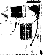 Figure 13 UNDERSIDE OF THE GROUNDED-GRID AMPLIFIER 8-7 Class ABl Radio Frequency Power Amplifiers Class ABl r-f amplifiers operate under such conditions of bias and excitation that grid current does not flow over any portion of the input cycle. This is desirable, since distortion caused by grid current loading is absent, and also because the stage is capable of high power gain. Stage efficiency is about 58% when a plate current operating angle of 210 is chosen, as compared to 62% for Class В operation. The level of static (quiescent) plate current for lowest distortion is quite critical for Class ABl tetrode operation. This value is determined by the tube characteristics, and is not greatly affected by the circuit parameters or operating voltages. The maximum d-c plate potential is therefore limited by the static dissipation of the tube, since the resting plate current figure is fixed. The static plate current of a tetrode tube varies as the 3/2 power of the screen voltage. For example, raising the screen voltage from 300 to 500 volts will double the plate current. The optimum static plate current for minimum distortion is also doubled, since the shape of the Eg-Ip curve does not change. In actual practice, somewhat lower static plate current than optimum may be employed without raising the distortion appreciably, and values of static plate current of 0.6 to 0.8 of optimum may be safely used, depending upon the amount of nonlinearity that can be tolerated. As with the class В linear stage, the minimum plate voltage swing of the class ABl amplifier must be kept above the d-c screen potential to prevent operation in the nonlinear portion of the characteristic curve. A low value of screen voltage allows greater r-f plate voltage swing, resulting in improvement in plate efficiency of the tube. A balance between plate dissipation, plate efficiency, and plate voltage swing must be achieved for best linearity of the amplifier. The S-Curve The perfect linear ampli- fier delivers a signal that is a replica of the input signal. Inspection of the plate characteristic curve of a typical tube will disclose the tube linearity under class A operating conditions (figure 14). The curve is usually of exponential shape, and the signal distortion is held to a small value byoperatiiig the tube well below its maximum output, and centering operation over the most linear portion of the characteristic curve.
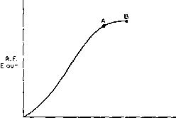 R.F. EiN Figure 14 Eg-lp CURVE Awplifier opsratian is confined to most linear portion of characteristic curve. The relationship between exciting voltage in a Class ABl amplifier and the r-f plate circuit voltage is shown in figure 15. With a small value of static plate current the lower portion of the line is curved. Maximum un-distorted output is limited by the point on the line (A) where the instantaneous plate voltage down to the screen voltage. This hook in the line is caused by current diverted from the plate to the grid and screen elements of the tube. The characteristic plot of the usual linear amplifier takes the shape of an S-curve. The lower portion of the curve is straightened out by using the proper value of static plate current, and the upper portion of the curve is avoided by limiting minimum plate voltage swing to a point substantially above the value of the screen voltage. Operating Parameters The approximate oper-for the Class ABl ating parameters may be Linear Amplifier obtained from the Con- stant Current curves (Eg-Ep) or the Eg-Ip curves of the tube in question. An operating load line is first approximated. One end of the load line is determined by the d-c operating voltage of the tube, and the required static plate current. As a starting point, let the product of the plate voltage and current equal the plate dissipation of the tube. Assuming we have a 4-400A tetrode, this end of the load line will fall on point A (figure 16). Plate power dissipation is 360 watts (3000V @ 120 ma). The opposite end of the load line will fall on a point determined by the minimum instantaneous plate voltage, and by the maximum instantaneous plate current. The minimum plate voltage, for best linearity should be considerably higher than Figure 15 LINEARITY CURVE OF TYPICAL TETRODE AMPLIFIER At point A the /nsfonfoneous plate voltage is svfinging down fo the value of screen voltage. Af point B it is swinging we be/ow fhe screen and is approaching the point where sofurofion, Or plate current limiting fakes place. the screen voltage. In this case, the screen voltage is 500, so the minimum plate voltage excursion should be limited to 600 volts. Class ABI operation implies no grid current, therefore the load line cannot cross the Eg=0 line. At the point Ep=600, Eg=0, the maximum plate current is 580 ma (Point B ). Each point the load line crosses a grid voltage axis may be taken as a point for construction of the Eg-Ip curve, just as was done in figure 22, chapter 6. A constructed curve shows that the approximate static bias voltage is-74 volts, which checks closely with point A of figure 16. In actual practice, the bias voltage is set to hold the actual dissipation slightly below the maximum figure of the tube. The single tone power output is: Emax-EminxIpmax. or ЗООР-бОО X. 58 = 348 watts The plate current-angle efficiency factor for this class of operation is 0.73, and the actual plate circuit efficiency is: ND=Emax-EminX0.73, ОГ ЗОООбОО X 0.73 = 58.4% Emax 3000 The power input to the stage is therefore Po X 100 or, 348 = 595 watts Np 58.4 The plate dissipation is: 595-348 = 247 watts. HANDBOOK AB, R.F. Power Amplifiers 167 + 2S о 0 -1S0
Figure 16 OPERATING PARAMETERS FOR TETRODE LINEAR AMPLIFIER ARE OBTAINED FROM CONSTANT-CURRENT CURVES. It can be seen that the limiting factor for this class of operation is the static plate dissipation, which is quite a bit higher than the operating dissipation level. It is possible, at the expense of a higher level of distortion, to drop the static plate dissipation and to increase the screen voltage to obtain greater power output. If the screen voltage is set at 800, and the bias increased sufficiently to drop the static plate current to 90 ma, the single tone d-c plate current may rise to 300 ma, for a power input of 900 watts. The plate circuit efficiency is 55-6%, and the power output is 500 watts. Static plate dissipation is 270 watts. At a screen potential of 500 volts, the maximum screen current is less than 1 ma, and under certain loading conditions may be negative. When the screen potential is raised to 800 volts maximum screen current is 18 ma. The performance of the tube depends upon the voltage fields set up within the tube by the cathode, control grid, screen grid, and plate. The quantity of current flowing in the screen circuit is only incidental to the fact that the screen is maintained at a positive potential with respect to the electron stream surrounding it. The tube will perform as expected so long as the screen current, in either direction, does not create undesirable changes in the screen voltage, or cause excessive screen dissipation. Good regulation of the screen supply is there- fore required. Screen dissipation is highly responsive to plate loading conditions, and the plate circuit should always be adjusted so as to keep the screen current below the maximum dissipation level as established by the applied voltage. G-G Class В Linear Certain tetrode and pentode Tetrode Amplifier tubes, such as the 6AG7, 837, and 803 perform well as grounded grid class В linear amplifiers. In this configuration both grids and the suppressor are grounded, and excitation is applied to the cathode circuit of the tube. So connected, the tubes take on characteristics of high-mu triodes. No bias or screen supplies are required for this type of operation, and reasonably linear 6AG7 TO DRIVER 7 О о о о о
В+300-700 V. Figure 17 SIMPLE GROUNDED-GRIO LINEAR AMPLIFIER 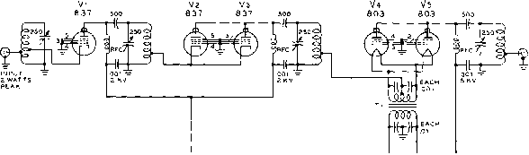 Figure 18 3-STAGE KILOWATT LINEAR AMPLIFIER FOR 80 OR 40 METER OPERATION An open frame fi/omenf transformer may be used for TI. Cathode taps are adjusted for proper excitation of following stage. operation can be had with a very minimum of circuit components (figure 17). The input impedance of the g-g stage falls between 100 and 250 ohms, eliminating the necessity of swamping resistors, even though considerable power is drawn by the cathode circuit of the g-g stage. Power gain of a g-g stage varies from approximately 20 when tubes -of the 6AG7 type are used, down to five or six for the 837 and 803 tubes. One or more g-g stages may be cascaded to provide up to a kilowatt of power, as illustrated in figure 18. The input and output circuits of cascaded g-g stages are in series, and a variation in load impedance of the output stage reflects back as a proportional change on the input circuit. If the first g-g stage is driven by a high impedance source, such as a tetrode amplifier, any change in gain will automatically be compensated for. If the gain of V4-V5 drops, the input impedance to that stage will rise. This change will reflect through V2-V3 so that the load impedance of VI rises. Since VI has a high internal impedance the output voltage will rise when the load impedance rises. The increased output voltage will raise the output voltage of each g-g stage so that the overall output is nearly up to the initial value before the drop in gain of V4-V5. The tank circuits, therefore, of all g-g stages must be resonated with low plate voltage and excitation applied to the tubes. Tuning of one stage will affect the other stages, and the input and coupling of each stage must be adjusted in turn until the proper power limit is reached. Operating Data for 4-400A Grounded Grid Linear Amplifier Experiments have been conducted by Collins Radio Co. on a grounded grid linear amplifier stage using a 4-400A tube for the h.f. region. The operating characteristics of the amplifier are summarized in figure 19. It can be noted that unusually low screen voltage is used on the tube. The use of lower screen voltage has the adverse effect of increasing the driving power, but at the same time the static plate current of the stage is decreased and linearity is im-iraproved. For grounded grid operation of the 4-400A, a screen voltage of 300 volts (filament to screen) gives a reasonable compromise between these factors.
igure HANDBOOK 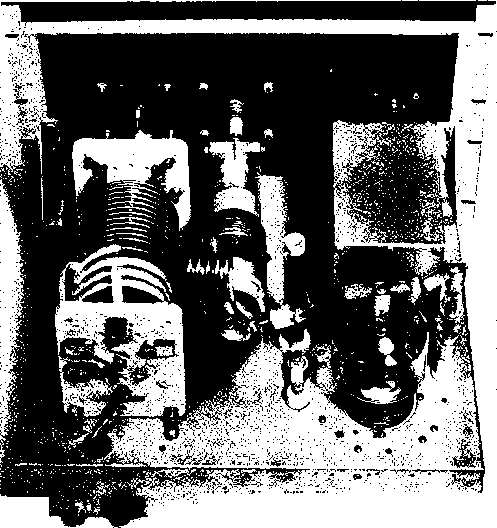 TOP VIEW OF A 4-250A AMPLJFIER Pi-network tetrode amplifier may be operated Class ABi, Class B, or applied to tube. Same general physical and mechanical des Class С by varying various potentials gn applies in each case. CHAPTER NINE The Oscilloscope The cathode-ray oscilloscope (also called oscillograph) is an instrument which permits visual examination of various electrical phenomena of interest to the electronic engineer. Instantaneous changes in voltage, current and phase are observable if they take place slowly enough for the eye to follow, or if they are periodic for a long enough time so that the eye can obtain an impression from the screen of the cathode-ray tube. In addition, the cathode-ray oscilloscope may be used to study any variable (within the limits of its frequency response characteristic) which can be converted into electrical potentials. This conversion is made possible by the use of some type of transducer, such as a vibration pickup unit, pressure pickup unit, photoelectric cell, microphone, or a variable impedance. The use of such a transducer makes the oscilloscope a valuable tool in fields other than electronics. 9-1 A Typicol Cathode-Ray Oscilloscope For the purpose of analysis, the operation of a simple oscilloscope will be described. The Du Mont type 274-A unit is a fit instrument for such a description. The block diagram of the 274-A is shown in figure 1. The electron beam of the cathode-ray tube can be moved vertically or horizontally, or the vertical and horizontal movements may be combined to produce composite patterns on the tube screen. As shown in figure 1, the cathode-ray tube is the recipient of signals from two sources: the vertical and horizontal amplifiers. The opera-rion of the cathode-ray tube itself has been covered in Chapter 4; the auxiliary circuits pertaining to the cathode-ray tube will be covered here. The VerHcol The incoming signal which is Amplifier to be examined is applied to the terminals marked Vertical Input and Ground, The Vertical Input terminal is connected through capacitor Cj (figure 2) so that the a-c component of the input signal appears across the vertical amplifier gain control potentiometer, Rj. Thus the magnitude of the incoming signal may be controlled to provide the desired deflection on the screen of vertical jpR. i ICAL FIER dir. CATHDOe-ray tube vb INTENSITy mod.. -л-о jltd horizontal , ia---------- ----rSJ----- horizontal/ sweeps! hor. in о dir. horizontal amplifier time-base generator Figure 1 BLOCK DIAGRAM, TYPE 274.A CATHODE-RAY OSCILLOSCOPE 1 ... 13 14 15 16 17 18 19 ... 80 |
||||||||||||||||||||||||||||||||||||||||||||||||||||||||||||||||||||||||||||||||||||||||||||||||||||||||||||||||||||||||||||||||||||||||||||||||||||||||||||||||||||||||||||||||||||||||||||||||||||||||||||||||||||||||||||||||||||||||||||||||||||||||||||||||||||||||||||||||||||||||||||||||||||||||||||||||||||||||||||||||||||||||||||||||||||||||||||||||||||||||||||||||||||||||||||||||||||||||||||||||||||||||||||||||||||||||||||||||||||||||||||||||||||||||||||||||||||||||||||||||||||||||||||||||||||||||||||||||||||||||||||||||||||||||||||||||||||||||||||||||||||||||||||||||||||||||||||||||||||||||||||||||||||||||||||||||||||||||||||||||||||||||||||||||||||||||||||||||||||||||||||||||||||||||||||||||||||||||||||||||
|
© 2026 AutoElektrix.ru
Частичное копирование материалов разрешено при условии активной ссылки |