 |
 |
 |
| Главная Журналы Популярное Audi - почему их так назвали? Как появилась марка Bmw? Откуда появился Lexus? Достижения и устремления Mercedes-Benz Первые модели Chevrolet Электромобиль Nissan Leaf |
Главная » Журналы » Simple coaxial reflectometer 1 ... 16 17 18 19 20 21 22 ... 80 HANDBOOK R-C Oscillators 191 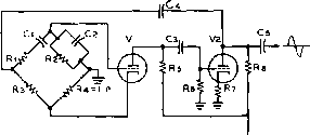 LP = R4 - 4 WATT, I 10 v. LAMP BULB Rl X Cl =R2 X Сг Figure 15 THE WIENBRIDGE AUDIO OSCILLATOR 40CilUF 400UUF 400JUUF N : jZOOK f200K $2 lOOK iOOb :200K ±r IK I2AX7 Figure 16 THE PHASE-SHIFT OSCILLATOR A step-counter is similar to the circuits discussed, except that a capacitor which is large compared to C, replaces the diode load resistor. The charge of this condenser is increased during the time of each pulse, producing a step voltage across the output (figure 13). A blocking oscillator may be connected to a step-counter, as shown in figure 14. The oscillator is triggered into operation when the voltage across Cj reaches a point sufficiently positive to raise the grid of V, above cutoff. Circuit parameters may be chosen so that a count division up to 1/20 may be obtained with reliability. 10-6 Resistance-Capacity Oscillators In an R-C oscUlator, the frequency is determined by a resistance capacity network that provides regenerative coupling between the output and input of a feedback amplifier. No use is made of a tank circuit consisting of inductance and capacitance to control the frequency of oscillation. The Wien-Bridge oscillator employs a Wiert network in the R-C feedback circuit and is shown in figure 15. Tube Vi is the oscillator tube, and tube Vj is an amplifier and phase-inverter tube. Since the feedback voltage through c4 produced by Vj is in phase with the input circuit of V, at all frequencies, oscillation is maintained by voltages of any frequency that exist in the circuit. The bridge circuit is used, then, to eliminate feedback voltages of all frequencies except the single frequency desired at the output of the oscillator. The bridge allows a voltage of only one frequency to be effective in the circuit because of the degeneration and phase shift provided by this circuit. The frequency at which oscillation occurs is: 2ff Rl Cl , when R, X Cl = Rj X Cj A lamp Lp is used as the cathode resistor of V, as a thermal stabilizer of the oscillator amplitude. The variation of the resistance with respect to current of the lamp bulb holds the oscillator output voltage at a nearly constant amplitude. The phase-shift oscillator shown in figure 16 is a single tube oscillator using a three section phase shift network. Each section of the network produces a phase shift in proportion to the frequency of the signal that passes through it. For oscillations to be produced, the signal from the plate of the tube must be shifted 180°. Three successive phase shifts of 60* accomplish this, and the frequency of oscillation is determined by this phase shift. A high-mu triode or a pentode must be used in this circuit. In order to increase the frequency of oscillation, either the resistance or the capacitance must be decreased. 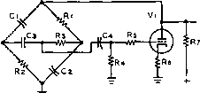 Figure 17 THE BRIDGE-TYPE PHASE-SHIFT OSCILLATOR 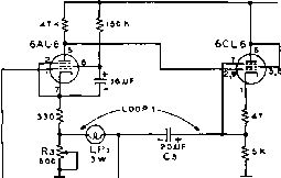  Figure 18 THE NBS BRIDGE-T OSCILLATOR CIRCUIT AS USED IN THE HEATH AG-9 AUDIO GENERATOR NOTCHFREQUENCY F=-!- гя-RC WHERE 9 C=VCi Сг Rt i Re NOTCH- NETWORK -fre<3. of oscillation -/nes f/b =pos f/b posit ive -feedback {LOOP 1 ) 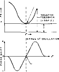 phase shift = 0 Figure 19 BRIDGE-T FEEDBACK LOOP CIRCUITS Oscillation will occur of the null frequency of the bridge, at which frequency the bridge allows minintum degeneration in loop 2. A bridge-type phase shift о scillator is shown in figure 17. The bridge is so proportioned that at only one frequency is the phase shift through the bridge 180 . Voltages of other frequencies are fed back to the grid of the tube out of phase with the existing grid signal, and are cancelled by being amplified out of phase. The NBS Bridge-T oscillator developed by the National Bureau of Standards consists of a two stage amplifier having two feedback loops, as shown in figure 18. Loop 1 consists of a regenerative cathode-to-cathode loop, consisting of Lp, and C3. The bulb regulates the positive feedback, and tends to stabilize the output of the oscillator, much as in the manner of the Wien circuit. Loop 2 consists of a grid-cathode degenerative circuit, containing the bridge-T. Oscillation will occur at the null frequency of the bridge, at which frequency the bridge allows minimum degeneration in loop 2 (figure 19)- 10-7 Feedback Feedback amplifiers have been d i s с u s s e d in Chapter 6, section 15 of this Handbook. A more general use of feedback is in automatic control and regulating systems. Mechanical feedback has been used for many years in such forms as engine speed governors and steering servo engines on ships. A simple feexlback system for temperature control is shown in figure 20. This is a cause and effect system. The furnace (F) raises the room temperature (T) to a predetermined value at which point the sensing thermostat (TH) reduces the fuel flow to the furnace. When the room temperature drops below the predetermined value the fuel flow is increased by the thermostat control. An interdependent control system is created by this arrangement: the room temperature depends upon the thermostat action, and the thermostat action depends upon the room temperature. This sequence of events may be termed a closed loop feedback system. FURNACE (F) ROOM TEMPERATURE THERMOSTAT (TH) ,  FUEL SUPPLY FEEDBACK (ERROR SIGNAL ) Figure 20 SIMPLE CLOSED LOOP FEEDBACK SYSTEM Room temperature (T) controls fuel supply to furnace (F)by feedback loop through Thermostat (TH) control. 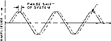 INPUT S luNAL OUTPUT SISNAL
Figure 21 PHASE SHtFT OF ERROR SIGNAL MAY CAUSE OSCILLATION INCLOSED LOOP SYSTEM To prevent oscillation, the gain of the feedback loop must be less than unity when the phase shift of the system reaches 180 degrees. Error Cancellotion A feedback control system is dependent upon a degree of error in the output signal, since this error component is used to bring about the correction. This component is called the error signal. The error, or deviation from the desired signal is passed through the feedback loop to cause an adjustment to reduce the value of the error signal. Care must be taken in the design of the feedback loop to reduce over-control tendencies wherein the correction signal would carry the sytem past the point of correct operation. Under certain circumstances the new error signal would cause the feedback control to overcorrect in the opposite direction, resulting in hunting or oscillation of the closed loop system about the correct operating point. Negative feedback control would tend to damp out spurious system oscillation if it were not for the time lag or phase shift in the system. If the overall phase shift is equal to one-half cycle of the operating frequency of the system the feedback will maintain a steady state of oscillation when the circuit gain is sufficiently high, as shown in figure 21. In order to prevent oscillation, the gain figure of the feedback loop must be less than unity when the phase shift of the system reaches 180 degrees. In an ideal control system the gain of the loop would be constant throughout the operating range of the device, and would drop rapidly outside the range to reduce the bandwidth of the control system to a minimum. The time lag in a closed loop system may be reduced by using electronic circuits in place of mechanical devices, or by the use of special circuit elements having a phase-lead characteristic. Such devices make use of the properties of a capacitor, wherein the current leads the voltage applied to it. CHAPTER ELEVEN Electronic Computers Mechanical computing machines were first produced in the seventeenth century in Europe although the simple Chinese abacus (a digital computer) had been in use for centuries. Until the last decade only simple mechanical computers (such as adding and bookkeeping machines) were in general use. The transformation and transmission of the volume of information required by modern technology requires that machines assume many of the information processing systems formerly done by the human mind. Computing machines can perform routine operations more quickly and more accurately than a human being, processing mathematical and logistical data on a production hne basis. The computer, however, cannot create, but can only follow instructions. If the instructions are in error. 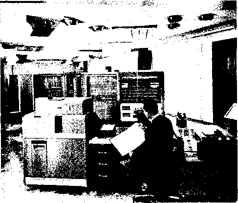 THE IBM COMPUTER AND MEMORY The 704 Computer is used with 32,000 word memory storage unit for research programs. Heart of this auxiliary unit are small, doughnut-shaped iron ferrites which store information by means of magnetism. The unit is the first of Hs kind to be Installed with IBMs 704 computer. Components of the system seen in the foreground are (left) card punch and (right) card reader. In the center of the picture is the 704$ processing unit. Digital Computers 195 north snore
JOf/r/ shore Figure 1 SIMPLE PUZZLES IN LOGIC MAY BE SOLVED BY ELECTRIC COMPUTER. THE FARMER AND RIVER COMPUTER IS SHOWN HERE. the computer will produce a wrong answer. Computers may be divided into two classes: the digital and the analog. The digital computer counts, and its accuracy is limited only by the number of significant figures provided for in the instrument. The analog с omputer measures, and its accuracy is limited by the percentage errors of the devices used, multiplied by the range of the variables they represent. 11-1 Digital Comput-ers The digital computer operates in discrete steps. In general, the mathematical operations are performed by combinations of additions. Thus multiplication is performed by repeated additions, and integration is performed by summation. The digital computer may be thought of as an on-off device operating from signals that either exist or do not exist. The common adding machine is a simple computer of this type. The on-off or yes-no type of situation is well suited to switches, electrical relays, or to electronic tubes. A simple electrical digital computer may be used to solve the old farmer and river problem. The farmer must transport a hen, a bushel of corn, and a fox across a river in a small boat capable of carrying the farmer plus one other article. If the farmer takes the fox in the boat with him, the hen will eat the corn. On the other hand, if he takes the corn, the fox will eat the hen. The circuit for a simple computer to solve this problem is shown in figure 1. When the switches are moved from south shore to north shore in the proper sequence the warning buzzer will not sound-An error of choice will sound the buzzer, A second simple digital computer is shown is figure 2. The problem is to find the three NOTE; all buttons have one normally open contact and one normally closed contact. Figure 2 A SEQUENCE COMPUTER. Thiee correct buttons will sound the buzzer. proper push buttons that will sound the buzzer. The nine buttons are mounted on a board so that the wiring cannot be seen. Each switch of these simple computers executes an on-off action. When applied to a logical problem yes-no may be substituted for this term. The computer thus can act out a logical concept concerned with a simple choice. An electronic switch (tube) may be substituted for the mechanical switch to increase the speed of the computer. The early computers, such as the ENIAC (Electronic Numerical Integrator and Calculator) employed over 18,000 tubes for memory and registering circuits capable of remembering a 10-digit number. 11-2 Binary Notation To simply and reduce the cost of the digital computer it was necessary to modify the system of operation so that fewer tubes were used per bit of information. The ENIAC-type computer requires 50 tubes to register a 5-digit number.
Figure 3 BINARY NOTATION MAY BE USED FOR DIGITAL DISPLAY. BINARY BOARD ABOVE INDICATES 73092.
Figure 4 BINARY DECIMAL NOTATION. ONLY FOUR TUBES ARE REQUIRED TO REPRESENT DIGITS FROM 1 TO 15. THE DIGIT 12 IS INDICATED ABOVE. The tubes (or their indicator lamps) can be arranged in five columns of 10 mbes each. From right to left the columns represent units, tens, hundreds, thousands, etc. The bottom tube in each column represents zero, the second tube represents one, the third tube two, and so on. Only one tube in each column is excited at any given instant. If the number 73092 is to be displayed, tube number seven in the fifth column is excited, tube number three in the fourth column, tube number zero in the third column, etc. as shown in figure 3. A simpler system employs the binary decimal notation, wherein any number from one to fifteen can be represented by four tubes. Each of the four tubes has a numerical value that is associated with its position in the tube group. More than one tube of the group may be excited at once, as illustrated in figure 4. The values assigned to the tubes in this particular group are 1, 2, 4, and 8, Additional tubes may be added to the group, doubling the notation of the tube thus: 1, 2, 4, 8, 16, 32, 64, 128, 356, etc. Any numerical value lower than the highest group number can be displayed by the correct tube combination. A third system employs the binary notation which makes use of a bit (binary digit) representing a single morsel of information. The binary system has been known for over forty centuries, and was considered a mystical revelation for ages since it employed only two sym-
Figure 5 BINARY NOTATION SYSTEM REQUIRES ONLY TWO NUMBERS, 0 AND 1. bols for all numbers- Computer service usually employs zero and one as these symbols. Decimal notation and binary notation for common numbers are shown in figure 5- The binary notation represents 4-digit numbers (thousands) with ten bits, and 7-digit numbers (millions) with 20 bits. Only one electron tube is required ro display an information bit. The savings in components and primary power drain of a binary-type computer over the older ENIAC-type computer is obvious-Figure 6 illustrates a computer board showing the binary indications from one to ten. Digital Computer Uses The digital computer is employed in a yes-no situation. It may be used for routine calculations that would ordinarily require enormous man-hours of time, such as checking stress estimates in aircraft design, or military logistics, and problems involving the manipulation of large masses of figures.
Figure 6 BINARY NOTATION AS REPRESENTED ON COMPUTER BOARD FOR NUMBERS FROM 1 TO 10. HANDBOOK Analog Computers 197 eouT eao- -vw- eouT - -- { e-iRi , ег R2 \ f R3 \[Rn.R2] + R3/ Figure 7 SUMMATION OF TWO VOLTAGES BY ELECTRICAL MEANS. 11-3 Analog Computers The analog computer represents the use of one physical system as a model for a second system that is usually more difficult to construct or to measure, and that obeys the equations of the same form. The term analog implies similarity of relations or properties between the two systems. The common slide-rule is a mechanical analog computer. The speedometer in an automobile is a differential analog computer, displaying information proportional to the rate of change of speed of the vehicle. The electronic analog computer employs circuits containing resistance, capacitance, and inductance arranged to behave in accordance with analogous equations. Variables are represented by d-c voltages which may vary with time. 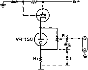 eour = ea+et EouT 84- еоит=к(е1±ег) Figure 8 SUMMATION OF TWO VOLTAGES BY ELECTRONIC MEANS. Thus complicated problemis can be solved by d-c amplifiers and potentiometer controls in electronic circuits performing mathematical functions. Addition and If a linear network is ener-SubtTocHon gized by two voltage sources the voltages may be summed as shown in figure 7- Subtraction of quantities may be accomplished by using negative and positive voltages, A-c voltages may be employed for certain additive circuits, and raore THE HEATHKIT ELECTRONIC ANALOG DIGITAL COMPUTER This electronic slide rule s/mu-lates equations or physical problems electronically, Substituting one physical system as a model for a second system that is usually more difficult or costly to construct or measure, and that obeys equations of the same form. 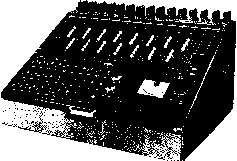 eouT = X ei eour Figure 9 ELECTRONIC MULTIPLICATION MAY BE ACCOMPLISHED BY CALIBRATED POTENTIOMETERS, WHEN OUTPUT VOLTAGE IS PROPORTIONAL TO THE INPUT VOLTAGE MULTIPLIED BY A CONSTANT (R2/R1). complex circuits employ vacuum tubes, as in figure 8. Synchronous transformers may be used to add expressions of angular rotation, and circuits have been developed for adding time delays, or pulse counting. MulHpiicaHon Electronic multiplication and and Division division may be accomplished with the use of potentiometers where the output voltage is proportional to the input voltage multiplied by a constant which may be altered by changing the physical arrangement of the potentiometer (figure 9). Variable autotransformers may also be used to perform multiplication. A simple bridge may be used to obtain an output that is the product of two inputs divided by a third input, as shown in figure 10. Differentiation The time derivative of a voltage can be expressed as a charge on a capacitor by: dt (1) and is shown in figure 11 A. The charging current is converted into a voltage by the use of a resistor, R. If the input to the RC circuit is charging at a uniform rate so that the current through С and R is constant, the output voltage eo is: i = C OUTPUT \j Rl X Ra 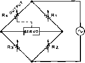 Figure 10 ELECTRONIC MULTIPLICATION BY BRIDGE CIRCUIT PROVIDES OUTPUT THAT IS PRODUCT OF TWO INPUTS DIVIDED BY A THIRD INPUT. e o- eouT о -M/-t- ® (D Figure 11 ELECTRONIC DIFFERENTIATION The time derivative of a voltage can be expressed as a charge on a capacitor (A). Operational amplifier (B) employs feed bock principle for short differentiation time. eo = RC de dt For highest accuracy, a small RC product should be used, permitting the maximum possible differentiation time. The output of the differentiator may be amplified to any suitable level. A more accurate differentiating device makes use of an operational amplifier. This unit is a high gain, negative feedback d-c amplifier (discussed in section 11-4) with the resistance portion of the RC product appearing in the feedback loop of the amplifier (figure IIB). A shorter differentiation time may be employed if the junction point between R and С could be held at a constant potential. The feedback amplifier shown inverts the output signal and applies it to the RC network, holding the junction potential constant. Integration Integration is a process of accumulation, or summation, and requires a device capable of storing physical quantities. A capacitor will store an electrical charge and will give the time integral of a current in respect to a voltage: - 1 -л Co--1 dt с In most computers, the input signal is in the form of a voltage, and the input charging current of the capacitor must be taken through a series resistance as in figure 12. If the integrating time is short the charging current is approximately proportional to the input voltage. The charging current may be made a true measure of the input voltage by the use Figure 12 SIMPLE INTEGRATION CIRCUIT Making use of charging current of capacitor. eouT HANDBOOK Operational Amplifier 199 eouT Figure 13 MILLER FEEDBACK INTEGRATOR SUITABLE FOR COMPUTER USE. о-OW-J- e in eouT Figure 14 R-L NETWORK USED FOR INTEGRATION PURPOSES. Figure 15 OPERATIONAL AMPLIFIER (-A) Mathematical operations may be performed by any operational amplifier, usually a stable, high-gain d-c omplifier, such as shown in Figure 16. of an operational amplifier wherein the capacitance portion of the RC product appears in the feedback loop of the amplifier, holding the junction point between R and С at a constant potential. A simple integrator is shown in figure 13 employing the Miller feedback principle. Integration is also possible with an RL network (figure 14). 11-4 The Operational Amplifier Mathematical operations are performed by using a high gain d-c amplifier, termed an operational amplifier- The symbol of this unit is a triangle, with the apex pointing in the direction of operation (figure 15). The gain of such an amplifier is A, so: Co - ~ Ack, or eg - If ~A approaches infinity, eg will be approximately zero. In practice this condition is realized by using amplifiers having open loop gains of 30,000 to 60,000. If е is set at 100 volts, e? will be of the order of a few millivolts. Thus, considering eg equal to zero: ei Ri or eo - ei which may be written: Co - Kei, where К - This amounts to multiplication by a constant coefficient, since Ri and Ri may be fixed in value. The circuit of a typical operational amplifier is shown in figure 16. Amplifier Two voltages may be added by Operation the amplifier, as shown in figure 17. Keeping in mind that eg is 1 M {Rf) о-Ш-i--fcj-J 100 к e/i>vwk- м^RF) -W- £гм 12АЛ7- 420 к| eBQ/A- 3) ,00001 ?гм {BALANCE) iso к {sain) 9М 2М i м -обо г.7к 5150К 6ВН6 1 к лоа гг 5гго )NE-51 -----GAIN = - А - Figure 16 HIGH GAIN OPERATIONAL AMPLIFIER, SUCH AS USED IN HEATH COMPUTER. о Rl -тЛАЛ- Figure 17 TWO VOLTAGES MAY BE ADDED BY SUMMATION AMPLIFIER. essentially at zero (ground) potential: Rt , Rf eo = - -e2+-- Rl Ki or, Co ,here K, = ;-andK.-i As long as Co does not exceed the input range of the amplifier, any number of inputs may be used: Rf , Rf , , Rf кГ + =+ -+rT (10) So = - Rf + (11) Integration is performed by replacing the feedback resistor Rf with a capacitor Cf, as shown in figure 18. For this circuit (with e approximately zero): (12) , dg deo J ei dco but g=Cf е., so-- Cfand -- О Thus: deo - RiCf ei dt Ri Cf (13) (14) (15) es 1 Figure 18 INTEGRATION -o Performed by Go Summation Amplifier by replacing feed back resistor with a capacitor. Figure 19 MASS-SPRING-DAMPER PROBLEM MAY BE SOLVED BY ELECTRICAL ANALOGY WITH SIMPLE COMPUTER. 11-5 Solying Analog Problems By combining the above operations in various ways, problems of many kinds may be solved For example, consider the mass-spring-damper assembly shown in figure 19- The mass M is connected to the spring which has an elastic constant K. The viscous damping constant is С The vertical displacement is y. The sum of the forces acting on mass M is: f (t) =M + C + Ky (16) where f (t) is the applied force, or forcing function. The first step is to set up the analog computer circuit so as to obtain an output voltage proportional to у for a given input voltage proportional to f (t). Equation (16) may be rewritten in the form: dV dy Ky + f (t) (17) If, in the analog circuit, there is a voltage equal to M dy . dy , , it can be converted to dt dt by passing it through an integrator circuit having an RC time constant equal to M, This resulting voltage can be passed through a second integrator stage with unit time constant which will have an output volage equal to y. The voltages representing y, ---, and f (t) can then be summed to give ~ С Ky + f (t) which is the right hand side of equation (17), and therefore equal to M . Connecting the 1 ... 16 17 18 19 20 21 22 ... 80 |
||||||||||||||||||||||||||||||||||||||||||||||||||||||||||||||||||||||||||||||||||||||||||||||||||||||||||||||||||||||||||||||||||||||||||||||||||||||||||||||||||||||||||||||||||||||||||||||||||||||||||||
|
© 2026 AutoElektrix.ru
Частичное копирование материалов разрешено при условии активной ссылки |