 |
 |
 |
| Главная Журналы Популярное Audi - почему их так назвали? Как появилась марка Bmw? Откуда появился Lexus? Достижения и устремления Mercedes-Benz Первые модели Chevrolet Электромобиль Nissan Leaf |
Главная » Журналы » Simple coaxial reflectometer 1 ... 17 18 19 20 21 22 23 ... 80 HANDBOOK Analog Problems 201 fit) > OPERATE RELAY -wv- OPERATE RELAY 1 m -iW- set voltage to Y = YO at time t=0 (initial displacement) -C-Kr+fii) TO DISPLAY OSCILLOSCOPE Figure 20 ANALOG SOLUTION FOR MASS-SPRING-DAMPER PROBLEM OF FIGURE 19. output of the summing amplifier (A3) to the input of the first as shown in figure 20 satisfies the equation. To obtain a solution to the problem, the initial displacement and velocity must be specified. This is done by charging the integrating capacitors to the proper voltages. Three operational amplifiers and a summing amplifier are required. A second problem that may be solved by the analog computer is the example of a freely falling body. Disregarding air resistance, the body will fall (due to the action of gravity) with a constant acceleration. The equation describing this action is: F mg-m (18) Integration of equation (18) will give the velocity, or ~~ , and integration a second time dt will give displacement, or y. The block diagram of a suitable computer for this problem is shown in figure 21. If a voltage proportional to g and hence to is introduced into the first amplifier, the output of that unit will be -A, dt or the :d±V
Figure 21 ANALOG COMPUTER FOR FREELY FALLING BODY PROBLEM. velocity. That, in turn, will become y, or distance, at the output of the second amplifier. Before the problem can be solved on the computer it is necessary to determine the time of solution desirable and the output amplitude of the solution. The time of solution is determined by the RC constant of the integrating amplifiers. If RC is set at unity, computer time is equal to real time. The computer time desirable is determined by the method of readout. When using an oscilloscope for read-out, a short solution time is desirable. For a recorder, longer solution time is better. Suppose, for example, in the problem of the falling body, the distance of fall in 2.5 seconds is desired. Using an RC constant of 1 would give a solution time of 2.5 seconds. This would be acceptable for a recorder but is slow for an oscilloscope. A convenient time of solution for the scope would be 25 milliseconds. This is 1/100 of the real time, so an RC constant of .01 is needed. This can be obtained with С equal to 0.1 jnfd, and R equal to 100,000 ohms. It is now necessary to choose an input voltage which will not overdrive the amplifiers. The value of g is known to be approximately 32 ft/sec./sec. A check indicates that if we set g equal to 32 volts, the voltage representing the answer will exceed 100 volts. Since the linear response of the amplifier is only 100 volts, this is undesirable. An input of 16 volts, however, should permit satisfactory operation of the amplifiers. Output voltages near zero should also be avoided. In general, output voltage should be about 50 volts or so, with amplifier gains of 20 to 60 being preferable-Thus, for this particular problem the time-scale factor and amplitude-scale factor have 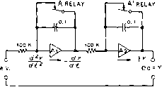 + 100 V.o Figure 22 ANALOG SOLUTION FOR FALLING BODY PROBLEM OF FIGURE 21. TIME IN SECONDS -► i г (£.5) 3 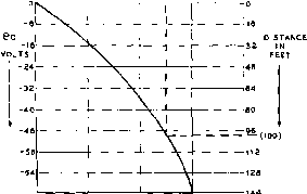 Figure 23 READ-OUT SOLUTION OF FREELY FALLING BODY PROBLEM. been chosen. The problem now looks like figure 22. To solve the problem, relays A and A are opened. The solution should now appear on the oscilloscope as shown in figure 23- The solution of the problem leaves the integrating capacitors charged. It is necessary to remove this charge before the problem can be rerun. This is done by closing relays A and A. 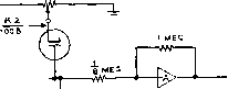 g, о-- o-eo too в -100 v.o-ЛЛ/ Figure 24 UMITING CIRCUIT TO SIMULATE NON-LINEAR FUNCTIONS SUCH AS ENCOUNTERED IN HYSTERESIS, BACKLASH, AND FRICTION PROBLEMS. 11-6 Non-linear Functions Problems are frequently encountered in which non-linear functions must be simulated. Non-linear potentiometers may be used to supply an unusual voltage source, or diodes may be used as limiters in those problems in which a function is defined differently for different regions of the independent variable. Such a function might be defined as follows: eo = - Ki, е> - К. (19) eo = ei, -К ei К. (20) ео = К2,е. К. (21) where Ki and Кг are constants. Various limiting circuits can be used, one of which is shown in figure 24. This is a series limiter circuit which is simple and does not require special components. Commonly encountered problems requiring these or similar limiting techniques include hysteresis, backlash, and certain types of friction. INITIAL CONDITION SUPPLV  1 MEG RAMP-FUNCTION GENERATOR SLOPE CONTROL  INPUT NOTE: e£PLAC£ С WITH A I MEG RESISTOe FOR FUNCTION SETUP -OX - OUTPUT BREAK CONTROL VOLTAGE 1 MEG SIGN CHANGING AMPLIFIER -O Y-OUTPUT SUMMING AMPLIFIER Figure 25 SIMPLIFIED DIAGRAM OF FUNCTIONAL GENERATOR TO APPROXIMATE NON-LINEAR FUNCTIONS. HANDBOOK Non-Linear Functions 203 Г Xl Хг ХЭ X4 X5 Xe+X- Figure 26 TYPICAL NON-LINEAR FUNCTION WHICH MAY BE SET UP WITH FUNCTION GENERATOR. The Function A function generator may be Generator used to approximate almost any non-linear function. This is done by use of straight line segments which are combined to approximate curves such as are found in trigonometric functions as well as in stepped functions. In a typical generator ten line segments are used, five in the plus-x direction, and five in the minus-x direction. Five 6AL5 double diodes are used. Each hne segment is generated by a modified bridge circuit (figure 25). A ramp function or voltage is fed into one arm of the bridge while the opposite arm Is connected to a biased diode. The other two arms of the bridge combine to form the output. The voltage appearing across one of these arms is fed through a sign-changing amplifier and then summed with the voltage appearing at the opposite arm. If the arm of potentiometer P (the slope control) is set in the center, the bridge will be balanced and -AND GATES 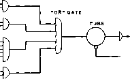 POSITIVE О . NEGATIVE Figure 27 ELECTRONIC PACKAGE IN DIGITAL COMPUTER. Sty/ized diagram of tube pacfcage. Lines carrying negative pulses are marked by a small circle at eac/i end. Gates are indicated by a semi-circle with pins for each input. the output of the summing amplifier will be zero. If, on the other hand, potentiometer P is adjusted one way or the other from center, the bridge will be unbalanced and the summing amplifier output will vary linearly with respect to the input in either a positive or negative у direction, depending upon which side of center potentiometer P Is set. The break voltage, or value of x at which a straight line segment will begin is set by biasing the diode to the particular voltage level or value of x desired. The ramp function generator has either a positive or negative input which because of the 180 degree phase shift in the amplifier, gives a minus- or plus-x output respectively. A typical function such as shown in figure 26 may be set up with the function generator. The initial condition volt- IBtAs new 608, the first completely transistorized calculator for commercial applications, operates without the use of a single vacuum tube. Transistors-tiny germanium devices thot perform many of the functions of conventional vacuum tubes -make possible 50% reduction in computer-unit size and a 90% reduction in power reguirements over a comparable IBM tube-model machine. They are mounted, along with reloted circuitry, on banks of printed wiring panels in the 608. The machines internal storage, or memory, is made up of magnetic cores-minute, doughnut-shaped objects that can remember information indefinitely, and recall it tor use in calculations in a few millionths of a 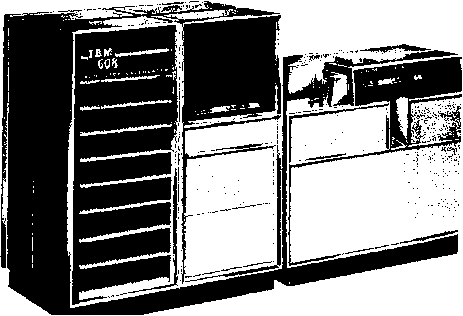 age is set to the value of Xi. The break-voltage control is increased until the output of the summing amplifier increases abruptly, indicating the diode is conducting. The input voltage from the initial condition power supply is set to the value X2 The slope control (P) is now set to value Y2. A second function generator may be used to set points Хз and X*, using the break-voltage control and the initial condition voltage adjustments. Points Xs and Xc are finally set with a third generator. The x-output of the function generator system may be read on an oscilloscope, using the x-output of the ramp-function generator amplifier as the horizontal sweep for the oscilloscope. 11-7 Digital Circuitry Digital circuits dealing with and, or, and not situations may be excited by electrical pulses representing these logical operations. Sorting and amplifying the pulses can be accomplished by the use of electronic packages, such as shown in figure 27. Logical operations may be accomplished by diode-resistor gates operating into an amplifier stage. Negative and positive output pulses from the amplifier are obtained through diode output gates. The driving pulses may be obtained from a standard oscillator, operating at or near 1 mc. A circuit of a single digital package is shown in figure 28. Other configurations, such as a flip-flop may be used. Many such packages can be connected in series to form operational circuits. The input and and or gates are biased to conduction by external voltages. The and diode gate transmits a pulse only when all the input terminals are pulsed positively, and the or diode gate transmits a positive pulse applied to any one of its input terminals. The input pulses pass through the gates and drive the amplifier stage, which delivers an amplified pulse to the positive and negative ourput gates, and to accompanying memory circuits. Memory Circuits A memory circuit consists of some sort of delay line which is capable of holding an information pattern for a period of time. A simple electrical delay line capable of holding a pulse for a fraction of a microsecond is shown in figure 29. The amount of delay is proportional to the frequency of the input signal as shown in the graph. A long transmission line may also be used as a delay line, with the signal being removed from the far end of the line after being delayed an interval equal to the time of transmission along the line. Lines of this type are constructed much in the manner of a standard coaxial cable, except that the inner conductor is a long, thin coil as illustrated in figure 30. Other memory circuits make use of magnetostrictive or piezoelectric effects to retard the pulse. Information may also be stored in electrostatic storage tubes, upon mag- ->AND* GATES INPUT* INPUT Z о- NPUT*3 0- INPUT*4 о- INPUT*5 о- lNPUT*e о- INPUT* e о OR CLAMPING GATE DIODES 6AN5  с. о о о LIMITING DIODES ® POSITIVE PULSE NEGATIVE PULSE Figure 28 TYPICAL DIGITAL PACKAGE SHOWING INPUT AND OUTPUT DIODE GATES AND PULSE AMPLIFIER. HANDBOOK Digital Circuitry 205 INPUT J OUTPUT VINYL JACKET 12 3 4 5 f(MC) Figure 29 SIMPLE DELAY LINE COMPOSED OF LUMPED INDUCTANCE AND CAPACITANCE. GRAPH SHOWS HOW DELAY TIME VARIES WITH FREQUENCY OF INPUT PULSE. netic recording tape, and in ferromagnetic cores. Experimental magnetic cores have been developed that will permit construction of INNER CONDUCTOR WOUND AROUMD POLYETHYLENE CORE- 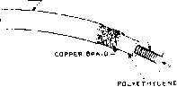 Figure 30 UNIFORM DELAY LINE BEARS RESEMBLANCE TO COAXIAL CABLE, EXCEPT FOR COILED INNER CONDUCTOR. memories capable of retaining over 10,000 separate bits of information. The memory may be read or interrogated by sending pulses through the matrix and observing the resulting induced voltage in a secondary circuit. The output from the memory circuit may be used to excite a program control system, permitting the computer to drive another mechanism in the proper sequence. Е & Е TECHNI-SHEET TABLE OF ALUMINUM TUBING, ROUND DRAWN, 12 FOOT LENGTHS
TENSILE STRENGTH BUT CANNOT BE FLATTENED OR BENT. CHAPTER TWELVE Radio Receiver Fundamentals A conventional reproducing device such as a loudspeaker or a pair of earphones is incapable of receiving directly the intelligence carried by the carrier wave of a radio transmitting station. It is necessary that an additional device, called a radio receiver, be placed between the receiving antenna and the loudspeaker or headphones. Radio receivers vary widely in their complexity and basic design, depending upon the intended application and upon economic factors. A simple radio receiver for reception of radiotelephone signals can consist of an earphone, a silicon or germanium crystal as a carrier rectifier or demodulator, and a length of wire as an antenna. However, such a receiver is highly insensitive, and offers no significant discrimination between two signals in the same portion of the spectrum. On the other hand, a dual-diversity receiver designed for single-sideband reception and employing double or triple detection might occupy several relay racks and would cost many thousands of dollars. However, conventional communications receivers are intermediate in complexity and performance between the two extremes. This chapter is devoted to the principles underlying the operation of such conventional communications receivers. 12-1 Detection or Demodulation A detector or demodulator is a device for removing the modulation (demodulating) or detecting the intelligence carried by an incoming radio wave. Radiotelephony Figure 1 illustrates an ele-Demodulatlon mentary form of radiotelephony receiver employing a diode detector. Energy from a passing radio wave will induce a voltage in the antenna and cause a radio-frequency current to flow from antenna to ground through coil Lj. The alternating magnetic field set up around L, links with the turns of Lj and causes an t-f current to flow through the parallel-tuned circuit, l2-C1, When variable capacitor Cj is adjusted so that the tuned circuit is resonant at the frequency of the applied signal, the r-f voltage is maximum. This r-f voltage is applied to the diode detector where it is rectified into a varying direct current and passed through the earphones. The variations in this current correspond to the voice modulation placed on the signal at the transmitter. As the earphone diaphragms vibrate back and forth in accord- 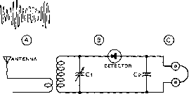 X Lt Lz - GROUND Figure 1 ELEMENTARY FORM OF RECEIVER This is t/ e basis of the crystal set type of receiver, although a vacuum diode may be used in place of the crystal diode. The tank circuit Lj-Cj IS tuned to the frequency it is desired to receive. The by-pass capacitor across the phones should have a low reactance to fhe carrier frequency being received, but a high reactance to the modulation on the received signal. О О О О О 7г Е МЛЛг- COILS WOUND IN SAME DIRECTION  AUDIO OUTPUT PLATE-TICKLER REGENERATION WITH THROTTLE* CONDENSER REGENERATION CONTROL. О о о о о 7Г AUDIO OUTPUT 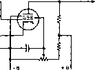 CATHODE-TAP REGENERATION WITH SCREEN VOLTAGE REGENERATION CONTROL. ance with the pulsating current they audibly reproduce the modulation which was placed upon the carrier wave. The operation of the derecror circuir is shown graphically above the detector circuit in figure 1. The modulated carrier is shown at A, as it is applied to the antenna. В represents the same carrier, increased in amplitude, as it appears across the tuned circuit. In С rhe varying d-c output from the detector is seen. Figure 2 REGENERATIVE DETECTOR CIRCUITS Regeneroffve defectors are seldom used at fhe pre-sertt time due fo their poor selectivity. However, they do illustrate fhe sinplesf type of receiver which may be used either for radiophone or radio-telegraph reception. Radiotelegraph/ Since a c-w Telegraphy sig-Reception nal consists of an unmodu- lated carrier which is interrupted to form dots and dashes, it is apparenr thar such a signal would not be made audible by detection alone. While the keying is a form of modulation, it is composed of such low frequency components that rhe keying envelope itself is below the audible range for hand keying speeds. Some means must be provided whereby an audible tone is heard while the unmodulated carrier is being received, the tone sropping immediately when the carrier is interrupted. The most simple means of accomplishing this is ro feed a locally generated carrier of a slighrly different frequency into the same detector, so that the incoming signal will mix wirh ic to form an audible beat note. The difference frequency, or heterodyne as the beat note is known, will of course stop and start in accordance with rhe incoming c-w radiotelegraph signal, because the audible heterodyne can exist only when both rhe incoming and the locally generared carriers are present. The Autodyne The local signal which is used Detector to beat with the desired c-w signal in the detector may be supplied by a separate low-power oscillaror in the receiver itself, or the detector may be made to self-oscillate, and rhus serve the dual purpose of detector and oscillator. A detector which self-oscillates to provide a bear note is known as an autodyne detector, and the process of obtaining feedback between the detector plate and grid is called regeneration. An autodyne detector is most sensitive when it is barely oscillating, and for this reason a regenerarion conrrol is always included in the circuit to adjust the feedback to the proper amounr. The regeneration control may be either a variable capaciror or a variable resistor, as shown in figure 2. With the detector regenerative but not os-cillaring, it is also quite sensitive. When the circuit is adjusted to operate in this manner, modulated signals may be received with considerably greater strengrh dian wirh a non-regenerative detector. HANDBOOK Superregenerative Detectors 209 12-2 Superregenerative Receivers At ultra-high frequencies, when it is desired to keep weight and cost at a minimum, a special form of the regenerative receiver known as the superregenerator is often used for radiotelephony reception. The superregen-erator is essentially a regenerative receiver with a means provided to throw the detector rapidly in and out of oscillation. The frequency at which the detector is made to go in and out of oscillation varies with the frequency to be received, but is usually between 20,000 and 500,000 times a second. This superregenerative action considerably increases the sensitivity of the oscillating detector so that the usual background hiss is greatly amplified when no signal is being received. This hiss diminishes in proportion to the strength of the received signal, loud signals eliminating the hiss entirely. Quench There are two systems in common Methods use for causing the detector to break in and out of oscillation rapidly. In one, a separate interruption-frequency oscillator is arranged so as to vary the voltage rapidly on one of the detector tube elements (usually the plate, sometimes the screen) at the high rate necessary. The interruption-frequency oscillator commonly uses a conventional tickler-feedback circuit with coils appropriate for its operating frequency. The second, and simplest, type of superregenerative detector circuit is arranged so as to produce its own interruption frequency oscillation, without the aid of a separate tube. The detector tube damps (or quenches ) itself out of signal-frequency oscillation at a high rate by virtue of the use of a high value of grid leak and proper size plate-blocking and grid capacitors, in conjunction with an excess of feedback. In this type of self-quenched detector, the grid leak is quite often returned to the positive side of the power supply (through the coil) rather than to the cathode. A representative self-quenched superregenerative detector circuit is shown in figure 3. Except where it is impossible to secure sufficient regenerative feedback to permit superregeneration, the self-quenching circuit is to be preferred; it is simpler, is self-adjusting as regards quenching amplitude, and can have good quenching wave form. To obtain as good results with a separately quenched superregenerator, very careful design is required. However, separately quenched circuits are useful when it is possible to make a certain tube oscillate on a very high frequency but it is impossible to obtain enough regeneration for self-quenching action. 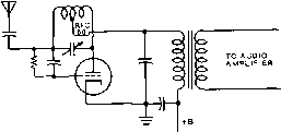 Figure 3 SUPERREGENERATIVE DETECTOR CIRCUIT A se/f-quenchecf superregenerofive detector such as illustrated above is capable of giving good sensitivity in the v-h-f range. However, the circuit has the disadvantage that its selectivity is relatively poor. Also, such a circuit should be preceded by an r-f stage to suppress the radiation of a signal by the ascillating detector. The optimum quenching frequency is a function of the signal frequency. As the operating frequency goes up, so does the optimum quenching frequency. When the quench frequency is too low, maximum sensitivity is not obtained. When it is too high, both sensitivity and selectivity suffer. In fact, the optimum quench frequency for an operating frequency below 15 Mc. is in the audible range. This makes the super-regenerator impracticable for use on the lower frequencies. The high background noise or hiss which is heard on a properly designed superregenerator when no signal is being received is not the quench frequency component; it is tube and tuned circuit fluctuation noise, indicating that the receiver is extremely sensitive. A moderately strong signal will cause the background noise to disappear completely, because the superregenerator has an inherent and instantaneous automatic volume control characteristic. This same a-v-c characteristic makes the receiver comparatively insensitive to impulse noise such as ignition pulses-a highly desirable feature. This characteristic also results in appreciable distortion of a received radiotelephone signal, but not enough to affect the intelligibility. The selectivity of a superregenerator is rather poor as compared to a superheterodyne, but is surprisingly good for so simple a receiver when figured on a percentage basis rather than absolute kc. bandwidth. FM Reception A superregenerative receiver will receive frequency modulated signals with results comparing favorably with amplitude modulation if the frequency swing of the FM transmitter is sufficiently high. For such reception, the receiver is detuned slightly to either side of resonance. ANT. О о I 4. i i0-i3omc I 03c. в 22 mc. rfc ,0025 022mc.-* output 100 к il2Ar7 I к JF-M Ihfc Wantenna audio output: R.F I AMPLIFIER I------1 IINTERMED. I MIXER f*-,FRe0UENCYl* amplifier i 1 I
LOCAL OSCILLATOP frequencyi lOSCILLATORI i (FOR c.w.) i Figure 5 ESSENTIAL UNITS OF A SUPERHETERODYNE RECEIVER The basic portions of the receiver are shown In solid blocks. Practicable receivers em-ploy the dotted blocks and also usually include such additional circuits as a noise limiter, an a-v-c circuit, and a crystal filter in the i-f amplifier. Figure 4 THE FREMODYNE SUPERREGENERATIVE SUPERHETERODYNE DETECTOR FOR FREQUENCY MODULATED SIGNALS Superregenerative receivers radiate a strong, broad, and rough signal. For this reason, it is necessary in most applications to employ a radio frequency amplifier stage ahead of the detector, with thorough shielding throughout the receiver. The Fremodyne The H a 2 e 11 i n e - Fremodyne Detector superregenerative circuit is expressly designed for reception of FM signals. This versatile circuit combines the action of the superregenerative receiver with the superhetrodyne, converting FM signals directly into audio signals in one double triode tube (figure 4). One section of the triode serves as a superregenerative mixer, producing an i-f of 22 Mc, an i-f amplifier, and a FM detector. The detector action is accomplished by slope detection tuning on the side of the if selectivity curve. This circuit greatly reduces the radiated signal, characteristic of the superregenerative detector, yet provides many of the desirable features of the superregeneraror. The pass-band of the Fremodyne detector is about 400 kc. 12-3 Superheterodyne Receivers Because of its superiority and nearly unir versal use in all fields of radio reception, the theory of operation of the superheterodyne should be familiar to every radio student and experimenter. The following discussion concerns superheterodynes for amplitude-modulation reception. It is, however, applicable in part to receivers for frequency modulation. Principle of In the superheterodyne, the in-Operation coming signal is applied to a mixer consisting of a non-linear impedance such as a vacuum tube or a diode. The signal is mixed with a steady signal generated locally in an oscillator stage, with the result that a signal bearing all the modulation applied to the original signal but of a frequency equal to the difference between the local oscillator and incoming signal frequencies appears in the mixer output circuit. The output from the mixer stage is fed into a fixed-tuned intermediate-frequency amplifier, where it is amplified and detected in the usual manner, and passed on to the audio amplifier. Figure 5 shows a block diagram of the fundamental superheterodyne arrangement. The basic components are shown in heavy lines, the simplest superheterodyne consisting simply of these three units. However, a good communications receiver will comprise all of the elements shown, both heavy and dotted blocks. Superheterodyne The advantages of super-Advantages heterodyne reception are directly attributable to the use of the fixed-tuned intermediate-frequency (i-f) amplifier. Since all signals are converted to the intermediate frequency, this section of the receiver may be designed for optimum selectivity and high amplification. High amplification is easily obtained in the intermediate-frequency amplifier, since it operates at a 1 ... 17 18 19 20 21 22 23 ... 80 |
|||||||||||||||||||||||||||||||||||||||||||||||||||||||||||||||||||||||||||||||||||||||||||||||||||||||||||||||||||||||||||||||||||||||||||||||||||||||||||||||||||||||||||||||||||||||||||||||||||||||||||||||||||||||||||||||||||||||||||||||||||||||||||||||||||||||||||||||||||
|
© 2026 AutoElektrix.ru
Частичное копирование материалов разрешено при условии активной ссылки |