 |
 |
 |
| Главная Журналы Популярное Audi - почему их так назвали? Как появилась марка Bmw? Откуда появился Lexus? Достижения и устремления Mercedes-Benz Первые модели Chevrolet Электромобиль Nissan Leaf |
Главная » Журналы » Simple coaxial reflectometer 1 ... 18 19 20 21 22 23 24 ... 80 HANDBOOK The Superhetrodyne 211 V*RIABLE-JU 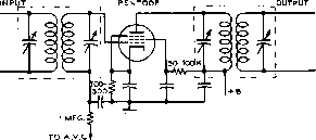 - BY-PASS CAPACITORS 05 TO 0.1 JUFD. Figure 6 TYPICAL IF AMPLIFIER STAGE relatively low frequency, where conventional pentode-type tubes give adequate voltage gain. A typical i-f amplifier is shown in figure 6. From the diagram it may be seen that both the grid and plate circuits are tuned. The tuned circuits used for coupling between i-f stages are known as i-f transformers. These will be more fully discussed later in this chapter. Choice of Inter- The choice of a frequency mediate Frequency for the i-f amplifier involves several considerations. One of these considerations concerns selectivity; the lower the intermediate frequency the greater the obtainable selectivity. On the other hand, a rather high intermediate frequency is desirable from the standpoint of image elimination, and also for the reception of signals from television and FM transmitters and modulated self-controlled oscillators, all of which occupy a rather wide band of frequencies, making a broad selectivity characteristic desirable. Images are a pecularity conunon to all superheterodyne receivers, and for this reason they are given a detailed discussion later in this chapter. While intermediate frequencies as low as 50 kc. are used where extreme selectivity is a requirement, and frequencies of 60 Mc. and above are used in some specialized forms of receivers, most present-day communications superheterodynes use intermediate frequencies around either 455 kc. or 1600 kc. Home-type broadcast receivers almost always use an i-f in the vicinity of 455 kc, while auto receivers usually use a frequency of about 262 kc. The standard frequency for the i-f channel of FM receivers is 10.7 Mc. Television receivers use an i-f which covers the band between about 21.5 and 27 Mc, although a new band between 41 and 46 Mc. is coming into more common usage. Arithmetical Aside from allowing the use of Selectivity fixed-tuned band-pass amplifier stages, the superheterodyne has an overwhelming advantage over the tuned radio frequency (t-r-f) type of receiver because of what is commonly known as arithmetical selectivity. This can best be illustrated by considering two receivers, one of the t-r-f type and one of the superheterodyne type, both attempting to receive a desired signal at 10,000 kc. and eliminate a strong interfering signal at 10,010 kc. In the t-r-f receiver, separating these two signals in the tuning circuits is practically impossible, since they differ in frequency by only 0.1 per cent. However, in a superheterodyne with an intermediate frequency of, for example, 1000 kc, the desired signal will be converted to a frequency of 1000 kc. and the interfering signal will be converted to a frequency of 1010 kc, both signals appearing at the input of the i-f amplifier. In this case, the two signals may be separated much more readily, since they differ by 1 per cent, or 10 times as much as in the first case. The Converter The converter stage, or mixer, Stage of a superheterodyne receiver can be either one of two types; (1) it may use a single envelope converter tube, such as a 6K8, 6SA7, or 6BE6, or (2) it may use two tubes, or two sets of elements in the same envelope, in an oscillator-mixer arrangement. Figure 7 shows a group of circuits of both types to illustrate present practice with regard to types of converter stages. Converter tube combinations such as shown in figures 7A and 7B are relatively simple and inexpensive, and they do an adequate job for most applications. With a converter tube such as the 6SB7-Y or the 6BA7 quite satisfactory performance may be obtained for the reception of relatively strong signals (as for example FM broadcast reception) up to frequencies in excess of 100 Mc. However, the equivalent input noise resistance of such tubes is of the order of 200,000 ohms, which is a rather high value indeed. So such tubes are not suited for operation without an r-f stage in the high-frequency range if weak-signal reception is desired. The 6L7 mixer circuit shown in figure 7C, and the 6BA7 circuit of figure 7D, also are characterized by an equivalent input noise resistance of several hundred thousand ohms, so that these also must be preceded by one or more r-f stages with a fairly high gain per stage if a low noise factor is desired of the complete receiver. However, the circuit arrangements shown at figures 7F and 6F are capable of low-noise operation within themselves, so that these circuits may be fed directly from the antenna without an r-f stage and still provide a good noise factor to the complete receiver. Note 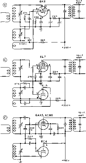 6SA7, 6SB7Y, 6BE6, 6BA7 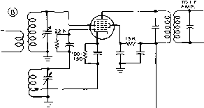 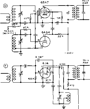 Figure 7 TYPICAL FREQUENCY-CONVERTER (MIXER) STAGES The relative advantages of the different circuits are discussed in the text that both these circuits use control-grid injection of both the incoming signal and the local-oscillator voltage. Hence, paradoxically, circuits such as these should be preceded by an r-f stage if local-oscillator radiation is to be held to any reasonable value of field intensity. Diode Mixers As the frequency of operation of a superheterodyne receiver is increased above a few hundred megacycles the signal-to-noise ratio appearing in the plate circuit of rhe mixer tube when triodes or pentodes are employed drops to a prohibitively low value. At frequencies above the upper-fre- quency limit for conventional mixer stages, mixers of the diode type are most commonly employed. The diode may be either a vacuum-tube heater diode of a special u-h-f design such as the 9005, or ir may be a crystal diode of the general type of the 1N21 through 1N28 series. 12-4 Mixer Noise and Images The effects of mixer noise and images are troubles common to all superheterodynes. Since HANDBOOK Mixer CPiaracteri sties 213 both these efiects can largely be obviated by the same remedy, they will be considered together. Mixer Noise Mixer noise of the shot-effect type, which is evidenced by a hiss in the audio output of the receiver, is caused by small irregularities in the plate current in the mixer stage and will mask weak signals. Noise of an identical nature is generated in an amplifier stage, but due to the fact that the conductance in the mixer stage is considerably lower than in an amplifier stage using the same tube, the proportion of inherent noise present in a mixer usually is considerably greater than in an amplifier stage using a comparable tube. Although this noise cannot be eliminated, its effects can be greatly minimized by placing sufficient signal-frequency amplification having a high signal-to-noise ratio ahead of the mixer. This remedy causes the signal output from the mixer to be large in proportion to the noise generated in the mixer stage. Increasing the gain after the mixer will be of no advantage in eliminating mixer noise difficulties; greater selectivity after the mixer will help to a certain extent, but cannot be carried too far, since this type of selectivity decreases the i-f band-pass and if carried too far will not pass the sidebands that are an essential part of a voice-modulated signal. Triode Mixers A triode having a high transconductance is the quietest mixer tube, exhibiting somewhat less gain but a better signal-to-noise ratio than a comparable multi-grid mixer tube. However, below 30 Mc. it is possible to construct a receiver that will get down to the atmospheric noise level without resorting to a triode mixer. The additional difficulties experienced in avoiding pulling, undesirable feedback, etc., when using a triode with control-grid injection tend to make multi-grid tubes the popular choice for this application on the lower frequencies. On very high frequencies, where set noise rather than atmospheric noise limits the weak signal response, triode mixers are more widely used. A 6]6 miniature twin triode with grids in push-pull and plates in parallel makes an excellent mixer up to about 600 Mc. Injection The amplitude of the injection volt-Voltoge age will affect the conversion transconductance of the mixer, and therefore should be made optimum if maximum signal-to-noise ratio is desired. If fixed bias is employed on the injection grid, the optimum injection voltage is quite critical. If cathode bias is used, the optimum voltage is not so critical; and if grid leak bias is employed, the optimum injection voltage is not at all critical just so it is adequate. Typical optimum injection voltages will run from 1 to 10 volts for control grid injection, and 45 volts or so for screen or suppressor grid injection. linages There always are two signal frequencies which will combine with a given frequency to produce the same difference frequency. For example: assume a superheterodyne with its oscillator operating on a higher frequency than the signal, which is common practice in present superheterodynes, tuned to receive a signal at 14,100 kc. Assuming an i-f amplifier frequency of 450 kc, the mixer input circuit will be tuned to 14,100 kc, and the oscillator to 14,100 plus 450, or 14,550 kc. Now, a strong signal at the oscillator frequency plus the intermediate frequency (14,550 plus 450, or 15,000 kc.) will also give a difference frequency of 450 kc in the mixer output and will be heard also. Note that the image is always twice the intermediate frequency away from the desired signal. Images cause repeat points on the tuning dial. The only way that the image could be eliminated in this particular case would be to make the selectivity of the mixer input circuit, and any circuits preceding it, great enough so that the l5,000-kc. signal never reaches the mixer grid in sufficient amplitude to produce interference. For any particular intermediate frequency, image interference troubles become increasingly greater as the frequency to which the signal-frequency portion of the receiver is tuned is increased. This is due to the fact that the percentage difference between the desired frequency and the image frequency decreases as the receiver is tuned to a higher frequency. The ratio of strength between a signal at the image frequency and a signal at the frequency to which the receiver is tuned producing equal output is known as the image ratio. The higher this ratio, the better the receiver in regard to image-interference troubles. With but a single tuned circuit between the mixer grid and the antenna, and with 400-500 kc. i-f amplifiers, image ratios of 60 db and over are easily obtainable up to frequencies around 2000 kc. Above this frequency, greater selectivity in the mixer grid circuit through the use of additional tuned circuits between the mixer and the antenna is necessary if a good image ratio is to be maintained. 12-5 R-F Stages Since the necessary tuned circuits between the mixer and the antenna can be combined with tubes to form r-f amplifier stages, the PENTODE -чк> f INPUT <3<,0  О -Wr- O OUTPUT Figure 8 TYPICAL PENTODE R-F AMPLIFIER STAGE reduction of the effects of mixer noise and the increasing of the image ratio can be accomplished in a single section of the receiver. When incorporated in the receiver, this section is known simply as an r-f amplifier; when it is a separate unit with a separate tuning control it is often known as a preselector. Either one or two stages are commonly used in the preselector or r-f amplifier. Some preselectors use regeneration to obtain still greater amplification and selectivity. An r-f amplifier or preselector embodying more than two stages rarely ever is employed since two stages will ordinarily give adequate gain to Override mixer noise. R-F Stages in Generally speaking, atmos-the V-H-F Range pheric noise in the frequency range above 30 Mc. is quite low-so low, in fact, that the noise generated within the receiver itself is greater than the noise received on the antenna. Hence it is of the greatest importance that internally generated noise be held to a minimum in a receiver. Ar frequencies much above 300 Mc. there is not too much that can be done ar the present state of the art in the direction of reducing receiver noise below that generated in the converter stage. But in the v-h-f range, between 30 and 300 Mc, the receiver noise factor in a well designed unit is determined by the characteristics of the first r-f stage. The usual v-h-f receiver, whether for communications or for FM or TV reception, uses a miniature pentode for the first r-f amplifier stage. The 6AK5 is the best of presently available types, with the 6CB6 and the 6DC6 closely approaching the 6AK5 in performance. But when gain in the first r-f stage is not so important, and the best noise factor must be obtained, the first r-f stage usually uses a triode. Shown in figure 9 are four commonly used types of triode r-f stages for use in the v-h-f range. The circuit at (A) uses few components and gives a moderate amount of gain with very low noise. It is most satisfactory when the first r-f stage is to be fed directly from a low- ® GROUNDED-GRID 6AB4, 6J6, eJ4, -12AT7 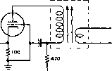 ® CATHODE-COUPLED 6J6 © LOW NOISE CASCODE 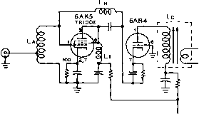 ® 6BK7. 6BCi7AOR 6BZ7j 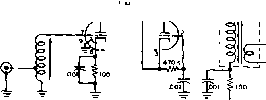 Figure 9 TYPICAL TRIODE V-H-F R-F AMPLIFIER STAGES Triode r-f stages contribute the least amount of noise output for a given signal level, hence their frequent use in the v-h-f range. impedance coaxial transmission line. Figure 9 (B) gives somewhat more gain than (A), but requires an input matching circuit. The effective gain of this circuit is somewhat reduced when it is being used to amplify a broad band of frequencies since the effective of the cathode-coupled dual tube is somewhat less HANDBOOK The Cascode Amplifier 215 ® CRYSTAL OSCILLATOR
VARIABLE OSCILLATOR VARIABLE OSCILLATOR
FIXED OSCILLATOR CONVENTIONAL COMMUNICATIONS RECEIVER I HIGHLY SELECTIVE ACCESSORY I.F. l AMPLIFIER AND DEMODULATOR (QSER JI Figure 10 TYPICAL DOUBLE-CONVERSION SUPERHETERODYNE RECEIVERS /ffusfrofec/ at (A) is the basic circuit of a commercial double-conversion superhelerodYne receiver. Af (B) is illustrated the application of an accessor/ sharp i-f channel for obtaining improved se/ectiVify from о convent/опо/ communications receiver through the use of the c/oubfe-conversion principle. than half the of either of the two tubes taken alone. The Cascode The Cascode r-f amplifier, de-Amplifier veloped at the MIT Radiation Laboratory during World War II, is a low noise circuit employing a grounded cathode triode driving a grounded grid triode, as shown in figure 9C. The stage gain of such a circuit is about equal to that of a pentode tube, while the noise figure remains at the low level of a triode tube. Neutralization of the first triode tube is usually unnecessary below 50 Mc. Above this frequency, a definite improvement in the noise figure may be obtained through the use of neutralization. The neutralizing coil, Ln, should resonate at the operating frequency with the grid-plate capacity of the first triode tube. The 6BQ7A and 6BZ7 tubes are designed for use in cascode circuits, and may be used to good advantage in the 144 Mc. and 220 Mc, amateur bands (figure 9D). For operation at higher frequencies, the 6Aj4 tube is recommended. Double Conversion As previously mentioned, the use of a higher intermediate frequency will also improve the image ratio, at the expense of i-f selectivity, by placing the desired signal and the image farther apart. To give both good image ratio at the higher frequencies and good selectivity in the i-f amplifier, a system known as double conversion is sometimes employed. In this system, the incoming signal is first converted to a rather high intermediate frequency, and then amplified and again converted, this time to a much lower frequency. The first intermediate frequency supplies the necessary wide separation between the image and the desired signal, while the second one supplies the bulk of the i-f selectivity. The double-conversion system, as illustrated in figure 10, is receiving two general types of application at the present time. The first application is for the purpose of attaining extremely good stability in a communications receiver through the use of crystal control of the first oscillator. In such an arrangement, as used in several types of Collins receivers, the first oscillator is crystal controlled and is followed by a tunable i-f amplifier which then is followed by a mixer stage and a fixed-tuned i-f amplifier on a much lower frequency. Through such a circuit arrangement the star bility of the complete receiver is equal to the stability of the oscillator which feeds the second mixer, while the selectivity is determined by the bandwidth of the second, fixed i-f amplifier. The second common application of the double-conversion principle is for the purpose of obtaining a very high degree of selectivity in the complete communications receiver. In this type of application, as illustrated in figure 10 (B), a conventional communications receiver is modified in such a manner that its normal i-f amplifier (which usually is in the 450 to 915 kc. range) instead of being fed to a demodulator and then to the audio system, is alternatively fed to a fixed-tune mixer stage and then into a much lower intermediate frequency amplifier before the signal is demodulated and fed to the audio system. The accessory i-f amplifier system (sometimes called a Q5er) normally is operated on a frequency of 175 kc, 85 kc, or 50 kc. 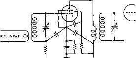 TOA.V.C. - Figure 11 ILLUSTRATING COMMON POINT BY.PASSING To rerfoce the detrimental effects of cathode circuit inductance in v-h-f stages, all by-pass capacitors sfmuld be returned to the cathode terminal at the sDcfeet. Tubes with two cathode leads can give improved performance if the grid return is made to one cathode terminal while the plate and screen by-pass returns are made to the cathode terminal which is connected to the suppressor within the tube. 12-6 Signol-Frequency Tuned Circuits The signal-frequency tuned circuits in high-frequency superheterodynes and tuned radio frequency types of receivers consist of coils of either the solenoid or universal-wound types shunted by variable capacitors. It is in these tuned circuits that the causes of success or failure of a receiver often lie. The universal-wound type coils usually are used at frequencies below 2000 kc; above this frequency the single-layer solenoid type of coil is more satisfactory. Impedance The two factors of greatest signi-and Q ficance in determining the gain- per-stage and selectivity, respectively, of a tuned amplifier are tuned-circuit impedance and tuned-circuit Q. Since the resistance of modern capacitors is low at ordinary frequencies, the resistance usually can be considered to be concentrated in the coil. The resistance to be considered in making Q determinations is the r-f resistance, not the d-c resistance of the wire in the coil. The latter ordinarily is low enough that it may be neglected. The increase in r-f resistance over d-c resistance primarily is due to skin effect and is influenced by such factors as wire size and type, and the proximity of metallic objects or poor insulators, such as coil forms with high losses. Higher values of Q lead to better selectivity and increased r-f voltage across the tuned circuit. The increase in voltage is due to an increase in the circuit impedance with the higher values of q. Frequenrly it is possible to secure an increase in impedance in a resonant circuit, and consequently an increase in gain from an amplifier stage, by increasing the reactance through the use of larger coils and smaller tuning capacitors (higher L/C ratio). Input Resistonce Another factor which influences the operation of tuned circuits is the input resistance of the tubes placed across these circuits. At broadcast frequencies, the input resistance of most conventional r-f amplifier tubes is high enough so that it is not bothersome. But as the frequency is increased, the input resistance becomes lower and lower, until it ultimately reaches a value so low that no amplification can be obtained from the r-f stage. The two contributing factors to the decrease in input resistance with increasing frequency are the transit time required by an electron traveling between the cathode and grid, and the inductance of the cathode lead common to both the plate and grid circuits. As the frequency becomes higher, rhe transit time can become an appreciable portion of the time required by an r-f cycle of the signal voltage, and current will actually flow into the grid. The result of this effect is similar ro that which would be obtained by placing a resistance between the tubes grid and cathode. Superheterodyne Because the oscillator in a Trocking superheterodyne operates offset from the other front end circuits, it is necessary to make special provisions to allow the oscillator to track when similar tuning capacitor sections are HANDBOOK Tuning Circuits 217 PAODIMG CAPACITOR TUNING CAPACITOR 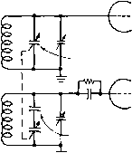 MIXER OSCILLATOR SERIES TRACKING CAPACITOR О О о о о ® о о о Тср Тсв
Figure 12 SERIES TRACKING EMPLOYED IN THE H-F OSCILLATOR OF A SUPERHETERODYNE Tfi series tracking capacitor permits fhe use of identical gangs in a ganged capacitor, since fhe tracking capacitor slows down the rate of frequency change in the oscillatof so that a constant dif-ference in frequency between the oscillator and the r-f stage (equal to the i-f amplifier frequency) may be maintained. ganged. The usual method of obtaining good tracking is to operate the oscillator on the high-frequency side of the mixer and use a series tracking capacitor to slow down the tuning rate of the oscillator. The oscillator tuning rate must be slower because it covers a smaller range than does the mixer when both are expressed as a percentage of frequency. At frequencies above 7000 kc. and with ordinary intermediate frequencies, the difference in percentage between the two tuning ranges is so small that it may be disregarded in receivers designed to cover only a small range, such as an amateur band. A mixer and oscillator tuning arrangement in which a series tracking capacitor is provided is shown in figure 12. The value of the tracking capacitor varies considerably with different intermediate frequencies and tuning ranges, capacitances as low as .0001 fifd. being used at the lower tuning-range frequencies, and values up to .01 fifd. being used at the higher frequencies. Superheterodyne receivers designed to cover only a single frequency range, such as the standard broadcast band, sometimes obtain tracking between the oscillator and the r-f circuits by cutting the variable plates of the oscillator tuning section to a different shape from those used to tune the r-f stages. Frequency Range The frequency to which a Selection receiver responds may be varied by changing the size of either the coils or the capacitors in the tuning circuits, or both. In short-wave receivers Figure 13 BANDSPREAD CIRCUITS Parallel bandspread is illustrated at (A) and (B), series bandspread at (Q, and tapped-coil band-spread at (D), a combination of both methods is usually employed, the coils being changed from one band to another, and variable capacitors being used to tune the receiver across each band. In practical receivers, coils may be changed by one of two methods: a switch, controllable from the panel, may be used to switch coils of different sizes into the tuning circuits or, alternatively, coils of different sizes may be plugged manually into the receiver, the connection into the tuning circuits being made by suitable plugs on the coils. Where there are several plug-in coils for each band, they are sometimes arranged to a single mounting strip, allowing them Jill to be plugged in simultaneously. Bandspread In receivers using large tuning Tuning capacit s to cover the short- wave spectrum with a minimum of coils, tuning is likely to be quite difficult, owing to the large frequency range covered by a small rotation of the variable capacitors. To alleviate this condition, some method of slowing down the tuning rate, or bandspread-ing, must be used. Quantitatively, bandspread is usually designated as being inversely proportional to the range covered. Thus, a large amount of band-spread indicates that a small frequency range is covered by the bandspread control. Conversely, a small amount of bandspread is taken to mean that a Zflrge frequency range is covered by the bandspread dial. Types of Bandspreading systems are of Bandspread two general types: electrical and mechanical. Mechanical systems are exemplified by high-ratio dials in which the tuning capacitors rotate much more slowly than the dial knob. In this system, there is often a separate scale or pointer either connected or geared to the dial knob to facilitate accurate dial readings. However, there is a practical limit to the amount of mechanical bandspread which can be obtained in a dial and capacitor before the speed-reduction unit and capacitor bearings become prohibitively expensive. Hence, most receivers employ a combination of electrical and mechanical band-spread. In such a system, a moderate reduction in the tuning rate is obtained in the dial, and the rest of the reduction obtained by electrical bandspreading. Stroy Circuit In this book and in other radio Capacitance literature, mention is sometimes made of stray or circuit capacitance. This capacitance is in the usual sense defined as the capacitance remaining across a coil when all the tuning, bandspread, and padding capacitors across the circuit are at their minimum capacitance setting. Circuit capacitance can be attributed to two general sources. One source is that due to the input and ouфut capacitance of the tube when its cathode is heated. The input capacitance varies somewhat from the static value when the tube is in actual operation. Such factors as plate load impedance, grid bias, and frequency will cause a change in input capacitance. However, in all except the extremely high-transconductance tubes, the published measured input capacitance is reasonably close to the effective value when the tube is used within its recommended frequency range. But in the high-transconductance types the effective capacitance will vary considerably from the published figures as operating conditions are changed. The second source of circuit capacitance, and that which is more easily controllable, is that contributed by the minimum capacitance of the variable capacitors across the circuit and that due to capacitance between the wiring and ground. In well-designed high-frequency receivers, every effort is made to keep this portion of the circuit capacitance at a minimum since a large capacitance reduces the tuning range available with a given coil and prevents a good L/C ratio, and consequently a high-impedance tuned circuit, from being obtained. A good percentage of stray circuit capacitance is due also to distributed capacitance of the coil and capacitance between wiring points and chassis. Typical values of circuit capacitance may run from 10 to 75 fiySA. in high-frequency receivers, the first figure representing concentric-line receivers with acorn or miniature tubes and extremely small tuning capacitors. and the latter representing all-wave sets with bandswitching, large tuning capacitors, and conventional tubes. 12-7 I-F Tuned Circuits I-f amplifiers usually employ bandpass circuits of some sort. Л bandpass circuit is exactly what the name implies-a circuit for passing a band of frequencies. Bandpass arrangements can be designed for almost any degree of selectivity, the type used in any particular case depending upon the ultimate application of the amplifier. I-P Intermediate frequency trans- Transformers formers ordinarily consist of two or more tuned circuits and some method of coupling the tuned circuits together. Some representative arrangements are shown in figure 14. The circuit shown at A is the conventional i-f transformer, with the coupling, M, between the tuned circuits being provided by inductive coupling from one coil to the other. As the coupling is increased, the selectivity curve becomes less peaked, and when a condition known as critical coupling is reached, the top of the curve begins to flatten out. When the coupling is increased still more, a dip occurs in the top of the curve. The windings for this type of i-f transformer, as well as most others, nearly always consist of small, flat universal-wound pies mounted either on a piece of dowel to provide an air core or on powdered-iron for iron core i-f transformers. The iron-core transformers generally have somewhat more gain and better selectivity than equivalent air-core units. The circuits shown at figure 14-В and С are quite similar. Their only difference is the type of mutual coupling used, an inductance being used at В and a capacitance at C. The operation of both circuits is similar. Three resonant circuits are formed by the components. In B, for example, one resonant circuit is formed by Ll, Cl, Cj and L all in series. The frequency of this resonant circuit is just the same as that of a single one of the coils and capacitors, since the coils and capacitors are similar in both sides of the circuit, and the resonant frequency of the two capacitors and the two coils all in series is the same as that of a single coil and capacitor. The second resonant frequency of the complete circuit is determined by the characteristics of each half of the circuit containing the mutual coupling device. In B, this second frequency will be lower than the first, since the resonant frequency of Ll, Cl and the inductance, M, or Lj, C and M is lower than that of a single coil and capaci- HANDBOOK I-F Amplifiers 219 tor, due to the inductance of M being added to the circuit. The opposite effect takes place at figure 14-C, where the common coupling impedance is a capacitor. Thus, at С the second resonant frequency is higher than the first. In either case, however, the circuit has two resonant frequencies, resulting in a flat-topped selectivity curve. The width of the top of the curve is controlled by the reactance of the mutual coupling component. As this reactance is increased (inductance made greater, capacitance made smaller), the two resonant frequencies become further apart and the curve is broadened. In the circuit of figure 14-D, there is inductive coupling between the center coil and each of the outer coils. The result of this arrangement is that the center coil acts as a sharply tuned coupler between the other two. A signal somewhat off the resonant frequency of the transformer will not induce as much current in the center coil as will a signal of the correct frequency. When a smaller current is induced in the center coil, it in turn transfers a still smaller current to the output coil. The effective coupling between the outer coils increases as the resonant frequency is approached, and remains nearly constant over a small range and then decreases again as the resonant band is passed. Another very satisfactory bandpass arrangement, which gives a very straight-sided, flat-topped curve, is the negative-mutual arrangement shown at figure 14-E. Energy is transferred between the input and output circuits in this arrangement by both the negative-mutual coils, M, and the common capacitive reactance, C. The negative-mutual coils are interwound on the same form, and connected backward. Transformers usually are made tunable over a small range to permit accurate alignment in the circuit in which they are employed. This is accomplished either by means of a variable capacitor across a fixed inductance, or by means of a fixed capacitor across a variable inductance. The former usually employ either a mica-compression capacitor (designated mica tuned ), or a small air dielectric variable capacitor (designated air tuned ). Those which use a fixed capacitor usually employ a powdered iron core on a threaded rod to vary the inductance, and are known as permeability tuned. Shape Factor It is obvious that to pass modulation sidebands and to allow for slight drifting of the transmitter carrier frequency and the receiver local oscillator, the i-{ amplifier must pass not a single frequency but a band of frequencies. The width of this pass band, usually 5 to 8 kc. at maximum о о о о о о о о о о о о о о о о о о о о Ji тг о Ci % Сг О О о о о о о © о о о о о о о т -к т о о о о о о о о о о C1 С2 © о о о о о о о 7Г о о о о о 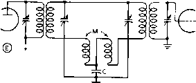 Figure 14 I-F AMPLIFIER COUPLING ARRANGEMENTS 7Ъе wterstage coupling arrangements illustrated above give a better shape factor (more straight sided selectivity curve) than would the same number of tuned circuits coupled by means of tubes. width in a good communications receiver, is known as the pass batid, and is arbitrarily taken as the width between the two frequencies at which the response is attenuated 6 db, or is 6 db down. However, it is apparent that to discriminate against an interfering signal which is stronger than the desired signal, much more than 6 db attenuation is required. The attenuation arbitrarily taken to indicate adequate discrimination against an interfering signal is 60 db. 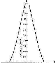 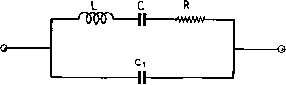 -15 -10 -5 4Ь5 +5 +10 +15 Figure 16 ELECTRICAL EQUIVALENT OF QUARTZ FILTER CRYSTAL The crystal is equivalent to a very large value of inductance in series with small values of capacitance and resistance, with a larger though still small value af capacitance across the who/e circuit (representing holder capacitance plus stray capacitances). Figure 15 IF PASS BAND OF TYPICAL COMMUNICATIONS RECEIVER It is apparent that it is desirable to have the bandwidth at 60 db down as narrow as possible, bur it must be done without making the pass band (6 db points) too narrow for satisfactory reception of the desired signal. The figure of merit used to show the ratio of bandwidth at 6 db down to that at 60 db down is designated shape factor. The ideal i-f curve, a rectangle, would have a shape factor of 1.0. The i-f shape factor in typical communications receivers runs from 3.0 to 5.5. The most practicable method of obtaining a low shape factor for a given number of tuned circuits is to employ them in pairs, as in figure 14-A, adjusted to critical coupling (the value at which two resonance points just begin to become apparent). If this gives too sharp a nose or pass band, then coils of lower Q should be employed, with the coupling maintained at the critical value. As the Q is lowered, closer coupling will be required for crirical coupling. Conversely if the pass band is too broad, coils of higher Q should be employed, the coupling being maintained at critical. If the pass band is made more narrow by using looser coupling instead of raising the Q and main-taninig critical coupling, the shape factor will not be as good. The pass hand will not be much narrower for several pairs of identical, critically coupled tuned circuits than for a single pair. However, the shape factor will be greatly improved as each additional pair is added, up to about 5 pairs, beyond which the improvement for each additional pair is not significant. Commer-cially available communications receivers of good quality normally employ 3 or 4 double tuned transformers with coupling adjusted to critical or slightly less. The pass band of a typical communication receiver having a 455 kc. i-f amplifier is shown in figure 15. Miller As mentioned previously, the dyna-Effect mic input capacitance of a tube varies slightly with bias. As a-v-c voltage normally is applied to i-f tubes for radiotele-phony reception, the effective grid-cathode capacitance varies as rhe signal strength varies, which produces the same effect as slight detuning of the i-f transformer. This effect is known as Miller effect, and can be minimized to the extent that it is not troublesome either by using a fairly low L/C ratio in the transformers or by incoфorating a small amount of degenerative feedback, the latter being most easily accomplished by leaving part of the cathode resistor unbypassed for r.f. Crystal Filters The pass band of an intermediate frequency amplifier may be made very narrow through the use of a piezoelectric filter crystal employed as a series resonant circuit in a bridge arrangement known as a crystal filter. The shape factor is quite poor, as would be expected when the selectivity is obtained from the equivalent of a single tuned circuit, but the very narrow pass band obtainable as a result of the extremely high Q of the crystal makes the crystal filter useful for c-w telegraphy reception. The pass band of a 455 kc. crystal filter may be made as narrow as 50 cycles, while the narrowest pass band that c£in be obtained with a 455 kc. tuned circuit of practicable dimensions is about 5 kc. The electrical equivalent of a filter crystal is shown in figure 16. For a given frequency, L is very high, С very low, and R (assuming 1 ... 18 19 20 21 22 23 24 ... 80 |
||||||||||||||||||||||||||||||||||||||||||||||||||||||||||||||||||||||||||||||||||||||
|
© 2026 AutoElektrix.ru
Частичное копирование материалов разрешено при условии активной ссылки |