 |
 |
 |
| Главная Журналы Популярное Audi - почему их так назвали? Как появилась марка Bmw? Откуда появился Lexus? Достижения и устремления Mercedes-Benz Первые модели Chevrolet Электромобиль Nissan Leaf |
Главная » Журналы » Simple coaxial reflectometer 1 ... 19 20 21 22 23 24 25 ... 80 HANDBOOK Crystal Filters 221  E OUT Figure 17 EQUIVALENT OF CRYSTAL FILTER CIRCUIT For a given voltags out of the generator, the voltage developed across Zj depends upon the ratio of the impedance ofXto the sum af the impedances af Z on J Zl. Because of the high Q of the crystal, Its impedance changes rapidly with changes in frequency. a good crystal of high Q) is very low. Capacitance Cl represents the shunt capacitance of the electrodes, plus the crystal holder and wiring, and is many times the capacitance of C. This makes the crystal act as a parallel resonant circuit with a frequency only slightly higher than that of its frequency of series resonance. For crystal filter use it is the series resonant characteristic that we are primarily interested in. The electrical equivalent of the basic crystal filter circuit is shown in figure 17. If the impedance of Z plus is low compared to the impedance of the crystal X at resonance, then the current flowing through Zj, and the voltage developed across it, will be almost in inverse proportion to the impedance of X, which has a very sharp resonance curve. If the impedance of Z plus is made high compared to the resonant impedance of X, then there will be no appreciable drop in voltage across Zl as the frequency departs from the resonant frequency of X until the point is reached where the impedance of X approaches that of Z plus Zl. This has the effect of broadening out the curve of frequency versus voltage developed across Zi, which is another way of saying that the selectivity of the crystal filter (but not the crystal proper) has been reduced. In practicable filter circuits the impedances Z and Zl usually are represented by some form of tuned circuit, but the basic principle of operation is the same. Practical Filters It is necessary to balance out the capacitance across the crystal holder (Ci, in figure 16) to prevent bypassing around the crystal undesired signals off the crystal resonant frequency. The balancing is done by a phasing circuit which takes out-of-phase voltage from a balanced in- о о о о о SELECTIVITY CONTROL PHASING CONTROL Figure 18 TYPICAL CRYSTAL FILTER CIRCUIT put circuit and passes it to the output side of the crystal in proper phase to neutralize that passed through the holder capacitance. A representative practical filter arrangement is shown in figure 18. The balanced input circuit may be obtained either through the use of a split-stator capacitor as shown, or by the use of a center-tapped input coil. Variable-Selec- In the circuit of figure 18, the tivity Filters selectivity is minimum with the crystal input circuit tuned to resonance, since at resonance the impedance of the tuned circuit is maximum. As the input circuit is detuned from resonance, however, the impedance decreases, and the selectivity becomes greater. In this circuit, the output from the crystal filter is tapped down on the i-f stage grid winding to provide a low value of series impedance in the output circuit. It will be recalled that for maximum selectivity, the total impedance in series with the crystal (both input and ouфut circuits) must be low. If one is made low and the other is made variable, then the selectivity may be varied at will from sharp to broad. The circuit shown in figure 19 also achieves variable selectivity by adding a variable impedance in series with the crystal circuit. In this case, the variable impedance is in series with the crystal output circuit. The impedance of the ouфut circuit is varied by varying the Q. As the Q is reduced (by adding resistance in series with the coil), the impedance decreases and the selectivity becomes greater. The input circuit impedance is made low by using a non-resonant secondary on the input transformer. A variation of the circuit shown at figure 19 consists of placing the variable resistance across the coil and capacitor, rather than in series with them. The result of adding the resistor is a reduction of the ouфut impedance, and an increase in selectivity. The circuit behaves oppositely to that of figure 19, however; as the resistance is lowered the selectivity becomes greater. Still another variation of figure 19 is to use the tuning capacitor across the ouфut coil to vary the ouфut impedance. CRYSTAL о о о о о о о о Г ь PHASIKIC CONTROL О о о о SELECTIVITY CONTROL Figure 19 VARIABLE SELECTIVITY CRYSTAL FILTER This circuit permits of a greater aorrtrol of selectivity than does the circuit of figure 16, and does not require a split-stator variable capacitor. CRYSTAL NOTCH 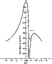 As the output circuit is detuned from resonance, its impedance is lowered, and the selectivity increases. Sometimes a set of fixed capacitors and a multipoint switch are used to give step-by-step variation of the output circuit tuning, and thus of the crystal filter selectivity. Rejection As previously discussed, a filter Notch crystal has both a resonant(seties resonant) and an anti-resonant (parallel resonant) frequency, the impedance of the crystal being quite low at the former frequency, and quite high at the latter frequency. The anti-resonant frequency is just slightly higher than the resonant frequency, the difference depending upon the effective shunt capacitance of the filter crystal and holder. As adjustment of the phasing capacitor controls the effective shunt capacitance of the crystal, it is possible to vary the anti-resonant frequency of the crystal slightly without unbalancing the circuit sufficiently to let undesired signals leak through the shunt capacitance in appreciable amplitude. At the exact anti-resonant frequency of the crystal the attenuation is exceedingly high, because of the high impedance of the crystal at this frequency. This is called the rejection notch, and can be utilized virtually to eliminate the heterodyne image or repeat tuning of c-w signals. The beat frequency oscillator can be so adjusted and the phasing capacitor so adjusted that the desired beat note is of such a pitch that the image (the same audio note on the other side of Zero beat) falls in the rejection notch and is inaudible. The receiver then is said to be adjusted for single-signal operation. The rejection notch sometimes can be employed to reduce interference from an undesired phone signal which is very close in frequency to a desired phone signal. The filter is adjusted to broad so as to permit tele- Figure 20 I-F PASS BAND OF TYPICAL CRYSTAL FILTER COMMUNICATIONS RECEIVER phony reception, and the receiver tuned so that the carrier frequency of the undesired signal falls in the rejection notch. The modulation sidebands of the undesired signal still will come through, but the carrier heterodyne will be effectively eliminated and interference greatly reduced. A typical crystal selectivity curve for a communications receiver is shown in figure 20. Crystal Filter A crystal filter, especially Considerations when adjusted for single signal reception, greatly reduces interference and background noise, the latter feature permitting signals to be copied that would ordinarily be too weak to be heard above the background hiss. However, when the filter is adjusted for maximum selectivity, the pass band is so narrow that the received signal must have a high order of stability in order to stay within the pass band. Likewise, the local oscillator in the receiver must be highly stable, or constant retuning will be required. Another effect that will be noticed with the filter adjusted too sharp is a tendency for code characters to produce a ringing sound, and have a hangover or tails. This effect limits the code speed that can be copied satisfactorily when the filter is adjusted for extreme selectivity. The Mechanical The Collins Mechanical Fil-Filter ter (figure 21) is a new con- cept in the field of selectivity. It is an electro-mechanical bandpass filter about half the size of a cigarette package. As shown in figure 22, it consists of an input transducer, a resonant mechanical sec- HANDBOOK Collins Mechanical Filter 223 tion comprised of a number of metal discs, and an output transducer. The frequency characteristics of the resonant mechanical section provide the almost rectangular selectivity curves shown in figure 23. The input and ouфut transducers serve Only as electrical to mechanical coupling devices and do not affect the selectivity characteristics which are determined by the metal discs. An electrical signal applied to the input terminals is converted into a mechanical vibration at the input transducer by means of magnetostriction. This mechanical vibration travels through the resonant mechanical section to the ouфut transducer, where it is converted by magnetostriction to an electrical signal which appears at the ouфut terminals. In order to provide the most efficient electromechanical coupling, a small magnet in the mounting above each transducer applies a magnetic bias to the nickel transducer core. The electrical impulses then add to or subtract from this magnetic bias, causing vibration of the filter elements that corresponds to the exciting signal. There is no mechanical motion except for the imperceptible vibration of the metal discs. Magnetostrictively-driven mechanical filters have several advantages over electrical equivalents. In the region from 100 kc. to 500 kc, the mechanical elements are extremely small, and a mechanical filter having better selectivity than the best of conventional i-f systems may be enclosed in a package smaller than one i-f transformer. Since mechanical elements with Qs of 5000 or more are readily obtainable, mechanical filters may be designed in accordance with the theory for lossless elements. This permits filter characteristics that are unobtainable with electrical circuits because of the relatively high losses in electrical elements as compared with the mechanical elements used in the filters. one supporting disc at each END COUPLINS RODS bias magnet 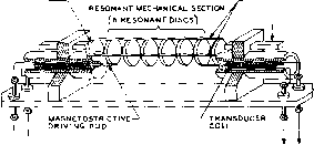 ♦ ♦ electrical signal (input or output) electrical signal (INPUT OrOUTPUtI 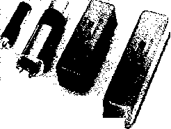 Figure 21 COLLINS MECHANICAL FILTERS Tbe Collins Mechanical Filter is an electro-mechanical bandpass filter which surpasses, in one small unit, the selectivity of conventional, space-consuming filters. At the left is tne miniaturized filter, less than lk long. Type H is next, and two horizontal mounting types are at right. For exploded view of Collins Mechanical Filter, see figure 46. The frequency characteristics of the mechanical filter are permanent, and no adjustment is required or is possible. The filter is enclosed in a hermetically sealed case. In order to realize full benefit from the mechanical filters selectivity characteristics, it is necessary to provide shielding between the external input and ouфut circuits, capable of reducing transfer of energy external to the 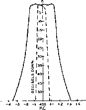 Figure 22 MECHANICAL FILTER FUNCTIONAL DIAGRAM Figure 23 Se/ectivity curves af 45S-kc mecbenicej ftlfers with nominal 0.8-l(C. (dotted line) and 3.7-kc. (solid line) bandwidth at -6 db. г I о о I So I 0001 6SJ7 10 к POT. LVERV SMALL /Г (1-2JUiJF.) ГТО 2N0 I DETECTOR I.F. STAGE  DtT. j-F AUDIO ® GRID LEAK DETECTOR Figure 24 VARfABLE-OUTPUT B-F-0 ClRCUfT A beor-freguenc) ascillator whose output is con-trollablo is of considerable assistance in cop/fng c-w signals over a wide range of levels, and such a control is almost a necessity for satisfactory copying of slngle-sideband radiophone signals. filter by a minimum value of 100 db. If the input circuit is allowed to couple energy into the output circuit external to the filter, the excellent skirt selectivity will deteriorate and the passband characteristics will be distorted. As with almost any mechanically resonant circuit, elements of the mechanical filter have multiple resonances. These result in spurious modes of transmission through the filter and produce minor passbands at frequencies on other sides of the primary passband. Design of the filter reduces these sub-bands to a low level and removes them from the immediate area of the major passband. Two conventional i-f transformers supply increased attenuation to these spurious responses, and are sufficient to reduce them to an insignificant level. Beat-Frequency The beat-frequency oscillator. Oscillators usually called the b.f.o., is a necessary adjunct for reception of c-w telegraph signals on superheterodynes which have no other provision for obtaining modulation of an incoming c-w telegraphy signal. The oscillator is coupled into or just ahead of second detector circuit and supplies a signal of nearly the same frequency as that of the desired signal from the i-f amplifier. If the i-f amplifier is tuned to 455 kc, for example, the b.f.o. is tuned to approximately 454 or 456 kc. to produce an audible (1000 cycle) beat note in the output of the second detector of the receiver. The carrier signal itself is, of course, inaudible. The b.f.o. is not used for voice reception, except as an aid in searching for weak stations. The b-f-o input to the second detector need only be sufficient to give a good beat note on an average signal. Too much coupling into the second detector will give an excessively high hiss level, masking weak signals by the high noise background. Figure 24 shows a method of manually ad- -AUDIO (B) DIODE DETECTOR
© PLATE DETECTOR I-F. STAGE 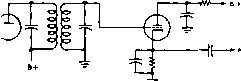 (Б) INFINITE IMPEDANCE DETECTOR Figure 25 TYPICAL CIRCUITS FOR GRID-LEAK, DIODE, PLATE AND INFINITE IMPEDANCE DETECTOR STAGES justing the b-f-o output to correspond with the strength of received signals. This type of variable b-f-o output control is a useful adjunct to any superheterodyne, since it allows sufficient b-f-o output to be obtained to beat with strong signals or to allow single-sideband reception and at the same time permits the b-f-o оифи1, and consequently the hiss, to be reduced when attempting to receive weak signals. The circuit shown is somewhat better than those in which one of the electrode volt- HANDBOOK Detector Circuits 225 DET., A.V.C. 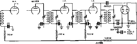 Figure 26 TYPICAL A-V-C CIRCUIT USING A DOUBLE DIODE Any of the small dual-dlode tubes may be used In this circuit. Or, if desired, a duo-diode-triode may be used, with the triode acting as the first audio stage. The left-hmd diode serves as the iktector, while the right-hand side acts as the a-vc rectifier. The use of separate diodes for detector and a-v-c reduces distortion when receiving an AM signal viith a high modulation percentage. ages on the b-f-o tube is changed, as the latter circuits usually change the frequency of the b.f.o. at the same time they change the strength, making it necessary to reset the trimmer each time the ouфut is adjusted. The b.f.o. usually is provided with a small trimmer which is adjustable from the front panel to permit adjustment over a range of 5 or 10 kc. For single-signal reception the b.f.o. always is adjusted to the high-frequency side, in order to permit placing the heterodyne image in the rejection notch. In order to reduce the b-f-o signal output voltage to a reasonable level which will prevent blocking the second detector, the signal voltage is delivered through a low-capacitance (high-reactance) capacitor having a value of 1 to 2 iifitd. Care must be taken with the b.f.o. to prevent harmonics of the oscillator from being picked up at multiples of the b-f-o frequency. The complete b.f.o. together with the coupling circuits to the second detector, should be thoroughly shielded to prevent pickup of the harmonics by the input end of the receiver. If b-f-o harmonics still have a tendency to give trouble after complete shielding and isolation of the b-f-o circuit has been accomplished, the passage of these harmonics from the b-f-o circuit to the rest of the receiver can be stopped through the use of a low-pass filter in the lead between the output of the b-f-o circuit and the point on the receiver where the b-f-o signal is to be injected. 12-8 Detector, Audio, and Control Circuits Detectors Second detectors for use in superheterodynes are usually of the diode, plate, or infinite-impedance types. Occasionally, grid-leak detectors are used in receivers using one i-f stage or none at all, in which case the second detector usually is made regenerative. Diodes are the most popular second detectors because they allow a simple method of obtaining automatic volume control to be used. Diodes load the tuned circuit to which they are connected, however, and thus reduce the selectivity slightly. Special i-f transformers are used for the purpose of providing a low-impedance input circuit to the diode detector. Typical circuits for grid-leak, diode, plate and infinite-impedance detectors are shown in figure 25. Automatic Vol- The elements of an automatic ume Control volume control (a.v.c.) sys- tem are shown in figure 26. A dual-diode tube is used as a combination diode detector and a-v-c rectifier. The left-hand diode operates as a simple rectifier in the manner described earlier in this chapter. Audio voltage, superimposed on a d-c voltage, appears across the 500,000-ohm potentiometer (the volume control) and the .0001-fifd. capacitor, and is passed on to the audio amplifier. The right-hand diode receives signal voltage directly from the primary of the last i-f amplifier, and acts as the a-v-c rectifier. The pulsating d-c voltage across the 1-megohm a.v.c-diode load resistor is filtered by a 500,000-ohm resistor and a .05-ftfd. capacitor, and applied as bias to the grids of the r-f and i-f amplifier tubes; an increase or decrease in signal strength will cause a corresponding increase or decrease in a-v-c bias voltage, and thus the gain of the receiver is automatically adjusted to compensate for changes in signal strength. A-C Loading o{ By disassociating tlie a.v.c. Second Detector and detecting functions through using separate diodes, as shown, most of the ill effects of et-c shunt loading on the detector diode are avoided. This type of loading causes serious distortion, and the additional components required to eliminate it are well worth their cost. Even with the circuit shown, a-c loading can occur unless a very high (5 megohms, or more) value of grid resistor is used in the following audio amplifier stage. A.V.C. in In receivers having a beat- B-F-G-Equipped frequency oscillator for the Receivers reception of radiorelegraph signals, the use of a.v.c. can result in a great loss in sensitivity when the b.f.o. is switched on. This is because the beat oscillator output acts exacrly like a strong received signal, and causes the a-v-c circuit to put high bias on the r-f andi-f stages, thus greatly reducing the receivers sensitivity. Due to the above effect, it is necessary to provide a method of making the a-v-c circuit inoperative when the b.f.o. is being used. The simplest method of eliminating the a-v-c action is to shorr the a-v-c line to ground when the b.f.o. is turned on. A two-circuit switch may be used for the dual purpose of turning on the beat oscillator and shorting out the a.v.c. if desired. Signal Strength Visual means for determining Indicators whether or not the receiver is properly tuned, as well as an indication of the relative signal strength, are both provided by means of tuning indicators (S meters) of the meter or vacuum-tube type. A d-c milliammeter can be connected in the plate supply circuit of one or more r-f or i-f amplifiers, as shown in figure 27A, so that the change in plate current, due to the action of the a-v-c voltage, will be indicated on the instrument. The d-c instrument MA should have a full-scale reading approximately equal to the total plate current taken by the stage or stages whose plate current passes through the instrument. The value of this current can be estimated by assuming a plate current on each stage (with no signal input to the receiver) of about 6 ma. However, it will be found to be more satisfactory ro measure rhe actual plate current on the stages with a milliammeter of perhaps 0-100 ma. full scale before purchasing an instrument for use as an S meter. The 50-ohm potentiometer shown in the drawing is used to adjust the meter reading to full scale with no signal input to the receiver. When an ordinary meter is used in the plate circuit of a srage, for the purpose of indicating signal strength, the meter reads backwards 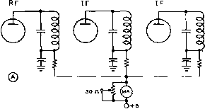 RFOHIF ®  1 SRk -t- i о о 7 о о RFORIF © 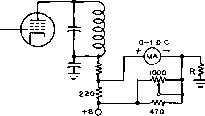 6U5/6G5 1МЕв. OR 6Е5 -WV-  о +2bOV Figure 27 SIGNAL-STRENGTH-METER CIRCUITS Shown above ore four circuits for obtaining a sig-nal-strength reading Vfhich is a function of incoming carrier amplitude. The circuits are discussed I in the accompanying text. with respect to strength. This is because increased a-v-c bias on stronger signals causes lower plate current through the meter. For this reason, special meters which indicate zero at the right-hand end of the scale are often used for signal strength indicators in commercial receivers using this type of circuit. Alternatively, the meter may be mounted upside down, so that the needle moves toward the right with increased strength. The circuit of figure 27B can frequently be used to advantage in a receiver where the cathode of one of the r-f or i-f amplifier srages runs directly to ground through the cathode bias resistor instead of running through a cath- HANDBOOK Noise Suppression 227 ode-voltage gain control. In this case a 0-1 d-c milliammeter in conjunction with a resistor from 1000 to 3000 ohms can be used as shown as a signal-strength meter. With this circuit the meter will read backwards with increasing signal strength as in the circuit previously discussed. Figure 27C is the circuit of a forward-reading S meter as is often used in communications receivers. The instrument is used in an unbalanced bridge circuit with the d-c plate resistance of one i-f tube as one leg of the bridge and with resistors for the other three legs. The value of the resistor R must be determined by trial and error and will be somewhere in the vicinity of 50,000 ohms. Sometimes the screen circuits of the r-f and i-f stages are taken from this point along with the screen-circuit voltage divider. Electron-ray tubes (sometimes called magic eyes ) can also be used as indicators of relative signal strength in a circuit similar to that shown in figure 27D, A 6U5/6G5 tube should be used where the a-v-c voltage will be from 5 to 20 volts and a type 6E5 tube should be used when the a-v-c voltage will run from 2 to 8 volts. Audio Amplifiers Audio amplifiers are employed in nearly all radio receivers. The audio amplifier stage or stages are usually of the Class A type, although Class AB push-pull stages are used in some receivers. The purpose of the audio amplifier is to bring the relatively weak signal from the detector up to a strength sufficient to operate a pair of headphones or a loud speaker. Either triodes, pentodes, or beam tetrodes may be used, the pentodes and beam tetrodes usually giving greater output. In some receivers, particularly those employing grid leak detection, it is possible to operate the headphones directly from the detector, without audio amplification. In such receivers, a single audio stage with a beam tetrode or pentode tube is ordinarily used to drive the loud speaker. Most communications receivers, either home-constructed or factory-made, have a single-ended beam tetrode (such as a 6L6 or 6V6) or pentode (6F6 or бКб-GT) in the audio output stage feeding the loudspeaker. If precautions are not taken such a stage will actually bring about a decrease in rhe effective signal-to-noise ratio of the receiver due ro the rising high-frequency characteristic of such a stage when feeding a loud-speaker. One way of improving this condition is to place a mica or paper capacitor of approximately 0.003 ftfd. capacitance across the primary of the output transformer. The use of a capacitor in this manner tends to make the load impedance seen by the plate of the output tube more constant over the audio-frequency range. The speaker spd transformer will tend to present a rising impedance to the tube as the frequency increases, and the parallel capacitor will tend to make the total impedance more constant since it will tend to present a decreasing impedance with increasing audio frequency. A still better way of improving the frequency characteristic of the ouфut stage, and at the same time reducing the harmonic distortion, is to use shunt feedback from the plate of the оифиГ tube to the plate of a tube such as a 6SJ7 acting as an audio amplifier stage ahead of the оифиг stage. 12-9 Noise Suppression The problem of noise suppression confronts the listener who is located in places where interference from power lines, electrical appliances, and automobile ignition systems is troublesome. This noise is often of such intensity as to swamp out signals from desired stations. There are two principal methods for reducing this noise: (1) A-c Hne filters at the source of interference, if the noise is created by an electrical appliance. (2) Noise-limiting circuits for the reduction, in the receiver itself, of interference of the type caused by automobile ignition systems. Power Line Many household appliances, such Filters as electric mixers, heating pads, vacuum sweepers, refrigerators, oil burners, sewing machines, doorbells, etc, create an interference of an intermittent nature. The insertion of a line filter near the source of interference often will effect a complete cure. Filters for small appliances can consist of a 0.1-ntd. capacitor connected a-cross the 110-volt a-c line. Two capacitors in series across the line, with the midpoint connected to ground, can be used in conjunction with ultraviolet ray machines, refrigerators, oil burner furnaces, and other more stubborn offenders. In severe cases of interference, additional filters in the form of heavy-duty r-f choke coils must be connected in series with the 110-volt a-c line on both sides of the line right at the interfering appliance. Peak Noise Numerous noise-limiting circuits Limiters which are beneficial in overcom- ing key clicks, automobile ignition interference, and similar noise impulses have become popular. They operate on the principle that each individual noise pulse is of very short duration, yet of very high amplitude. The popping or clicking type of noise from electrical ignition systems may produce a signal having a peak value ten ro twenty times as great as the incoming radio signal, but an average power much less than the signal. As the duration of this type of noise peak is short, the receiver can be made inoperative during the noise pulse without the human ear detecting the total loss of signal. Some noise limiters actually punch a hole in the signal, while others merely limit the maximum peak signal which reaches rhe headphones or loudspeaker. The noise peak is of such short duration that it would not be objectionable except for the fact that it produces an over-loading effect on the receiver, which increases its time constant. A sharp voltage peak will give a kick to the diaphragm of the headphones or speaker, and the momentum or inertia keeps the diaphragm in motion until the dampening of the diaphragm stops it. This movement produces a popping sound which may completely obliterate the desired signal. If the noise pulse can be limited to a peak amplitude equal to thar of the desired signal, the resulting interference is practically negligible for moder-arely low repetition rates, such as ignition noise. In addition, the i-f amplifier of the receiver will also tend to lengthen the duration of the noise pulses because the relatively high-Q i-f tuned circuits will ring or oscillate when excited by a sharp pulse, such as produced by ignirion noise. The most effective noise limiter woiild be placed before the high-Q i-f tuned circuits. At this point the noise pulse is the sharpest and has not been degraded by passage through the i-f transformers. In addition, the pulse is eliminated before it can produce ringing effects in the i-f chain. The Lamb An i-f noise limiter is shown in Noise Limiter figure 28. This is an adaptation of the Lamb noise silencer circuit. The i-f signal is fed into a double grid tube, such as a 6L7, and thence into the i-f chain. A 6AB7 high gain pentode is capacity coupled to the input of the i-f system. This auxiliary tube amplifies both signal and noise that is fed to it. It has a minimum of selectivity ahead of it so that it receives the true noise pulse before it is degraded by the i-f strip. A broadly tuned i-f transformer is used to couple the noise amplifier to a 6Нб noise rectifier. The gain of the noise amplifier is controlled by a potentiometer in the cathode of the 6AB7 noise amplifier. This potentiometer controls the gain of the noise amplifier I5T DEI. 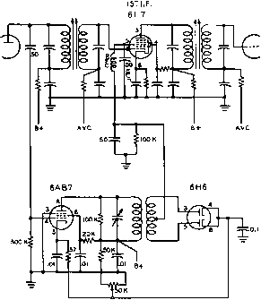 Figure 28 THE LAMB I-F NOISE SILENCER stage and in addition sets the bias level on the бНб diode so that the incoming signal will not be rectified. Only noise peaks louder than the signal can overcome the resting bias of the 6H6 and cause it to conduct. A noise pulse rectified by the 6Н6 is applied as a negative voltage to the control grid of the 6L7 i-f tube, disabling the tube, and punching a hole in the signal at the instant of the noise pulse. By varying the bias control of the noise limiter, the negative control voltage applied to the 6L7 may be adjusted until it is barely suffi-cienr to overcome the noise impulses applied to the #1 control grid without allowing the modulation peaks of the carrier to become badly distorred. The Bishop Another effective i-f noise Noise Limiter limiter is the Bishop limiter. This is a full-wave shunt type diode limiter applied to the primary of the last i-f transformer of a receiver. The limiter is self-biased and automatically adjusts itself to the degree of modulation of the received signal. The schematic of this limiter is shown in figure 29. The bias circuir time constant is determined by Ci and the shunt resistance, which consists of and Rj in series. The plate resistance of the last i-f tube and the capacity of Cj determine the charging rate of the circuit. The limiter is disabled by opening Si, which allows the bias to rise to the value of the i-f signal. HANDBOOK Noise Limiters 22 9 СП\,001 о о о о о о 1 т Figure 29 THE BISHOP I-F NOISE LIMITER Audio Noise Some of the simplest and most Limiters practical peak limiters for radio- telephone reception employ one or two diodes either as shunt or series limiters in the audio system of the receiver. When a noise pulse exceeds a certain predetermined threshold value, the limiter diode acts either as a short or open circuit, depending upon whether it is used in a shunt or series circuit. The threshold is made to occur at a level high enough that it will not clip modulation peaks enough to impair voice intelligibility, but low enough to limit the noise peaks effectively. Because the action of the peak limiter is needed most on very weak signals, and these usually are not strong enough to produce proper a-v-c action, a threshold setting that is correct for a strong phone signal is not correct for optimum limiting on very weak signals. For this reason the threshold control often is tied in with the a-v-c system so as to make the optimum threshold adjustment automatic instead of manual. Suppression of impulse noise by means of an audio peak limiter is best accomplished at the very front end of the audio system, and for this reason the function of superheterodyne second detector and limiter often are combined in a composite circuit. The amount of limiting that can be obtained is a function of the audio distortion that can be tolerated. Because excessive distortion will reduce the intelligibility as much as will background noise, the degree of limiting for which the circuit is designed has to be a compromise. Peak noise limiters working at the second detector are much more effective when the i-f bandwidth of the receiver is broad, because a sharp i-f amplifier will lengthen the pulses by the time they reach the second detector, making the limiter less effective. V-h-f superheterodynes have an i-f bandwidth considerably wider than the minimum necessary for voice sidebands (to take care of drift and instability). Therefore, they are capable of bet- ter peak noise suppression than a standard communications receiver having an i-f bandwidth of perhaps 8 kc. Likewise, when a crystal filter is used on the sharp position an a-f peak limiter is of little benefit. Practical Noise limiters range all the Peak Noise way from an audio stage Limiter Circuits running at very low screen or plate voltage, to elaborate affairs employing 5 or more tubes. Rather than attempt to show the numerous types, many of which are quite complex considering the results obtained, only two very similar types will be described. Either is just about as effective as the most elaborate limiter that can be constructed, yet requires the addition of but a single diode and a few resistors and capacitors over what would be employed in a good superheterodyne without a limiter. Both circuits, with but minor modifications in resistance and capacitance values, are incorporated in one form or another in different types of factory-built communications receivers. Referring to figure 30, the first circuit shows a conventional superheterodyne second detector, a.v.c, and first audio stage with the addition of one tube element, Dj, which may be either a separate diode or part of a twin-diode as illustrated. Diode Dj acts as a series gate, allowing audio to get to the grid of the a-f tube only so long as the diode is conducting. The diode is biased by a d-c voltage obtained in the same manner as a-v-c control voltage, the bias being such that pulses of short duration no longer conduct when the pulse voltage exceeds the carrier by approximately 60 per cent. This also clips voice modulation peaks, but not enough to impair intelligibility. It is apparent that the series diode clips only positive modulation peaks, by limiting upward modulation to about 60 per cent. Negative or downward peaks are limited automatically to 100 per cent in the detector, because obviously the rectified voltage out of the diode detector cannot be less than zero. Limiting the downward peaks to 60 per cent or so instead of 100 per cent would result in but little improvement in noise reduction, and the results do not justify the additional components required. It is important that the exact resistance values shown be used, for best results, and that 10 per cent tolerance resistors be used for R3 and R . Also, the rectified carrier voltage developed across Cj should be at least 5 volts for good limiting. The limiter will work weii on c-w telegraphy if the amplitude of beat frequency oscillator injection is not too high. Variable injection is to be preferred, adjustable from the front panel. LAST IF, TUBE 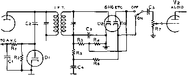 Q-O.I./lfd. paper Cj 50-MAifd. mica Сз-lOO-flMfd. mica C4, Cs-O.Ol-Mfd. paper Rii 12- megohm, Yi watt Rj, -220,000 ohms, Yi watt R5, Re-1 megohm, Уг watt Rj-2-megahm potentiometer Figure 30 NOISE LIMITER CIRCUIT, WITH ASSOCIATED A-V-C This limiter is of the series type, and is self-adjustitig io carrier strength for phone reception. For proper operatiorj several volts should be developed across the secondary of the last i-f transformer (IFT) under carrier conditions. If this feature is not provided, the b-f-o injection should be reduced to the lowest value that will give a satisfactory beat. When this is done, effective limiting and a good beat can be obtained by proper adjustment of the r-f and a-f gain controls. It is assumed, of course, that the a.v.c. is cut out of the circuit for c-w telegraphy reception. Alternative The circuit of figure 31 is Limiter Circuit more effective than that shown in figure 30 under certain conditions and requires the addition of only one more resistor and one more capacitor than the other circuit. Also, this circuit involves a smaller loss in output level than the circuit of figure 30. This circuit can be used with equal effectiveness with a combined diode-triode or diode-pentode tube (6R7, 6SR7, 6Q7, 6SQ7 or similar diode-triodes, or 6B8, 6SF7, or similar diode-pentodes) as diode detector and first audio stage. However, a separate diode must be used for the noise limiter, D. This diode may be one-half of a бНб, 6AL5, 7A6, ere, or it may be a triode connected 6j5, 6C4 or similar type. Note that the return for the volume control must be made to the cathode of the detector diode (and not to ground) when a dual tube is used as combined second-detector first-audio. This means that in the circuit shown in figure 31 a connection will exist across the points where the X is shown on the diagram since a common cathode lead is brought out of the tube for Dl and Vi- If desired, of course, a single dual diode may be used for Di and Dj in this circuit as well as io the circuit of figure 30. Switching the limiter in and out with the switch S brings abour no change in volume. In any diode limiter circuit such as the ones shown in these two figures it is important that the mid-point of the heater potential for the noise-limiter diode be as close to ground potential as possible. This means that the center-tap of the heater supply for the tubes should be grounded wherever possible rather than grounding one side of the heater supply as is often done. Difficulry with hum pickup in the limiter circuit may be encountered when one side of the heater is grounded due to the high values of resistance necessary in the limiter circuit. The circuit of figure 31 has been used with excellent success in several home-constructed receivers, and in the BC-312/BC-342 and ВС-348 series of surplus communications receivers. It is also used in certain manufactured receivers. An excellent check on the operation of the noise limiter in any communications receiver can be obtained by listening to the Loran signals in the l60-meter band. With the limiter out a sharp rasping buzz will be obtained when one of these stations is tuned in. With the noise limiter switched into the circuit the buzz should be greatly reduced and a low-pitched hum should be heard. The Full-Wave The most satisafctory diode Limiter noise limiter is the series full- wave limiter, shown in figure 32. The positive noise peaks are clipped by diode A, the clipping level of which may be adjusted to clip at any modulation level between 25 per cent and 100 per cent. The nega-ative noise peaks are clipped by diode В at a fixed level. The TNS Limiter The Twin Noise Squelch, popularized by CQ magazine, is a combination of a diode noise clipper and an audio squelch tube. The squelch cir- 1 ... 19 20 21 22 23 24 25 ... 80 |
|
© 2026 AutoElektrix.ru
Частичное копирование материалов разрешено при условии активной ссылки |